Connect ESP32 to Cloud MQTT Broker (TTGO T-Call ESP32 SIM800L)
This guide shows how to connect the TTGO T-Call ESP32 SIM800L board to the Internet using a SIM card data plan and publish/subscribe to a cloud MQTT broker without using Wi-Fi. The cloud MQTT Mosquitto broker will be installed on a Digital Ocean server. We'll also use Node-RED to visualize the readings and control the outputs from anywhere. The board will be programmed using Arduino IDE.
![]() With this setup, you can monitor and control your ESP32 from anywhere in the world, and the ESP32 doesn't need to be connected to a wireless router because it connects to the internet using a SIM card data plan.
With this setup, you can monitor and control your ESP32 from anywhere in the world, and the ESP32 doesn't need to be connected to a wireless router because it connects to the internet using a SIM card data plan.
Introducing the TTGO T-Call ESP32 SIM800L
The TTGO T-Call is an ESP32 development board that combines a SIM800L GSM/GPRS module. You can get if for approximately $11.
![]() Besides Wi-Fi and Bluetooth, you can communicate with this ESP32 board using SMS or phone calls and you can connect it to the internet using your SIM card data plan. This is great for IoT projects that don't have access to a nearby router.
Important: the SIM800L works on 2G networks, so it will only work in your country, if 2G networks are available. Check if you have 2G network in your country, otherwise it won't work.
To use the capabilities of this board you need to have a nano SIM card with data plan and a USB-C cable to upload code to the board.
Besides Wi-Fi and Bluetooth, you can communicate with this ESP32 board using SMS or phone calls and you can connect it to the internet using your SIM card data plan. This is great for IoT projects that don't have access to a nearby router.
Important: the SIM800L works on 2G networks, so it will only work in your country, if 2G networks are available. Check if you have 2G network in your country, otherwise it won't work.
To use the capabilities of this board you need to have a nano SIM card with data plan and a USB-C cable to upload code to the board.
![]() The package includes some header pins, a battery connector, and an external antenna that you should connect to your board.
The package includes some header pins, a battery connector, and an external antenna that you should connect to your board.
![]() However, we had some issues with that antenna, so we decided to switch to another type of antenna and all the problems were solved. The following figure shows the new antenna.
However, we had some issues with that antenna, so we decided to switch to another type of antenna and all the problems were solved. The following figure shows the new antenna.
![]()
Project Overview
The idea of this project is to connect your ESP32 to a Cloud MQTT broker to subscribe to an MQTT topic and publish sensor data to MQTT topics. The ESP32 doesn't need to have access to a router via Wi-Fi, because it connects to the internet using a SIM card data plan.
![]() In a previous project, we created our own server with a database to plot sensor readings in charts that you can access from anywhere in the world.
In this project, we'll publish sensor readings to a server via MQTT and we'll use Mosquitto broker. You can publish your sensor readings to any other cloud broker.
In summary, here's how the project works:
In a previous project, we created our own server with a database to plot sensor readings in charts that you can access from anywhere in the world.
In this project, we'll publish sensor readings to a server via MQTT and we'll use Mosquitto broker. You can publish your sensor readings to any other cloud broker.
In summary, here's how the project works:
The T-Call ESP32 SIM800L board is connected to the internet using a SIM card data plan.
The T-Call ESP32 SIM800L board publishes the sensor readings via MQTT and the readings are displayed in Node-RED Dashboard.
Through Node-RED Dashboard, you can press buttons to send on and off commands to control the ESP32 GPIOs.
We'll be using a BME280 sensor, but you can use any other sensor that best suits your needs.
Cloud MQTT Broker
You can search for a free cloud MQTT broker, however we'll be using our own cloud MQTT broker. We recommend using Digital Ocean with MQTT Mosquitto Broker, because it can handle all the project requirements. We'll also use Node-RED software to visualize the readings in gauges and publish MQTT messages to the ESP32.
Run Your Cloud MQTT Mosquitto Broker (access from anywhere using Digital Ocean)
Access Node-RED Dashboard from Anywhere (using Digital Ocean)
Prerequisites
1. ESP32 add-on Arduino IDE
We'll program the ESP32 using Arduino IDE. So, you need to have the ESP32 add-on installed in your Arduino IDE. Follow the next tutorial, if you haven't already.
Installing the ESP32 Board in Arduino IDE (Windows, Mac OS X, Linux)
2. Preparing your Cloud MQTT Broker
In this project we'll show you how to exchange data via MQTT using a cloud MQTT broker.
We'll be using our own cloud MQTT broker. However, if you find a free MQTT broker with all your desired features it will also work
If you want to follow this exact project, you should follow the next two tutorials to prepare your own server and Node-RED software.
Run Your Cloud MQTT Mosquitto Broker (access from anywhere using Digital Ocean)
Access Node-RED Dashboard from Anywhere (using Digital Ocean)
The ESP32 is publishing temperature readings every 30 seconds on the esp/temperature and esp/humidity topics. It's subscribed to these two topics esp/output1 and esp/output2 to update the state of the output LEDs.
Having Node-RED running, go to your server IP address followed by :1880.
http://cloud-mqtt-broker-ip-address:1880
Wire your nodes as shown below:
![]() Finally, deploy your flow (press the button on the upper right corner).
Finally, deploy your flow (press the button on the upper right corner).
![]() Alternatively, you can go to Menu > Import and copy the following to your Clipboard to create your Node-RED flow.
[{"id":"a2c394d8.1544e8","type":"mqtt in","z":"537cca59.c4a014","name":"","topic":"esp/temperature","qos":"2","datatype":"auto","broker":"18f874c0.4a464b","x":140,"y":1020,"wires":[["6907217e.f39bf"]]},{"id":"b83c2ecf.8ab94","type":"mqtt in","z":"537cca59.c4a014","name":"","topic":"esp/humidity","qos":"2","datatype":"auto","broker":"18f874c0.4a464b","x":130,"y":1100,"wires":[["c92e354e.a27d48"]]},{"id":"ee844c66.3eda2","type":"mqtt out","z":"537cca59.c4a014","name":"","topic":"esp/output1","qos":"1","retain":"","broker":"18f874c0.4a464b","x":330,"y":1180,"wires":[]},{"id":"54540fba.e5877","type":"mqtt out","z":"537cca59.c4a014","name":"","topic":"esp/output2","qos":"1","retain":"","broker":"18f874c0.4a464b","x":330,"y":1260,"wires":[]},{"id":"56080a9a.c7bba4","type":"ui_switch","z":"537cca59.c4a014","name":"","label":"Output 1","tooltip":"","group":"1539f836.ed9378","order":0,"width":0,"height":0,"passthru":true,"decouple":"false","topic":"","style":"","onvalue":"true","onvalueType":"bool","onicon":"","oncolor":"","offvalue":"false","offvalueType":"bool","officon":"","offcolor":"","x":120,"y":1180,"wires":[["ee844c66.3eda2"]]},{"id":"417bd6d1.1d1468","type":"ui_switch","z":"537cca59.c4a014","name":"","label":"Output 2","tooltip":"","group":"1539f836.ed9378","order":0,"width":0,"height":0,"passthru":true,"decouple":"false","topic":"","style":"","onvalue":"true","onvalueType":"bool","onicon":"","oncolor":"","offvalue":"false","offvalueType":"bool","officon":"","offcolor":"","x":120,"y":1260,"wires":[["54540fba.e5877"]]},{"id":"6907217e.f39bf","type":"ui_gauge","z":"537cca59.c4a014","name":"","group":"1539f836.ed9378","order":2,"width":0,"height":0,"gtype":"gage","title":"Temperature","label":"Celsius Degrees","format":"{{value}}","min":"-10","max":"40","colors":["#00b500","#e6e600","#ca3838"],"seg1":"","seg2":"","x":350,"y":1020,"wires":[]},{"id":"c92e354e.a27d48","type":"ui_gauge","z":"537cca59.c4a014","name":"","group":"1539f836.ed9378","order":2,"width":0,"height":0,"gtype":"gage","title":"Humidity","label":"%","format":"{{value}}","min":"0","max":"100","colors":["#93dae6","#0074cc","#002561"],"seg1":"","seg2":"","x":340,"y":1100,"wires":[]},{"id":"18f874c0.4a464b","type":"mqtt-broker","z":"","name":"","broker":"localhost","port":"1883","clientid":"","usetls":false,"compatmode":false,"keepalive":"60","cleansession":true,"birthTopic":"","birthQos":"0","birthPayload":"","closeTopic":"","closeQos":"0","closePayload":"","willTopic":"","willQos":"0","willPayload":""},{"id":"1539f836.ed9378","type":"ui_group","z":"","name":"Dashboard","tab":"38becbd0.c13714","order":1,"disp":true,"width":"6","collapse":false},{"id":"38becbd0.c13714","type":"ui_tab","z":"","name":"Home","icon":"dashboard","disabled":false,"hidden":false}]
View raw code
Alternatively, you can go to Menu > Import and copy the following to your Clipboard to create your Node-RED flow.
[{"id":"a2c394d8.1544e8","type":"mqtt in","z":"537cca59.c4a014","name":"","topic":"esp/temperature","qos":"2","datatype":"auto","broker":"18f874c0.4a464b","x":140,"y":1020,"wires":[["6907217e.f39bf"]]},{"id":"b83c2ecf.8ab94","type":"mqtt in","z":"537cca59.c4a014","name":"","topic":"esp/humidity","qos":"2","datatype":"auto","broker":"18f874c0.4a464b","x":130,"y":1100,"wires":[["c92e354e.a27d48"]]},{"id":"ee844c66.3eda2","type":"mqtt out","z":"537cca59.c4a014","name":"","topic":"esp/output1","qos":"1","retain":"","broker":"18f874c0.4a464b","x":330,"y":1180,"wires":[]},{"id":"54540fba.e5877","type":"mqtt out","z":"537cca59.c4a014","name":"","topic":"esp/output2","qos":"1","retain":"","broker":"18f874c0.4a464b","x":330,"y":1260,"wires":[]},{"id":"56080a9a.c7bba4","type":"ui_switch","z":"537cca59.c4a014","name":"","label":"Output 1","tooltip":"","group":"1539f836.ed9378","order":0,"width":0,"height":0,"passthru":true,"decouple":"false","topic":"","style":"","onvalue":"true","onvalueType":"bool","onicon":"","oncolor":"","offvalue":"false","offvalueType":"bool","officon":"","offcolor":"","x":120,"y":1180,"wires":[["ee844c66.3eda2"]]},{"id":"417bd6d1.1d1468","type":"ui_switch","z":"537cca59.c4a014","name":"","label":"Output 2","tooltip":"","group":"1539f836.ed9378","order":0,"width":0,"height":0,"passthru":true,"decouple":"false","topic":"","style":"","onvalue":"true","onvalueType":"bool","onicon":"","oncolor":"","offvalue":"false","offvalueType":"bool","officon":"","offcolor":"","x":120,"y":1260,"wires":[["54540fba.e5877"]]},{"id":"6907217e.f39bf","type":"ui_gauge","z":"537cca59.c4a014","name":"","group":"1539f836.ed9378","order":2,"width":0,"height":0,"gtype":"gage","title":"Temperature","label":"Celsius Degrees","format":"{{value}}","min":"-10","max":"40","colors":["#00b500","#e6e600","#ca3838"],"seg1":"","seg2":"","x":350,"y":1020,"wires":[]},{"id":"c92e354e.a27d48","type":"ui_gauge","z":"537cca59.c4a014","name":"","group":"1539f836.ed9378","order":2,"width":0,"height":0,"gtype":"gage","title":"Humidity","label":"%","format":"{{value}}","min":"0","max":"100","colors":["#93dae6","#0074cc","#002561"],"seg1":"","seg2":"","x":340,"y":1100,"wires":[]},{"id":"18f874c0.4a464b","type":"mqtt-broker","z":"","name":"","broker":"localhost","port":"1883","clientid":"","usetls":false,"compatmode":false,"keepalive":"60","cleansession":true,"birthTopic":"","birthQos":"0","birthPayload":"","closeTopic":"","closeQos":"0","closePayload":"","willTopic":"","willQos":"0","willPayload":""},{"id":"1539f836.ed9378","type":"ui_group","z":"","name":"Dashboard","tab":"38becbd0.c13714","order":1,"disp":true,"width":"6","collapse":false},{"id":"38becbd0.c13714","type":"ui_tab","z":"","name":"Home","icon":"dashboard","disabled":false,"hidden":false}]
View raw code
3. SIM Card with data plan
To use the TTGO T-Call ESP32 SIM800L board, you need a nano SIM card with a data plan. We recommend using a SIM card with a prepaid or monthly plan, so that you know exactly how much you'll spend.
4. APN Details
To connect your SIM card to the internet, you need to have your phone plan provider APN details. You need the domain name, username and password.
In my case, I'm using vodafone Portugal. If you search for GPRS APN settings followed by your phone plan provider name, (in my case its: GPRS APN vodafone Portugal), you can usually find in a forum or in their website all the information that you need.
I've found this website that can be very useful to find all the information you need.
It might be a bit tricky to find the details if you don't use a well known provider. So, you might need to contact your provider directly.
5. Libraries
You need to install these libraries in your Arduino IDE to proceed with this project: Adafruit_BME280, Adafruit_Sensor, TinyGSM, and PubSubClient. Follow the next instructions to install these libraries.
Installing the Adafruit BME280 Library
Open your Arduino IDE and go to Sketch > Include Library > Manage Libraries. The Library Manager should open.
Search for adafruit bme280 on the Search box and install the library.
![]()
Installing the Adafruit Sensor Library
To use the BME280 library, you also need to install the Adafruit_Sensor library. Follow the next steps to install the library in your Arduino IDE:
Go to Sketch > Include Library > Manage Libraries and type Adafruit Unified Sensor in the search box. Scroll all the way down to find the library and install it.
![]()
Installing the TinyGSM Library
In the Arduino IDE Library Manager search for TinyGSM. Select the TinyGSM library by Volodymyr Shymanskyy.
![]()
Installing the PubSubClient Library
Search for PubSubClient and scroll down. Select the PubSubClient library by Nick O'Leary.
![]() After installing the libraries, restart your Arduino IDE.
After installing the libraries, restart your Arduino IDE.
Parts Required
To build this project, you need the following parts:
TTGO T-Call ESP32 SIM800L
USB-C cable
Antenna (optional)
BME280 sensor module (Guide for BME280 with ESP32)
2x LEDs
2x 220 ohm resistors
Breadboard
Jumper wires
You can use the preceding links or go directly to MakerAdvisor.com/tools to find all the parts for your projects at the best price!
![]()
Schematic Diagram
Wire the BME280 sensor and two LEDs to the T-Call ESP32 SIM800L board as shown in the following schematic diagram.
![]() We're connecting the BME280's SDA pin to GPIO 18 and the SCL pin to GPIO 19.
We're connecting the BME280's SDA pin to GPIO 18 and the SCL pin to GPIO 19.
Code
Copy the following code to your Arduino IDE but don't upload it yet. First, you need to make some modifications to make it work.
/*
Rui Santos
Complete project details at https://RandomNerdTutorials.com/esp32-cloud-mqtt-broker-sim800l/
Permission is hereby granted, free of charge, to any person obtaining a copy
of this software and associated documentation files.
The above copyright notice and this permission notice shall be included in all
copies or substantial portions of the Software.
*/
// Select your modem:
#define TINY_GSM_MODEM_SIM800 // Modem is SIM800L
// Set serial for debug console (to the Serial Monitor, default speed 115200)
#define SerialMon Serial
// Set serial for AT commands
#define SerialAT Serial1
// Define the serial console for debug prints, if needed
#define TINY_GSM_DEBUG SerialMon
// set GSM PIN, if any
#define GSM_PIN ""
// Your GPRS credentials, if any
const char apn[] = ""; // APN (example: internet.vodafone.pt) use https://wiki.apnchanger.org
const char gprsUser[] = "";
const char gprsPass[] = "";
// SIM card PIN (leave empty, if not defined)
const char simPIN[] = "";
// MQTT details
const char* broker = "XXX.XXX.XXX.XXX"; // Public IP address or domain name
const char* mqttUsername = "REPLACE_WITH_YOUR_MQTT_USER"; // MQTT username
const char* mqttPassword = "REPLACE_WITH_YOUR_MQTT_PASS"; // MQTT password
const char* topicOutput1 = "esp/output1";
const char* topicOutput2 = "esp/output2";
const char* topicTemperature = "esp/temperature";
const char* topicHumidity = "esp/humidity";
// Define the serial console for debug prints, if needed
//#define DUMP_AT_COMMANDS
#include <Wire.h>
#include <TinyGsmClient.h>
#ifdef DUMP_AT_COMMANDS
#include <StreamDebugger.h>
StreamDebugger debugger(SerialAT, SerialMon);
TinyGsm modem(debugger);
#else
TinyGsm modem(SerialAT);
#endif
#include <PubSubClient.h>
#include <Adafruit_Sensor.h>
#include <Adafruit_BME280.h>
TinyGsmClient client(modem);
PubSubClient mqtt(client);
// TTGO T-Call pins
#define MODEM_RST 5
#define MODEM_PWKEY 4
#define MODEM_POWER_ON 23
#define MODEM_TX 27
#define MODEM_RX 26
#define I2C_SDA 21
#define I2C_SCL 22
// BME280 pins
#define I2C_SDA_2 18
#define I2C_SCL_2 19
#define OUTPUT_1 2
#define OUTPUT_2 15
uint32_t lastReconnectAttempt = 0;
// I2C for SIM800 (to keep it running when powered from battery)
TwoWire I2CPower = TwoWire(0);
TwoWire I2CBME = TwoWire(1);
Adafruit_BME280 bme;
#define IP5306_ADDR 0x75
#define IP5306_REG_SYS_CTL0 0x00
float temperature = 0;
float humidity = 0;
long lastMsg = 0;
bool setPowerBoostKeepOn(int en){
I2CPower.beginTransmission(IP5306_ADDR);
I2CPower.write(IP5306_REG_SYS_CTL0);
if (en) {
I2CPower.write(0x37); // Set bit1: 1 enable 0 disable boost keep on
} else {
I2CPower.write(0x35); // 0x37 is default reg value
}
return I2CPower.endTransmission() == 0;
}
void mqttCallback(char* topic, byte* message, unsigned int len) {
Serial.print("Message arrived on topic: ");
Serial.print(topic);
Serial.print(". Message: ");
String messageTemp;
for (int i = 0; i < len; i++) {
Serial.print((char)message[i]);
messageTemp += (char)message[i];
}
Serial.println();
// Feel free to add more if statements to control more GPIOs with MQTT
// If a message is received on the topic esp/output1, you check if the message is either "true" or "false".
// Changes the output state according to the message
if (String(topic) == "esp/output1") {
Serial.print("Changing output to ");
if(messageTemp == "true"){
Serial.println("true");
digitalWrite(OUTPUT_1, HIGH);
}
else if(messageTemp == "false"){
Serial.println("false");
digitalWrite(OUTPUT_1, LOW);
}
}
else if (String(topic) == "esp/output2") {
Serial.print("Changing output to ");
if(messageTemp == "true"){
Serial.println("true");
digitalWrite(OUTPUT_2, HIGH);
}
else if(messageTemp == "false"){
Serial.println("false");
digitalWrite(OUTPUT_2, LOW);
}
}
}
boolean mqttConnect() {
SerialMon.print("Connecting to ");
SerialMon.print(broker);
// Connect to MQTT Broker without username and password
//boolean status = mqtt.connect("GsmClientN");
// Or, if you want to authenticate MQTT:
boolean status = mqtt.connect("GsmClientN", mqttUsername, mqttPassword);
if (status == false) {
SerialMon.println(" fail");
ESP.restart();
return false;
}
SerialMon.println(" success");
mqtt.subscribe(topicOutput1);
mqtt.subscribe(topicOutput2);
return mqtt.connected();
}
void setup() {
// Set console baud rate
SerialMon.begin(115200);
delay(10);
// Start I2C communication
I2CPower.begin(I2C_SDA, I2C_SCL, 400000);
I2CBME.begin(I2C_SDA_2, I2C_SCL_2, 400000);
// Keep power when running from battery
bool isOk = setPowerBoostKeepOn(1);
SerialMon.println(String("IP5306 KeepOn ") + (isOk ? "OK" : "FAIL"));
// Set modem reset, enable, power pins
pinMode(MODEM_PWKEY, OUTPUT);
pinMode(MODEM_RST, OUTPUT);
pinMode(MODEM_POWER_ON, OUTPUT);
digitalWrite(MODEM_PWKEY, LOW);
digitalWrite(MODEM_RST, HIGH);
digitalWrite(MODEM_POWER_ON, HIGH);
pinMode(OUTPUT_1, OUTPUT);
pinMode(OUTPUT_2, OUTPUT);
SerialMon.println("Wait...");
// Set GSM module baud rate and UART pins
SerialAT.begin(115200, SERIAL_8N1, MODEM_RX, MODEM_TX);
delay(6000);
// Restart takes quite some time
// To skip it, call init() instead of restart()
SerialMon.println("Initializing modem...");
modem.restart();
// modem.init();
String modemInfo = modem.getModemInfo();
SerialMon.print("Modem Info: ");
SerialMon.println(modemInfo);
// Unlock your SIM card with a PIN if needed
if ( GSM_PIN && modem.getSimStatus() != 3 ) {
modem.simUnlock(GSM_PIN);
}
// You might need to change the BME280 I2C address, in our case it's 0x76
if (!bme.begin(0x76, &I2CBME)) {
Serial.println("Could not find a valid BME280 sensor, check wiring!");
while (1);
}
SerialMon.print("Connecting to APN: ");
SerialMon.print(apn);
if (!modem.gprsConnect(apn, gprsUser, gprsPass)) {
SerialMon.println(" fail");
ESP.restart();
}
else {
SerialMon.println(" OK");
}
if (modem.isGprsConnected()) {
SerialMon.println("GPRS connected");
}
// MQTT Broker setup
mqtt.setServer(broker, 1883);
mqtt.setCallback(mqttCallback);
}
void loop() {
if (!mqtt.connected()) {
SerialMon.println("=== MQTT NOT CONNECTED ===");
// Reconnect every 10 seconds
uint32_t t = millis();
if (t - lastReconnectAttempt > 10000L) {
lastReconnectAttempt = t;
if (mqttConnect()) {
lastReconnectAttempt = 0;
}
}
delay(100);
return;
}
long now = millis();
if (now - lastMsg > 30000) {
lastMsg = now;
// Temperature in Celsius
temperature = bme.readTemperature();
// Uncomment the next line to set temperature in Fahrenheit
// (and comment the previous temperature line)
//temperature = 1.8 * bme.readTemperature() + 32; // Temperature in Fahrenheit
// Convert the value to a char array
char tempString[8];
dtostrf(temperature, 1, 2, tempString);
Serial.print("Temperature: ");
Serial.println(tempString);
mqtt.publish(topicTemperature, tempString);
humidity = bme.readHumidity();
// Convert the value to a char array
char humString[8];
dtostrf(humidity, 1, 2, humString);
Serial.print("Humidity: ");
Serial.println(humString);
mqtt.publish(topicHumidity, humString);
}
mqtt.loop();
}
View raw code
Before uploading the code, you need to insert your APN details, SIM card PIN (if applicable) and your cloud MQTT server details.
How the Code Works
Insert your GPRS APN credentials in the following variables:
const char apn[] = ""; // APN (example: internet.vodafone.pt) use https://wiki.apnchanger.org
const char gprsUser[] = ""; // GPRS User
const char gprsPass[] = ""; // GPRS Password
In our case, the APN is internet.vodafone.pt. Yours should be different. We explained previously how to get your APN details.
Enter your SIM card PIN if applicable:
const char simPIN[] = "";
You also need to type the cloud MQTT server details in the following variables. It can be your own cloud MQTT domain or any other MQTT server that you want to use.
const char* broker = "178.XXX.XXX.XXX"; // Public IP address or domain name
const char* mqttUsername = "REPLACE_WITH_YOUR_MQTT_USERNAME";
const char* mqttPassword = "REPLACE_WITH_YOUR_MQTT_PASSWORD";
The ESP32 is subscribed to the esp/output1 and esp/output2 topics to update the outputs with the latest value:
const char* topicOutput1 = "esp/output1";
const char* topicOutput2 = "esp/output2";
The ESP32 publishes the temperature and humidity readings to these topics esp/temperature and esp/humidity every 30 seconds:
const char* topicTemperature = "esp/temperature";
const char* topicHumidity = "esp/humidity";
The code is heavily commented so that you understand the purpose of each line of code.
The following lines define the pins used by the SIM800L module:
#define MODEM_RST 5
#define MODEM_PWKEY 4
#define MODEM_POWER_ON 23
#define MODEM_TX 27
#define MODEM_RX 26
#define I2C_SDA 21
#define I2C_SCL 22
Define the BME280 I2C pins. In this example we're using GPIO 18 and GPIO 19.
#define I2C_SDA_2 18
#define I2C_SCL_2 19
Define a serial communication for the Serial Monitor and another to communicate with the SIM800L module:
// Set serial for debug console (to Serial Monitor, default speed 115200)
#define SerialMon Serial
// Set serial for AT commands (to SIM800 module)
#define SerialAT Serial1
Configure the TinyGSM library to work with the SIM800L module.
#define TINY_GSM_MODEM_SIM800
Include the following libraries to communicate with the SIM800L.
#include <Wire.h>
#include <TinyGsmClient.h>
And the MQTT library and the BME280 sensor libraries:
#include <PubSubClient.h>
#include <Adafruit_Sensor.h>
#include <Adafruit_BME280.h>
Instantiate an I2C communication for the SIM800L (battery power management IC).
TwoWire I2CPower = TwoWire(0);
And another I2C communication for the BME280 sensor.
TwoWire I2CBME = TwoWire(1);
Adafruit_BME280 bme;
Initialize a TinyGsmClient for internet connection.
TinyGsmClient client(modem);
setup()
In the setup(), initialize the Serial Monitor at a baud rate of 115200:
SerialMon.begin(115200);
Start the I2C communication for the SIM800L module and for the BME280 sensor module:
I2CPower.begin(I2C_SDA, I2C_SCL, 400000);
I2CBME.begin(I2C_SDA_2, I2C_SCL_2, 400000);
Setup the SIM800L pins in a proper state to operate:
pinMode(MODEM_PWKEY, OUTPUT);
pinMode(MODEM_RST, OUTPUT);
pinMode(MODEM_POWER_ON, OUTPUT);
digitalWrite(MODEM_PWKEY, LOW);
digitalWrite(MODEM_RST, HIGH);
digitalWrite(MODEM_POWER_ON, HIGH);
Initialize a serial communication with the SIM800L module.
SerialAT.begin(115200, SERIAL_8N1, MODEM_RX, MODEM_TX);
Initialize the SIM800L module and unlock the SIM card PIN if needed.
SerialMon.println("Initializing modem...");
modem.restart();
// Unlock your SIM card with a PIN if needed
if (strlen(simPIN) && modem.getSimStatus() != 3 ) {
modem.simUnlock(simPIN);
}
Initialize the BME280 sensor.
if (!bme.begin(0x76, &I2CBME)) {
Serial.println("Could not find a valid BME280 sensor, check wiring!");
while (1);
}
Finally, in the setup() is where we'll actually connect to the internet. The following lines connect the module to the internet:
SerialMon.print("Connecting to APN: ");
SerialMon.print(apn);
if (!modem.gprsConnect(apn, gprsUser, gprsPass)) {
SerialMon.println(" fail");
ESP.restart();
}
else {
SerialMon.println(" OK");
}
mqttConnect()
The mqttConnect() function is responsible to connect your board to the MQTT broker using username and password. It also subscribes the ESP32 to the esp/output1 and esp/output2 MQTT topics.
boolean mqttConnect() {
SerialMon.print("Connecting to ");
SerialMon.print(broker);
// Connect to MQTT Broker without username and password
//boolean status = mqtt.connect("GsmClientN");
// Or, if you want to authenticate MQTT:
boolean status = mqtt.connect("GsmClientN", mqttUsername, mqttPassword);
if (status == false) {
SerialMon.println(" fail");
ESP.restart();
return false;
}
SerialMon.println(" success");
mqtt.subscribe(topicOutput1);
mqtt.subscribe(topicOutput2);
return mqtt.connected();
}
loop()
In the loop(), there's a timer that publishes the temperature and humidity readings to your MQTT broker every 30 seconds.
long now = millis();
if (now - lastMsg > 30000) {
lastMsg = now;
// Temperature in Celsius
temperature = bme.readTemperature();
// Uncomment the next line to set temperature in Fahrenheit
// (and comment the previous temperature line)
//temperature = 1.8 * bme.readTemperature() + 32; // Temperature in Fahrenheit
// Convert the value to a char array
char tempString[8];
dtostrf(temperature, 1, 2, tempString);
Serial.print("Temperature: ");
Serial.println(tempString);
mqtt.publish(topicTemperature, tempString);
humidity = bme.readHumidity();
// Convert the value to a char array
char humString[8];
dtostrf(humidity, 1, 2, humString);
Serial.print("Humidity: ");
Serial.println(humString);
mqtt.publish(topicHumidity, humString);
}
mqttCallback()
In the mqttCallback() function, the ESP32 receives the MQTT messages of the subscribed topics. Accordingly to the MQTT topic and message, it turns the outputs on or off:
void mqttCallback(char* topic, byte* message, unsigned int len) {
Serial.print("Message arrived on topic: ");
Serial.print(topic);
Serial.print(". Message: ");
String messageTemp;
for (int i = 0; i < len; i++) {
Serial.print((char)message[i]);
messageTemp += (char)message[i];
}
Serial.println();
// Feel free to add more if statements to control more GPIOs with MQTT
// If a message is received on the topic esp/output1, you check if the message is either "true" or "false".
// Changes the output state according to the message
if (String(topic) == "esp/output1") {
Serial.print("Changing output to ");
if(messageTemp == "true"){
Serial.println("true");
digitalWrite(OUTPUT_1, HIGH);
}
else if(messageTemp == "false"){
Serial.println("false");
digitalWrite(OUTPUT_1, LOW);
}
}
else if (String(topic) == "esp/output2") {
Serial.print("Changing output to ");
if(messageTemp == "true"){
Serial.println("true");
digitalWrite(OUTPUT_2, HIGH);
}
else if(messageTemp == "false"){
Serial.println("false");
digitalWrite(OUTPUT_2, LOW);
}
}
}
Upload the Code
After inserting all the necessary details, you can upload the code to your board.
To upload code to your board, go to Tools > Board and select ESP32 Dev module. Go to Tools > Port and select the COM port your board is connected to. Finally, press the upload button to upload the code to your board.
![]() Note: at the moment, there isn't a board for the T-Call ESP32 SIM800L, but we've selected the ESP32 Dev Module and it's been working fine.
Note: at the moment, there isn't a board for the T-Call ESP32 SIM800L, but we've selected the ESP32 Dev Module and it's been working fine.
Demonstration
Open the Serial Monitor at baud rate of 115200 and press the board RST button.
First, the module initializes and then it tries to connect to the internet. Please note that this can take some time (in some cases it took almost 1 minute to complete).
After connecting to the internet, it will connect to your MQTT broker.
![]() In this example, it publishes new sensor readings every 30 seconds, but for testing purposes you can use a shorter period of time.
Then, open a browser and type your server domain on the /ui URL. You should see the charts with the latest sensor readings and the toggle switches to control the outputs.
In this example, it publishes new sensor readings every 30 seconds, but for testing purposes you can use a shorter period of time.
Then, open a browser and type your server domain on the /ui URL. You should see the charts with the latest sensor readings and the toggle switches to control the outputs.
![]()
Troubleshooting
If at this point, you can't make your module connect to the internet, it can be caused by one of the following reasons:
The APN credentials might not be correct;
The antenna might not be working properly. In our case, we had to replace the antenna;
You might need to go outside to get a better signal coverage;
Or you might not be supplying enough current to the module. If you're connecting the module to your computer using a USB hub without external power supply, it might not provide enough current to operate.
Wrapping Up
We hope you liked this project. In our opinion, the T-Call SIM800 ESP32 board can be very useful for IoT projects that don't have access to a nearby router via Wi-Fi. You can connect your board to the internet quite easily using a SIM card data plan.
You may also like the following projects:
$11 TTGO T-Call ESP32 with SIM800L GSM/GPRS (in-depth review)
ESP32/ESP8266 Insert Data into MySQL Database using PHP and Arduino IDE
ESP32/ESP8266 Plot Sensor Readings in Real Time Charts Web Server
ESP32 Web Server with BME280 Advanced Weather Station
ESP32 Web Server using Server-Sent Events (Update Sensor Readings Automatically)
This tutorial shows how to use Server-Sent Events (SSE) in an ESP32 Web Server programmed with Arduino IDE. SSE allows the browser to receive automatic updates from a server via HTTP connection. This is useful to send updated sensor readings to the browser, for example. Whenever a new reading is available, the ESP32 sends it to the client and the web page can be updated automatically without the need to make additional requests.
![]() As an example, we'll build a web server that displays sensor readings from a BME280 temperature, humidity and pressure sensor. To learn more about the BME280, read our guide:
ESP32 with BME280 Sensor using Arduino IDE (Pressure, Temperature, Humidity)
We also have a similar Server-Sent Events guide for the ESP8266.
As an example, we'll build a web server that displays sensor readings from a BME280 temperature, humidity and pressure sensor. To learn more about the BME280, read our guide:
ESP32 with BME280 Sensor using Arduino IDE (Pressure, Temperature, Humidity)
We also have a similar Server-Sent Events guide for the ESP8266.
Introducing Server-Sent Events (SSE)
Server-Sent Events (SSE) allows the client to receive automatic updates from a server via HTTP connection.
![]() The client initiates the SSE connection and the server uses the event source protocol to send updates to the client. The client will receive updates from the server, but it can't send any data to the server after the initial handshake.
This is useful to send updated sensor readings to the browser. Whenever a new reading is available, the ESP32 sends it to the client and the web page can be updated automatically without the need for further requests. Instead of sensor readings, you can send any data that might be useful for your project like GPIO states, notifications when motion is detected, etc.
Important: Server-Sent Events (SSE) are not supported on Internet Explorer.
The client initiates the SSE connection and the server uses the event source protocol to send updates to the client. The client will receive updates from the server, but it can't send any data to the server after the initial handshake.
This is useful to send updated sensor readings to the browser. Whenever a new reading is available, the ESP32 sends it to the client and the web page can be updated automatically without the need for further requests. Instead of sensor readings, you can send any data that might be useful for your project like GPIO states, notifications when motion is detected, etc.
Important: Server-Sent Events (SSE) are not supported on Internet Explorer.
Project Overview
Here's the web page we'll build for this project.
![]() The ESP32 web server displays three cards with BME280 temperature, humidity and pressure readings;
The ESP32 gets new readings from the sensor every 30 seconds;
Whenever a new reading is available, the board (server) sends it to the client using server-sent events;
The client receives the data and updates the web page accordingly;
This allows the web page to be updated automatically whenever new readings are available.
The ESP32 web server displays three cards with BME280 temperature, humidity and pressure readings;
The ESP32 gets new readings from the sensor every 30 seconds;
Whenever a new reading is available, the board (server) sends it to the client using server-sent events;
The client receives the data and updates the web page accordingly;
This allows the web page to be updated automatically whenever new readings are available.
How it Works?
The following diagram summarizes how Server-Sent Events work to update the web page.
![]()
The client initiates the SSE connection and the server uses the event source protocol on the /events URL to send updates to the client;
The ESP32 gets new sensor readings;
It sends the readings as events with the following names to the client: temperature', humidity' and pressure';
The client has event listeners for the events sent by the server and receives the updated sensor readings on those events;
It updates the web page with the newest readings.
Preparing Arduino IDE
We'll program the ESP32 board using Arduino IDE, so make sure you have it installed in your Arduino IDE.
Installing the ESP32 Board in Arduino IDE (Windows, Mac OS X, Linux)
Installing Libraries Async Web Server
To build the web server we'll use the ESPAsyncWebServer library. This library needs the AsyncTCP library to work properly. Click the links below to download the libraries.
ESPAsyncWebServer
AsyncTCP
These libraries aren't available to install through the Arduino Library Manager, so you need to copy the library files to the Arduino Installation Libraries folder. Alternatively, in your Arduino IDE, you can go to Sketch > Include Library > Add .zip Library and select the libraries you've just downloaded.
Installing Libraries BME280 Sensor
To get readings from the BME280 sensor module, we'll use the Adafruit_BME280 library. You also need to install the Adafruit_Sensor library. Follow the next steps to install the libraries in your Arduino IDE:
1. Open your Arduino IDE and go to Sketch > Include Library > Manage Libraries. The Library Manager should open.
2. Search for adafruit bme280 on the Search box and install the library.
![]() To use the BME280 library, you also need to install the Adafruit Unified Sensor. Follow the next steps to install the library in your Arduino IDE:
3. Search for Adafruit Unified Sensorin the search box. Scroll all the way down to find the library and install it.
To use the BME280 library, you also need to install the Adafruit Unified Sensor. Follow the next steps to install the library in your Arduino IDE:
3. Search for Adafruit Unified Sensorin the search box. Scroll all the way down to find the library and install it.
![]() After installing the libraries, restart your Arduino IDE.
To learn more about the BME280 sensor, read our guide: ESP32 with BME280 Sensor using Arduino IDE (Pressure, Temperature, Humidity).
After installing the libraries, restart your Arduino IDE.
To learn more about the BME280 sensor, read our guide: ESP32 with BME280 Sensor using Arduino IDE (Pressure, Temperature, Humidity).
Building the Circuit
To exemplify how to use server-sent events with the ESP32, we'll send sensor readings from a BME280 sensor to the browser. So, you need to wire a BME280 sensor to your ESP32.
Parts Required
To complete this tutorial you need the following parts:
BME280 sensor module
ESP32 (read Best ESP32 development boards)
Breadboard
Jumper wires
You can use the preceding links or go directly to MakerAdvisor.com/tools to find all the parts for your projects at the best price!
![]()
Schematic Diagram
We're going to use I2C communication with the BME280 sensor module. For that, wire the sensor to the default ESP32 SCL (GPIO 22) and SDA (GPIO 21) pins, as shown in the following schematic diagram.
![]() Recommended reading: ESP32 Pinout Reference: Which GPIO pins should you use?
Recommended reading: ESP32 Pinout Reference: Which GPIO pins should you use?
Code for ESP32 Web Server using Server-Sent Events (SSE)
Copy the following code to your Arduino IDE.
/*********
Rui Santos
Complete project details at https://RandomNerdTutorials.com/esp32-web-server-sent-events-sse/
Permission is hereby granted, free of charge, to any person obtaining a copy
of this software and associated documentation files.
The above copyright notice and this permission notice shall be included in all
copies or substantial portions of the Software.
*********/
#include <WiFi.h>
#include <AsyncTCP.h>
#include <ESPAsyncWebServer.h>
#include <Adafruit_BME280.h>
#include <Adafruit_Sensor.h>
// Replace with your network credentials
const char* ssid = "REPLACE_WITH_YOUR_SSID";
const char* password = "REPLACE_WITH_YOUR_PASSWORD";
// Create AsyncWebServer object on port 80
AsyncWebServer server(80);
// Create an Event Source on /events
AsyncEventSource events("/events");
// Timer variables
unsigned long lastTime = 0;
unsigned long timerDelay = 30000;
// Create a sensor object
Adafruit_BME280 bme; // BME280 connect to ESP32 I2C (GPIO 21 = SDA, GPIO 22 = SCL)
float temperature;
float humidity;
float pressure;
// Init BME280
void initBME(){
if (!bme.begin(0x76)) {
Serial.println("Could not find a valid BME280 sensor, check wiring!");
while (1);
}
}
void getSensorReadings(){
temperature = bme.readTemperature();
// Convert temperature to Fahrenheit
//temperature = 1.8 * bme.readTemperature() + 32;
humidity = bme.readHumidity();
pressure = bme.readPressure()/ 100.0F;
}
// Initialize WiFi
void initWiFi() {
WiFi.mode(WIFI_STA);
WiFi.begin(ssid, password);
Serial.print("Connecting to WiFi ..");
while (WiFi.status() != WL_CONNECTED) {
Serial.print('.');
delay(1000);
}
Serial.println(WiFi.localIP());
}
String processor(const String& var){
getSensorReadings();
//Serial.println(var);
if(var == "TEMPERATURE"){
return String(temperature);
}
else if(var == "HUMIDITY"){
return String(humidity);
}
else if(var == "PRESSURE"){
return String(pressure);
}
return String();
}
const char index_html[] PROGMEM = R"rawliteral(
<!DOCTYPE HTML><html>
<head>
<title>ESP Web Server</title>
<meta name="viewport" content="width=device-width, initial-scale=1">
<link rel="stylesheet" href="https://use.fontawesome.com/releases/v5.7.2/css/all.css" integrity="sha384-fnmOCqbTlWIlj8LyTjo7mOUStjsKC4pOpQbqyi7RrhN7udi9RwhKkMHpvLbHG9Sr" crossorigin="anonymous">
<link rel="icon" href="data:,">
<style>
html {font-family: Arial; display: inline-block; text-align: center;}
p { font-size: 1.2rem;}
body { margin: 0;}
.topnav { overflow: hidden; background-color: #50B8B4; color: white; font-size: 1rem; }
.content { padding: 20px; }
.card { background-color: white; box-shadow: 2px 2px 12px 1px rgba(140,140,140,.5); }
.cards { max-width: 800px; margin: 0 auto; display: grid; grid-gap: 2rem; grid-template-columns: repeat(auto-fit, minmax(200px, 1fr)); }
.reading { font-size: 1.4rem; }
</style>
</head>
<body>
<div>
<h1>BME280 WEB SERVER (SSE)</h2>
</div>
<div>
<div>
<div>
<p><i style="color:#059e8a;"></i> TEMPERATURE</p><p><span><span>%TEMPERATURE%</span> °C</span></p>
</div>
<div>
<p><i style="color:#00add6;"></i> HUMIDITY</p><p><span><span>%HUMIDITY%</span> %</span></p>
</div>
<div>
<p><i style="color:#e1e437;"></i> PRESSURE</p><p><span><span>%PRESSURE%</span> hPa</span></p>
</div>
</div>
</div>
<script>
if (!!window.EventSource) {
var source = new EventSource('/events');
source.addEventListener('open', function(e) {
console.log("Events Connected");
}, false);
source.addEventListener('error', function(e) {
if (e.target.readyState != EventSource.OPEN) {
console.log("Events Disconnected");
}
}, false);
source.addEventListener('message', function(e) {
console.log("message", e.data);
}, false);
source.addEventListener('temperature', function(e) {
console.log("temperature", e.data);
document.getElementById("temp").innerHTML = e.data;
}, false);
source.addEventListener('humidity', function(e) {
console.log("humidity", e.data);
document.getElementById("hum").innerHTML = e.data;
}, false);
source.addEventListener('pressure', function(e) {
console.log("pressure", e.data);
document.getElementById("pres").innerHTML = e.data;
}, false);
}
</script>
</body>
</html>)rawliteral";
void setup() {
Serial.begin(115200);
initWiFi();
initBME();
// Handle Web Server
server.on("/", HTTP_GET, [](AsyncWebServerRequest *request){
request->send_P(200, "text/html", index_html, processor);
});
// Handle Web Server Events
events.onConnect([](AsyncEventSourceClient *client){
if(client->lastId()){
Serial.printf("Client reconnected! Last message ID that it got is: %u\n", client->lastId());
}
// send event with message "hello!", id current millis
// and set reconnect delay to 1 second
client->send("hello!", NULL, millis(), 10000);
});
server.addHandler(&events);
server.begin();
}
void loop() {
if ((millis() - lastTime) > timerDelay) {
getSensorReadings();
Serial.printf("Temperature = %.2f oC \n", temperature);
Serial.printf("Humidity = %.2f \n", humidity);
Serial.printf("Pressure = %.2f hPa \n", pressure);
Serial.println();
// Send Events to the Web Client with the Sensor Readings
events.send("ping",NULL,millis());
events.send(String(temperature).c_str(),"temperature",millis());
events.send(String(humidity).c_str(),"humidity",millis());
events.send(String(pressure).c_str(),"pressure",millis());
lastTime = millis();
}
}
View raw code
Insert your network credentials in the following variables and the code will work straight away.
const char* ssid = "REPLACE_WITH_YOUR_SSID";
const char* password = "REPLACE_WITH_YOUR_PASSWORD";
How the Code Works
Continue reading to learn how the code works or skip to the Demonstration section.
Including Libraries
The Adafruit_Sensor and Adafruit_BME280 libraries are needed to interface with the BME280 sensor.
#include <Adafruit_BME280.h>
#include <Adafruit_Sensor.h>
The WiFi, ESPAsyncWebServer and AsyncTCP libraries are used to create the web server.
#include <WiFi.h>
#include "ESPAsyncWebServer.h"
Network Credentials
Insert your network credentials in the following variables, so that the ESP32 can connect to your local network using Wi-Fi.
const char* ssid = "REPLACE_WITH_YOUR_SSID";
const char* password = "REPLACE_WITH_YOUR_PASSWORD";
AsyncWebServer and AsyncEventSource
Create an AsyncWebServer object on port 80.
AsyncWebServer server(80);
The following line creates a new event source on /events.
AsyncEventSource events("/events");
Declaring Variables
The lastTime and the timerDelay variables will be used to update sensor readings every X number of seconds. As an example, we'll get new sensor readings every 30 seconds (30000 milliseconds). You can change that delay time in the timerDelay variable.
unsigned long lastTime = 0;
unsigned long timerDelay = 30000;
Create an Adafruit_BME280 object called bme on the default ESP32 I2C pins.
Adafruit_BME280 bme;
The temperature, humidity and pressure float variables will be used to hold BME280 sensor readings.
float temperature;
float humidity;
float pressure;
Initialize BME280
The following function can be called to initialize the BME280 sensor.
void initBME(){
if (!bme.begin(0x76)) {
Serial.println("Could not find a valid BME280 sensor, check wiring!");
while (1);
}
}
Get BME280 Readings
The getSensorReading() function gets temperature, humidity and pressure readings from the BME280 sensor and saves them on the temperature, humidity and pressure variables.
void getSensorReadings(){
temperature = bme.readTemperature();
// Convert temperature to Fahrenheit
//temperature = 1.8 * bme.readTemperature() + 32;
humidity = bme.readHumidity();
pressure = bme.readPressure()/ 100.0F;
}
Initialize Wi-Fi
The following function sets the ESP32 as a Wi-Fi station and connects to your router using the ssid and password defined earlier.
void initWiFi() {
WiFi.mode(WIFI_STA);
WiFi.begin(ssid, password);
Serial.print("Connecting to WiFi ..");
while (WiFi.status() != WL_CONNECTED) {
Serial.print('.');
delay(1000);
}
Serial.println(WiFi.localIP());
}
Processor
The processor() function replaces any placeholders on the HTML text used to build the web page with the current sensor readings before sending it to the browser.
String processor(const String& var){
getSensorReadings();
//Serial.println(var);
if(var == "TEMPERATURE"){
return String(temperature);
}
else if(var == "HUMIDITY"){
return String(humidity);
}
else if(var == "PRESSURE"){
return String(pressure);
}
}
This allows us to display the current sensor readings on the web page when you access it for the first time. Otherwise, you would see a blank space until new readings were available (which can take some time depending on the delay time you've defined on the code).
Building the Web Page
The index_html variable contains all the HTML, CSS and JavaScript to build the web page.
Note: for the simplicity of this tutorial, we're placing everything needed to build the web page on the index_html variable that we use on the Arduino sketch. Note that it may be more practical to have separated HTML, CSS and JavaScript files that then you upload to the ESP32 filesystem and reference them on the code.
Here's the content index_html variable:
<!DOCTYPE HTML>
<html>
<head>
<title>ESP Web Server</title>
<meta name="viewport" content="width=device-width, initial-scale=1">
<link rel="stylesheet" href="https://use.fontawesome.com/releases/v5.7.2/css/all.css" integrity="sha384-fnmOCqbTlWIlj8LyTjo7mOUStjsKC4pOpQbqyi7RrhN7udi9RwhKkMHpvLbHG9Sr" crossorigin="anonymous">
<link rel="icon" href="data:,">
<style>
html {
font-family: Arial;
display: inline-block;
text-align: center;
}
p {
font-size: 1.2rem;
}
body {
margin: 0;
}
.topnav {
overflow: hidden;
background-color: #50B8B4;
color: white;
font-size: 1rem;
}
.content {
padding: 20px;
}
.card {
background-color: white;
box-shadow: 2px 2px 12px 1px rgba(140,140,140,.5);
}
.cards {
max-width: 800px;
margin: 0 auto;
display: grid;
grid-gap: 2rem;
grid-template-columns: repeat(auto-fit, minmax(200px, 1fr)); }
.reading {
font-size: 1.4rem;
}
</style>
</head>
<body>
<div>
<h1>BME280 WEB SERVER (SSE)</h2>
</div>
<div>
<div>
<div>
<p><i style="color:#059e8a;"></i> TEMPERATURE</p>
<p><span><span>%TEMPERATURE%</span> °C</span></p>
</div>
<div>
<p><i style="color:#00add6;"></i> HUMIDITY</p>
<p><span><span>%HUMIDITY%</span> %</span></p>
</div>
<div>
<p><i style="color:#e1e437;"></i> PRESSURE</p><p><span><span>%PRESSURE%</span> hPa</span></p>
</div>
</div>
</div>
<script>
if (!!window.EventSource) {
var source = new EventSource('/events');
source.addEventListener('open', function(e) {
console.log("Events Connected");
}, false);
source.addEventListener('error', function(e) {
if (e.target.readyState != EventSource.OPEN) {
console.log("Events Disconnected");
}
}, false);
source.addEventListener('message', function(e) {
console.log("message", e.data);
}, false);
source.addEventListener('temperature', function(e) {
console.log("temperature", e.data);
document.getElementById("temp").innerHTML = e.data;
}, false);
source.addEventListener('humidity', function(e) {
console.log("humidity", e.data);
document.getElementById("hum").innerHTML = e.data;
}, false);
source.addEventListener('pressure', function(e) {
console.log("pressure", e.data);
document.getElementById("pres").innerHTML = e.data;
}, false);
}
</script>
</body>
</html>
We won't go into detail on how the HTML and CSS works. We'll just take a look at how to handle the events sent by the server.
CSS
Between the <style> </style> tags we include the styles to style the web page using CSS. Feel free to change it to make the web page look as you wish. We won't explain how the CSS for this web page works because it is not relevant for this tutorial.
<style>
html {
font-family: Arial;
display: inline-block;
text-align: center;
}
p {
font-size: 1.2rem;
}
body {
margin: 0;
}
.topnav {
overflow: hidden;
background-color: #50B8B4;
color: white;
font-size: 1rem;
}
.content {
padding: 20px;
}
.card {
background-color: white;
box-shadow: 2px 2px 12px 1px rgba(140,140,140,.5);
}
.cards {
max-width: 800px;
margin: 0 auto;
display: grid;
grid-gap: 2rem;
grid-template-columns: repeat(auto-fit, minmax(200px, 1fr)); }
.reading {
font-size: 1.4rem;
}
</style>
HTML
Between the <body> </body> tags we add the web page content that is visible to the user.
<body>
<div>
<h1>BME280 WEB SERVER (SSE)</h2>
</div>
<div>
<div>
<div>
<p><i style="color:#059e8a;"></i> TEMPERATURE</p>
<p><span><span>%TEMPERATURE%</span> °C</span></p>
</div>
<div>
<p><i style="color:#00add6;"></i> HUMIDITY</p>
<p><span><span>%HUMIDITY%</span> %</span></p>
</div>
<div>
<p><i style="color:#e1e437;"></i> PRESSURE</p><p><span><span>%PRESSURE%</span> hPa</span></p>
</div>
</div>
</div>
There's a heading 1 with the content BME280 WEB SERVER (SSE). That's the text that shows up on the top bar. Feel free to modify that text.
<h1>BME280 WEB SERVER (SSE)</h2>
Then, we display the sensor readings in separated div tags. Let's take a quick look at the paragraphs that displays the temperature:
<p><i style="color:#059e8a;"></i> TEMPERATURE</p>
<p><span><span>%TEMPERATURE%</span> °C</span></p>
The first paragraph simply displays the TEMPERATURE text. We define the color and also an icon.
On the second paragraph, you can see that the %TEMPERATURE% placeholder is surrounded by <span id=temp> </span> tags. The HTML id attribute is used to specify a unique id for an HTML element.
It is used to point to a specific style or it can be used by JavaScript to access and manipulate the element with that specific id. That's what we're going to do. For instance, when the client receives a new event with the latest temperature reading, it updates the HTML element with the id temp with the new reading.
A similar process is done to update the other readings.
JavaScript EventSource
The JavaScript goes between the <script> </script> tags. It is responsible for initializing an EventSource connection with the server and handle the events received from the server.
<script>
if (!!window.EventSource) {
var source = new EventSource('/events');
source.addEventListener('open', function(e) {
console.log("Events Connected");
}, false);
source.addEventListener('error', function(e) {
if (e.target.readyState != EventSource.OPEN) {
console.log("Events Disconnected");
}
}, false);
source.addEventListener('message', function(e) {
console.log("message", e.data);
}, false);
source.addEventListener('temperature', function(e) {
console.log("temperature", e.data);
document.getElementById("temp").innerHTML = e.data;
}, false);
source.addEventListener('humidity', function(e) {
console.log("humidity", e.data);
document.getElementById("hum").innerHTML = e.data;
}, false);
source.addEventListener('pressure', function(e) {
console.log("pressure", e.data);
document.getElementById("pres").innerHTML = e.data;
}, false);
}
</script>
Let's take a look at how this works.
Handle Events
Create a new EventSource object and specify the URL of the page sending the updates. In our case, it's /events.
if (!!window.EventSource) {
var source = new EventSource('/events');
Once you've instantiated an event source, you can start listening for messages from the server with addEventListener().
These are the default event listeners, as shown here in the AsyncWebServer documentation.
source.addEventListener('open', function(e) {
console.log("Events Connected");
}, false);
source.addEventListener('error', function(e) {
if (e.target.readyState != EventSource.OPEN) {
console.log("Events Disconnected");
}
}, false);
source.addEventListener('message', function(e) {
console.log("message", e.data);
}, false);
Then, add the event listener for temperature.
source.addEventListener('temperature', function(e) {
When a new temperature reading is available, the ESP32 sends an event (temperature) to the client. The following lines handle what happens when the browser receives that event.
console.log("temperature", e.data);
document.getElementById("temp").innerHTML = e.data;
Basically, print the new readings on the browser console, and put the received data into the element with the corresponding id (temp) on the web page.
A similar processor is done for humidity and pressure.
source.addEventListener('humidity', function(e) {
console.log("humidity", e.data);
document.getElementById("hum").innerHTML = e.data;
}, false);
source.addEventListener('pressure', function(e) {
console.log("pressure", e.data);
document.getElementById("pres").innerHTML = e.data;
}, false);
source.addEventListener('gas', function(e) {
console.log("gas", e.data);
document.getElementById("gas").innerHTML = e.data;
}, false);
setup()
In the setup(), initialize the Serial Monitor, initialize Wi-Fi and the BME280 sensor.
Serial.begin(115200);
initWiFi();
initBME();
Handle Requests
When you access the ESP32 IP address on the root / URL, send the text that is stored on the index_html variable to build the web page and pass the processor as argument, so that all placeholders are replaced with the latest sensor readings.
server.on("/", HTTP_GET, [](AsyncWebServerRequest *request){
request->send_P(200, "text/html", index_html, processor);
});
Server Event Source
Set up the event source on the server.
// Handle Web Server Events
events.onConnect([](AsyncEventSourceClient *client){
if(client->lastId()){
Serial.printf("Client reconnected! Last message ID that it got is: %u\n", client->lastId());
}
// send event with message "hello!", id current millis
// and set reconnect delay to 1 second
client->send("hello!", NULL, millis(), 10000);
});
server.addHandler(&events);
Finally, start the server.
server.begin();
loop()
In the loop(), get new sensor readings:
getSensorReadings();
Print the new readings in the Serial Monitor.
Serial.printf("Temperature = %.2f oC \n", temperature);
Serial.printf("Humidity = %.2f % \n", humidity);
Serial.printf("Pressure = %.2f hPa \n", pressure);
Serial.println();
Finally, send events to the browser with the newest sensor readings to update the web page.
// Send Events to the Web Server with the Sensor Readings
events.send("ping",NULL,millis());
events.send(String(temperature).c_str(),"temperature",millis());
events.send(String(humidity).c_str(),"humidity",millis());
events.send(String(pressure).c_str(),"pressure",millis());
Demonstration
After inserting your network credentials on the ssid and password variables, you can upload the code to your board. Don't forget to check if you have the right board and COM port selected.
After uploading the code, open the Serial Monitor at a baud rate of 115200 and press the on-board EN/RST button. The ESP IP address should be printed.
![]() Open a browser on your local network and insert the ESP32 IP address. You should get access to the web page to monitor the sensor readings.
Open a browser on your local network and insert the ESP32 IP address. You should get access to the web page to monitor the sensor readings.
![]() The readings are updated automatically every 30 seconds.
At the same time, you should get new sensor readings on the Serial Monitor as shown in the previous print screen. Additionally, you can check if the client is receiving the events. On your browser, open the console by pressing Ctrl+Shift+J.
The readings are updated automatically every 30 seconds.
At the same time, you should get new sensor readings on the Serial Monitor as shown in the previous print screen. Additionally, you can check if the client is receiving the events. On your browser, open the console by pressing Ctrl+Shift+J.
![]()
Wrapping Up
In this tutorial you've learned how to use Server-Sent Events with the ESP32. Server-Sent Events allow a web page (client) to get updates from a server. This can be used to automatically display new sensor readings on the web server page when they are available.
We have a similar tutorial but using the BME680 environmental sensor. You can check the tutorial on the following link:
ESP32 Web Server with BME680 Weather Station (Arduino IDE)
Instead of Server-Sent Events, you can also use the WebSocket protocol to keep the web page updated. Take a look at the following tutorial to learn how to set up a WebSocket server with the ESP32:
ESP32 WebSocket Server: Control Outputs (Arduino IDE)
ESP32 WebSocket Server: Control Outputs (Arduino IDE)
In this tutorial you'll learn how to build a web server with the ESP32 using WebSocket communication protocol. As an example, we'll show you how to build a web page to control the ESP32 outputs remotely. The output state is displayed on the web page and it updates automatically in all clients.
![]() The ESP32 will be programmed using Arduino IDE and the ESPAsyncWebServer. We also have a similar WebSocket guide for the ESP8266.
If you've been following some of our previous web server projects like this one, you may have noticed that if you have several tabs (in the same or on different devices) opened at the same time, the state doesn't update in all tabs automatically unless you refresh the web page. To solve this issue, we can use WebSocket protocol all clients can be notified when a change occurs and update the web page accordingly.
This tutorial was based on a project created and documented by one of our readers (Stphane Calderoni). You can read his excellent tutorial here.
The ESP32 will be programmed using Arduino IDE and the ESPAsyncWebServer. We also have a similar WebSocket guide for the ESP8266.
If you've been following some of our previous web server projects like this one, you may have noticed that if you have several tabs (in the same or on different devices) opened at the same time, the state doesn't update in all tabs automatically unless you refresh the web page. To solve this issue, we can use WebSocket protocol all clients can be notified when a change occurs and update the web page accordingly.
This tutorial was based on a project created and documented by one of our readers (Stphane Calderoni). You can read his excellent tutorial here.
Introducing WebSocket
A WebSocket is a persistent connection between a client and a server that allows bidirectional communication between both parties using a TCP connection. This means you can send data from the client to the server and from the server to the client at any given time.
![]() The client establishes a WebSocket connection with the server through a process known as WebSocket handshake. The handshake starts with an HTTP request/response, allowing servers to handle HTTP connections as well as WebSocket connections on the same port. Once the connection is established, the client and the server can send WebSocket data in full duplex mode.
Using the WebSockets protocol, the server (ESP32 board) can send information to the client or to all clients without being requested. This also allows us to send information to the web browser when a change occurs.
This change can be something that happened on the web page (you clicked a button) or something that happened on the ESP32 side like pressing a physical button on a circuit.
The client establishes a WebSocket connection with the server through a process known as WebSocket handshake. The handshake starts with an HTTP request/response, allowing servers to handle HTTP connections as well as WebSocket connections on the same port. Once the connection is established, the client and the server can send WebSocket data in full duplex mode.
Using the WebSockets protocol, the server (ESP32 board) can send information to the client or to all clients without being requested. This also allows us to send information to the web browser when a change occurs.
This change can be something that happened on the web page (you clicked a button) or something that happened on the ESP32 side like pressing a physical button on a circuit.
Project Overview
Here's the web page we'll build for this project.
![]() The ESP32 web server displays a web page with a button to toggle the state of GPIO 2;
For simplicity, we're controlling GPIO 2 the on-board LED. You can use this example to control any other GPIO;
The interface shows the current GPIO state. Whenever a change occurs on the GPIO state, the interface is updated instantaneously;
The GPIO state is updated automatically in all clients. This means that if you have several web browser tabs opened on the same device or on different devices, they are all updated at the same time.
The ESP32 web server displays a web page with a button to toggle the state of GPIO 2;
For simplicity, we're controlling GPIO 2 the on-board LED. You can use this example to control any other GPIO;
The interface shows the current GPIO state. Whenever a change occurs on the GPIO state, the interface is updated instantaneously;
The GPIO state is updated automatically in all clients. This means that if you have several web browser tabs opened on the same device or on different devices, they are all updated at the same time.
How it Works?
The following image describes what happens when click on the Toggle button.
![]() Here's what happens when you click on the Toggle button:
Here's what happens when you click on the Toggle button:
Click on the Toggle button;
The client (your browser) sends data via WebSocket protocol with the toggle message;
The ESP32 (server) receives this message, so it knows it should toggle the LED state. If the LED was previously off, turn it on;
Then, it sends data with the new LED state to all clients also through WebSocket protocol;
The clients receive the message and update the led state on the web page accordingly. This allows us to update all clients almost instantaneously when a change happens.
Preparing Arduino IDE
We'll program the ESP32 board using Arduino IDE, so make sure you have it installed in your Arduino IDE.
Installing the ESP32 Board in Arduino IDE (Windows, Mac OS X, Linux)
Installing Libraries Async Web Server
To build the web server we'll use the ESPAsyncWebServer library. This library needs the AsyncTCP library to work properly. Click the links below to download the libraries.
ESPAsyncWebServer
AsyncTCP
These libraries aren't available to install through the Arduino Library Manager, so you need to copy the library files to the Arduino Installation Libraries folder. Alternatively, in your Arduino IDE, you can go to Sketch > Include Library > Add .zip Library and select the libraries you've just downloaded.
Code for ESP32 WebSocket Server
Copy the following code to your Arduino IDE.
/*********
Rui Santos
Complete project details at https://RandomNerdTutorials.com/esp32-websocket-server-arduino/
The above copyright notice and this permission notice shall be included in all
copies or substantial portions of the Software.
*********/
// Import required libraries
#include <WiFi.h>
#include <AsyncTCP.h>
#include <ESPAsyncWebServer.h>
// Replace with your network credentials
const char* ssid = "REPLACE_WITH_YOUR_SSID";
const char* password = "REPLACE_WITH_YOUR_PASSWORD";
bool ledState = 0;
const int ledPin = 2;
// Create AsyncWebServer object on port 80
AsyncWebServer server(80);
AsyncWebSocket ws("/ws");
const char index_html[] PROGMEM = R"rawliteral(
<!DOCTYPE HTML><html>
<head>
<title>ESP Web Server</title>
<meta name="viewport" content="width=device-width, initial-scale=1">
<link rel="icon" href="data:,">
<style>
html {
font-family: Arial, Helvetica, sans-serif;
text-align: center;
}
h1 {
font-size: 1.8rem;
color: white;
}
h2{
font-size: 1.5rem;
font-weight: bold;
color: #143642;
}
.topnav {
overflow: hidden;
background-color: #143642;
}
body {
margin: 0;
}
.content {
padding: 30px;
max-width: 600px;
margin: 0 auto;
}
.card {
background-color: #F8F7F9;;
box-shadow: 2px 2px 12px 1px rgba(140,140,140,.5);
padding-top:10px;
padding-bottom:20px;
}
.button {
padding: 15px 50px;
font-size: 24px;
text-align: center;
outline: none;
color: #fff;
background-color: #0f8b8d;
border: none;
border-radius: 5px;
-webkit-touch-callout: none;
-webkit-user-select: none;
-khtml-user-select: none;
-moz-user-select: none;
-ms-user-select: none;
user-select: none;
-webkit-tap-highlight-color: rgba(0,0,0,0);
}
/*.button:hover {background-color: #0f8b8d}*/
.button:active {
background-color: #0f8b8d;
box-shadow: 2 2px #CDCDCD;
transform: translateY(2px);
}
.state {
font-size: 1.5rem;
color:#8c8c8c;
font-weight: bold;
}
</style>
<title>ESP Web Server</title>
<meta name="viewport" content="width=device-width, initial-scale=1">
<link rel="icon" href="data:,">
</head>
<body>
<div>
<h1>ESP WebSocket Server</h2>
</div>
<div>
<div>
<h2>Output - GPIO 2</h2>
<p>state: <span>%STATE%</span></p>
<p><button>Toggle</button></p>
</div>
</div>
<script>
var gateway = `ws://${window.location.hostname}/ws`;
var websocket;
window.addEventListener('load', onLoad);
function initWebSocket() {
console.log('Trying to open a WebSocket connection...');
websocket = new WebSocket(gateway);
websocket.onopen = onOpen;
websocket.onclose = onClose;
websocket.onmessage = onMessage; // <-- add this line
}
function onOpen(event) {
console.log('Connection opened');
}
function onClose(event) {
console.log('Connection closed');
setTimeout(initWebSocket, 2000);
}
function onMessage(event) {
var state;
if (event.data == "1"){
state = "ON";
}
else{
state = "OFF";
}
document.getElementById('state').innerHTML = state;
}
function onLoad(event) {
initWebSocket();
initButton();
}
function initButton() {
document.getElementById('button').addEventListener('click', toggle);
}
function toggle(){
websocket.send('toggle');
}
</script>
</body>
</html>
)rawliteral";
void notifyClients() {
ws.textAll(String(ledState));
}
void handleWebSocketMessage(void *arg, uint8_t *data, size_t len) {
AwsFrameInfo *info = (AwsFrameInfo*)arg;
if (info->final && info->index == 0 && info->len == len && info->opcode == WS_TEXT) {
data[len] = 0;
if (strcmp((char*)data, "toggle") == 0) {
ledState = !ledState;
notifyClients();
}
}
}
void onEvent(AsyncWebSocket *server, AsyncWebSocketClient *client, AwsEventType type,
void *arg, uint8_t *data, size_t len) {
switch (type) {
case WS_EVT_CONNECT:
Serial.printf("WebSocket client #%u connected from %s\n", client->id(), client->remoteIP().toString().c_str());
break;
case WS_EVT_DISCONNECT:
Serial.printf("WebSocket client #%u disconnected\n", client->id());
break;
case WS_EVT_DATA:
handleWebSocketMessage(arg, data, len);
break;
case WS_EVT_PONG:
case WS_EVT_ERROR:
break;
}
}
void initWebSocket() {
ws.onEvent(onEvent);
server.addHandler(&ws);
}
String processor(const String& var){
Serial.println(var);
if(var == "STATE"){
if (ledState){
return "ON";
}
else{
return "OFF";
}
}
return String();
}
void setup(){
// Serial port for debugging purposes
Serial.begin(115200);
pinMode(ledPin, OUTPUT);
digitalWrite(ledPin, LOW);
// Connect to Wi-Fi
WiFi.begin(ssid, password);
while (WiFi.status() != WL_CONNECTED) {
delay(1000);
Serial.println("Connecting to WiFi..");
}
// Print ESP Local IP Address
Serial.println(WiFi.localIP());
initWebSocket();
// Route for root / web page
server.on("/", HTTP_GET, [](AsyncWebServerRequest *request){
request->send_P(200, "text/html", index_html, processor);
});
// Start server
server.begin();
}
void loop() {
ws.cleanupClients();
digitalWrite(ledPin, ledState);
}
View raw code
Insert your network credentials in the following variables and the code will work straight away.
const char* ssid = "REPLACE_WITH_YOUR_SSID";
const char* password = "REPLACE_WITH_YOUR_PASSWORD";
How the Code Works
Continue reading to learn how the code works or skip to the Demonstration section.
Importing Libraries
Import the necessary libraries to build the web server.
#include <WiFi.h>
#include <AsyncTCP.h>
#include <ESPAsyncWebServer.h>
Network Credentials
Insert your network credentials in the following variables:
const char* ssid = "REPLACE_WITH_YOUR_SSID";
const char* password = "REPLACE_WITH_YOUR_PASSWORD";
GPIO Output
Create a variable called ledState to hold the GPIO state and a variable called ledPin that refers to the GPIO you want to control. In this case, we'll control the on-board LED (that is connected to GPIO 2).
bool ledState = 0;
const int ledPin = 2;
AsyncWebServer and AsyncWebSocket
Create an AsyncWebServer object on port 80.
AsyncWebServer server(80);
The ESPAsyncWebServer library includes a WebSocket plugin that makes it easy to handle WebSocket connections. Create an AsyncWebSocket object called ws to handle the connections on the /ws path.
AsyncWebSocket ws("/ws");
Building the Web Page
The index_html variable contains the HTML, CSS and JavaScript needed to build and style the web page and handle client-server interactions using WebSocket protocol.
Note: we're placing everything needed to build the web page on the index_html variable that we use on the Arduino sketch. Note that it may be more practical to have separated HTML, CSS and JavaScript files that then you upload to the ESP32 filesystem and reference them on the code.
Recommended reading: ESP32 Web Server using SPIFFS (SPI Flash File System)
Here's the content of the index_html variable:
<!DOCTYPE HTML>
<html>
<head>
<title>ESP Web Server</title>
<meta name="viewport" content="width=device-width, initial-scale=1">
<link rel="icon" href="data:,">
<style>
html {
font-family: Arial, Helvetica, sans-serif;
text-align: center;
}
h1 {
font-size: 1.8rem;
color: white;
}
h2{
font-size: 1.5rem;
font-weight: bold;
color: #143642;
}
.topnav {
overflow: hidden;
background-color: #143642;
}
body {
margin: 0;
}
.content {
padding: 30px;
max-width: 600px;
margin: 0 auto;
}
.card {
background-color: #F8F7F9;;
box-shadow: 2px 2px 12px 1px rgba(140,140,140,.5);
padding-top:10px;
padding-bottom:20px;
}
.button {
padding: 15px 50px;
font-size: 24px;
text-align: center;
outline: none;
color: #fff;
background-color: #0f8b8d;
border: none;
border-radius: 5px;
-webkit-touch-callout: none;
-webkit-user-select: none;
-khtml-user-select: none;
-moz-user-select: none;
-ms-user-select: none;
user-select: none;
-webkit-tap-highlight-color: rgba(0,0,0,0);
}
.button:active {
background-color: #0f8b8d;
box-shadow: 2 2px #CDCDCD;
transform: translateY(2px);
}
.state {
font-size: 1.5rem;
color:#8c8c8c;
font-weight: bold;
}
</style>
<title>ESP Web Server</title>
<meta name="viewport" content="width=device-width, initial-scale=1">
<link rel="icon" href="data:,">
</head>
<body>
<div>
<h1>ESP WebSocket Server</h2>
</div>
<div>
<div>
<h2>Output - GPIO 2</h2>
<p>state: <span>%STATE%</span></p>
<p><button>Toggle</button></p>
</div>
</div>
<script>
var gateway = `ws://${window.location.hostname}/ws`;
var websocket;
function initWebSocket() {
console.log('Trying to open a WebSocket connection...');
websocket = new WebSocket(gateway);
websocket.onopen = onOpen;
websocket.onclose = onClose;
websocket.onmessage = onMessage; // <-- add this line
}
function onOpen(event) {
console.log('Connection opened');
}
function onClose(event) {
console.log('Connection closed');
setTimeout(initWebSocket, 2000);
}
function onMessage(event) {
var state;
if (event.data == "1"){
state = "ON";
}
else{
state = "OFF";
}
document.getElementById('state').innerHTML = state;
}
window.addEventListener('load', onLoad);
function onLoad(event) {
initWebSocket();
initButton();
}
function initButton() {
document.getElementById('button').addEventListener('click', toggle);
}
function toggle(){
websocket.send('toggle');
}
</script>
</body>
</html>
CSS
Between the <style> </style> tags we include the styles to style the web page using CSS. Feel free to change it to make the web page look as you wish. We won't explain how the CSS for this web page works because it is not relevant for this WebSocket tutorial.
<style>
html {
font-family: Arial, Helvetica, sans-serif;
text-align: center;
}
h1 {
font-size: 1.8rem;
color: white;
}
h2 {
font-size: 1.5rem;
font-weight: bold;
color: #143642;
}
.topnav {
overflow: hidden;
background-color: #143642;
}
body {
margin: 0;
}
.content {
padding: 30px;
max-width: 600px;
margin: 0 auto;
}
.card {
background-color: #F8F7F9;;
box-shadow: 2px 2px 12px 1px rgba(140,140,140,.5);
padding-top:10px;
padding-bottom:20px;
}
.button {
padding: 15px 50px;
font-size: 24px;
text-align: center;
outline: none;
color: #fff;
background-color: #0f8b8d;
border: none;
border-radius: 5px;
-webkit-touch-callout: none;
-webkit-user-select: none;
-khtml-user-select: none;
-moz-user-select: none;
-ms-user-select: none;
user-select: none;
-webkit-tap-highlight-color: rgba(0,0,0,0);
}
.button:active {
background-color: #0f8b8d;
box-shadow: 2 2px #CDCDCD;
transform: translateY(2px);
}
.state {
font-size: 1.5rem;
color:#8c8c8c;
font-weight: bold;
}
</style>
HTML
Between the <body> </body> tags we add the web page content that is visible to the user.
<div>
<h1>ESP WebSocket Server</h2>
</div>
<div>
<div>
<h2>Output - GPIO 2</h2>
<p>state: <span>%STATE%</span></p>
<p><button>Toggle</button></p>
</div>
</div>
There's a heading 1 with the text ESP WebSocket Server. Feel free to modify that text.
<h1>ESP WebSocket Server</h2>
Then, there's a heading 2 with the Output GPIO 2 text.
<h2>Output - GPIO 2</h2>
After that, we have a paragraph that displays the current GPIO state.
<p>state: <span>%STATE%</span></p>
The %STATE% is a placeholder for the GPIO state. It will be replaced with the current value by the ESP32 at the time of sending the web page. The placeholders on the HTML text should go between % signs. This means that this %STATE% text is like a variable that will then be replaced with the actual value.
After sending the web page to the client, the state needs to change dynamically whenever there's a change in the GPIO state. We'll receive that information via WebSocket protocol. Then, JavaScript handles what to do with the information received to update the state accordingly. To be able to handle that text using JavaScript, the text must have an id that we can reference. In this case the id is state ( <span id=state>).
Finally, there's a paragraph with the button to toggle the GPIO state.
<p><button>Toggle</button></p>
Note that we've given an id to the button (
id=button).
JavaScript Handling WebSockets
The JavaScript goes between the <script> </script> tags. It is responsible for initializing a WebSocket connection with the server as soon the web interface is fully loaded in the browser and handling data exchange through WebSockets.
<script>
var gateway = `ws://${window.location.hostname}/ws`;
var websocket;
function initWebSocket() {
console.log('Trying to open a WebSocket connection...');
websocket = new WebSocket(gateway);
websocket.onopen = onOpen;
websocket.onclose = onClose;
websocket.onmessage = onMessage; // <-- add this line
}
function onOpen(event) {
console.log('Connection opened');
}
function onClose(event) {
console.log('Connection closed');
setTimeout(initWebSocket, 2000);
}
function onMessage(event) {
var state;
if (event.data == "1"){
state = "ON";
}
else{
state = "OFF";
}
document.getElementById('state').innerHTML = state;
}
window.addEventListener('load', onLoad);
function onLoad(event) {
initWebSocket();
initButton();
}
function initButton() {
document.getElementById('button').addEventListener('click', toggle);
}
function toggle(){
websocket.send('toggle');
}
</script>
Let's take a look at how this works.
The gateway is the entry point to the WebSocket interface.
var gateway = `ws://${window.location.hostname}/ws`;
window.location.hostname gets the current page address (the web server IP address).
Create a new global variable called websocket.
var websocket;
Add an event listener that will call the onload function when the web page loads.
window.addEventListener('load', onload);
The onload() function calls the initWebSocket() function to initialize a WebSocket connection with the server and the initButton() function to add event listeners to the buttons.
function onload(event) {
initWebSocket();
initButton();
}
The initWebSocket() function initializes a WebSocket connection on the gateway defined earlier. We also assign several callback functions for when the WebSocket connection is opened, closed or when a message is received.
function initWebSocket() {
console.log('Trying to open a WebSocket connection');
websocket = new WebSocket(gateway);
websocket.onopen = onOpen;
websocket.onclose = onClose;
websocket.onmessage = onMessage;
}
When the connection is opened, we simply print a message in the console and send a message saying hi. The ESP32 receives that message, so we know that the connection was initialized.
function onOpen(event) {
console.log('Connection opened');
websocket.send('hi');
}
If for some reason the web socket connection is closed, we call the initWebSocket() function again after 2000 milliseconds (2 seconds).
function onClose(event) {
console.log('Connection closed');
setTimeout(initWebSocket, 2000);
}
The setTimeout() method calls a function or evaluates an expression after a specified number of milliseconds.
Finally, we need to handle what happens when we receive a new message. The server (your ESP board) will either send a 1 or a 0 message. Accordingly to the received message, we want to display an ON or a OFF message on the paragraph that displays the state. Remember that <span> tag with id=state? We'll get that element and set its value to ON or OFF.
function onMessage(event) {
var state;
if (event.data == "1"){
state = "ON";
}
else{
state = "OFF";
}
document.getElementById('state').innerHTML = state;
}
The initButton() function gets the button by its id (button) and adds an event listener of type click'.
function initButton() {
document.getElementById('button').addEventListener('click', toggle);
}
This means that when you click the button, the toggle function is called.
The toggle function sends a message using the WebSocket connection with the toggle' text.
function toggle(){
websocket.send('toggle');
}
Then, the ESP32 should handle what happens when it receives this message toggle the current GPIO state.
Handling WebSockets Server
Previously, you've seen how to handle the WebSocket connection on the client side (browser). Now, let's take a look on how to handle it on the server side.
Notify All Clients
The notifyClients() function notifies all clients with a message containing whatever you pass as a argument. In this case, we'll want to notify all clients of the current LED state whenever there's a change.
void notifyClients() {
ws.textAll(String(ledState));
}
The AsyncWebSocket class provides a textAll() method for sending the same message to all clients that are connected to the server at the same time.
Handle WebSocket Messages
The handleWebSocketMessage() function is a callback function that will run whenever we receive new data from the clients via WebSocket protocol.
void handleWebSocketMessage(void *arg, uint8_t *data, size_t len) {
AwsFrameInfo *info = (AwsFrameInfo*)arg;
if (info->final && info->index == 0 && info->len == len && info->opcode == WS_TEXT) {
data[len] = 0;
if (strcmp((char*)data, "toggle") == 0) {
ledState = !ledState;
notifyClients();
}
}
}
If we receive the toggle message, we toggle the value of the ledState variable. Additionally, we notify all clients by calling the notifyClients() function. This way, all clients are notified of the change and update the interface accordingly.
if (strcmp((char*)data, "toggle") == 0) {
ledState = !ledState;
notifyClients();
}
Configure the WebSocket server
Now we need to configure an event listener to handle the different asynchronous steps of the WebSocket protocol. This event handler can be implemented by defining the onEvent() as follows:
void onEvent(AsyncWebSocket *server, AsyncWebSocketClient *client, AwsEventType type,
void *arg, uint8_t *data, size_t len) {
switch (type) {
case WS_EVT_CONNECT:
Serial.printf("WebSocket client #%u connected from %s\n", client->id(), client->remoteIP().toString().c_str());
break;
case WS_EVT_DISCONNECT:
Serial.printf("WebSocket client #%u disconnected\n", client->id());
break;
case WS_EVT_DATA:
handleWebSocketMessage(arg, data, len);
break;
case WS_EVT_PONG:
case WS_EVT_ERROR:
break;
}
}
The type argument represents the event that occurs. It can take the following values:
WS_EVT_CONNECT when a client has logged in;
WS_EVT_DISCONNECT when a client has logged out;
WS_EVT_DATA when a data packet is received from the client;
WS_EVT_PONG in response to a ping request;
WS_EVT_ERROR when an error is received from the client.
Initialize WebSocket
Finally, the initWebSocket() function initializes the WebSocket protocol.
void initWebSocket() {
ws.onEvent(onEvent);
server.addHandler(&ws);
}
processor()
The processor() function is responsible for searching for placeholders on the HTML text and replace them with whatever we want before sending the web page to the browser. In our case, we'll replace the %STATE% placeholder with ON if the ledState is 1. Otherwise, replace it with OFF.
String processor(const String& var){
Serial.println(var);
if(var == "STATE"){
if (ledState){
return "ON";
}
else{
return "OFF";
}
}
}
setup()
In the setup(), initialize the Serial Monitor for debugging purposes.
Serial.begin(115200);
Set up the ledPin as an OUTPUT and set it to LOW when the program first starts.
pinMode(ledPin, OUTPUT);
digitalWrite(ledPin, LOW);
Initialize Wi-Fi and print the ESP32 IP address on the Serial Monitor.
WiFi.begin(ssid, password);
while (WiFi.status() != WL_CONNECTED) {
delay(1000);
Serial.println("Connecting to WiFi..");
}
// Print ESP Local IP Address
Serial.println(WiFi.localIP());
Initialize WebSocket protocol by calling the initWebSocket() function created previously.
initWebSocket();
Handle Requests
Serve the text saved on the index_html variable when you receive a request on the root / URL you need to pass the processor function as an argument to replace the placeholders with the current GPIO state.
server.on("/", HTTP_GET, [](AsyncWebServerRequest *request){
request->send_P(200, "text/html", index_html, processor);
});
Finally, start the server.
server.begin();
loop()
The LED will be physically controlled on the loop().
void loop() {
ws.cleanupClients();
digitalWrite(ledPin, ledState);
}
Note that we all call the cleanupClients() method. Here's why (explanation from the ESPAsyncWebServer library GitHub page):
Browsers sometimes do not correctly close the WebSocket connection, even when the close() function is called in JavaScript. This will eventually exhaust the web server's resources and will cause the server to crash. Periodically calling the cleanupClients() function from the main loop()limits the number of clients by closing the oldest client when the maximum number of clients has been exceeded. This can be called every cycle, however, if you wish to use less power, then calling as infrequently as once per second is sufficient.
Demonstration
After inserting your network credentials on the ssid and password variables, you can upload the code to your board. Don't forget to check if you have the right board and COM port selected.
After uploading the code, open the Serial Monitor at a baud rate of 115200 and press the on-board EN/RST button. The ESP IP address should be printed.
Open a browser on your local network and insert the ESP32 IP address. You should get access to the web page to control the output.
![]() Click on the button to toggle the LED. You can open several web browser tabs at the same time or access the web server from different devices and the LED state will be update automatically in all clients whenever there's a change.
Click on the button to toggle the LED. You can open several web browser tabs at the same time or access the web server from different devices and the LED state will be update automatically in all clients whenever there's a change.
Wrapping Up
In this tutorial you've learned how to set up a WebSocket server with the ESP32. The WebSocket protocol allows a full duplex communication between the client and the server. After initializing, the server and the client can exchange data at any given time.
This is very useful because the server can send data to the client whenever something happens. For example, you can add a physical button to this setup that when pressed notifies all clients to update the web interface.
In this example, we've shown you how to control one GPIO of the ESP32. You can use this method to control more GPIOs. You can also use the WebSocket protocol to send sensor readings or notifications at any given time.
We hope you've found this tutorial useful. We intend to create more tutorials and examples using the WebSocket protocol. So, stay tuned.
Getting Started with VS Code and PlatformIO IDE
Learn how to program the ESP32 and ESP8266 NodeMCU boards using VS Code (Microsoft Visual Studio Code) with PlatformIO IDE extension. We cover how to install the software on Windows, Mac OS X or Ubuntu operating systems.
![]() The Arduino IDE works great for small applications. However, for advanced projects with more than 200 lines of code, multiple files, and other advanced features like auto completion and error checking, VS Code with the PlatformIO IDE extension is the best alternative.
In this tutorial, we'll cover the following topics:
Installing VS Code (Visual Studio Code):
A) Windows
B) Mac OS X
C) Linux Ubuntu
Installing PlatformIO IDE Extension on VS Code
Visual Studio Quick Interface Overview
PlatformIO IDE Overview
Uploading Code using PlatformIO IDE: ESP32/ESP8266
Changing the Serial Monitor Baud Rate PlatformIO IDE
Installing Libraries on PlatformIO IDE
The Arduino IDE works great for small applications. However, for advanced projects with more than 200 lines of code, multiple files, and other advanced features like auto completion and error checking, VS Code with the PlatformIO IDE extension is the best alternative.
In this tutorial, we'll cover the following topics:
Installing VS Code (Visual Studio Code):
A) Windows
B) Mac OS X
C) Linux Ubuntu
Installing PlatformIO IDE Extension on VS Code
Visual Studio Quick Interface Overview
PlatformIO IDE Overview
Uploading Code using PlatformIO IDE: ESP32/ESP8266
Changing the Serial Monitor Baud Rate PlatformIO IDE
Installing Libraries on PlatformIO IDE
A) Installing VS Code on Windows (Visual Studio Code)
Go to https://code.visualstudio.com/ and download the stable build for your operating system (Windows).
![]() Click on the installation wizard to start the installation and follow all the steps to complete the installation. Accept the agreement and press the Next button.
Click on the installation wizard to start the installation and follow all the steps to complete the installation. Accept the agreement and press the Next button.
![]() Select the following options and click Next.
Select the following options and click Next.
![]() Press the Install button.
Press the Install button.
![]() Finally, click Finish to finish the installation.
Finally, click Finish to finish the installation.
![]() Open VS Code and you'll be greeted by a Welcome tab with the released notes of the newest version.
Open VS Code and you'll be greeted by a Welcome tab with the released notes of the newest version.
![]() That's it. Visual Studio Code was successfully installed.
That's it. Visual Studio Code was successfully installed.
Installing Python on Windows
To program the ESP32 and ESP8266 boards with PlatformIO IDE you need Python 3.5 or higher installed in your computer. We're using Python 3.8.5.
Go to python.org/download and download Python 3.8.5 or a newest version.
Open the downloaded file to start the Python installation wizard.
The following window shows up.
![]() IMPORTANT: Make sure you check the option Add Python 3.8 to PATH. Then, you can click on the Install Now button.
When the installation is successful you'll get the following message.
IMPORTANT: Make sure you check the option Add Python 3.8 to PATH. Then, you can click on the Install Now button.
When the installation is successful you'll get the following message.
![]() You can click the Close button.
Now, go to this section to install PlatformIO IDE extension.
You can click the Close button.
Now, go to this section to install PlatformIO IDE extension.
B) Installing VS Code on Mac OS X (Visual Studio Code)
Go to https://code.visualstudio.com/ and download the stable build for your operating system (Mac OS X).
![]() After downloading the Visual Studio Code application file, you'll be prompted with the following message. Press the Open button.
After downloading the Visual Studio Code application file, you'll be prompted with the following message. Press the Open button.
![]() Or open your Downloads folder and open Visual Studio Code.
Or open your Downloads folder and open Visual Studio Code.
![]() After that, you'll be greeted by a Welcome tab with the released notes of the newest version.
After that, you'll be greeted by a Welcome tab with the released notes of the newest version.
![]() That's it. Visual Studio Code was successfully installed.
That's it. Visual Studio Code was successfully installed.
Installing Python on Mac OS X
To program the ESP32 and ESP8266 boards with PlatformIO IDE you need Python 3.5 or higher installed in your computer. We're using Python 3.8.5.
To install Python I'll be using Homebrew. If you don't have the brew command available, type the next command:
$ /bin/bash -c "$(curl -fsSL https://raw.githubusercontent.com/Homebrew/install/master/install.sh)"
![]() Then, run the brew command to install Python 3.X:
$ brew install python3
Then, run the brew command to install Python 3.X:
$ brew install python3
![]() Now, go to this section to install PlatformIO IDE extension.
Now, go to this section to install PlatformIO IDE extension.
C) Installing VS Code on Linux Ubuntu (Visual Studio Code)
Go to https://code.visualstudio.com/ and download the stable build for your operating system (Linux Ubuntu).
![]() Save the installation file:
Save the installation file:
![]() To install it, open a Terminal windows, navigate to your Downloads folder and run the following command to install VS Code.
$ cd Downloads
~/Downloads $ sudo apt install ./code_1.49.1-1600299189_amd64.deb
When the installation is finished, VS Code should be available in your applications menu.
To install it, open a Terminal windows, navigate to your Downloads folder and run the following command to install VS Code.
$ cd Downloads
~/Downloads $ sudo apt install ./code_1.49.1-1600299189_amd64.deb
When the installation is finished, VS Code should be available in your applications menu.
![]() Open VS Code and you'll be greeted by a Welcome tab with the released notes of the newest version.
Open VS Code and you'll be greeted by a Welcome tab with the released notes of the newest version.
![]() That's it. Visual Studio Code was successfully installed.
That's it. Visual Studio Code was successfully installed.
Installing Python on Linux Ubuntu
To program the ESP32 and ESP8266 boards with PlatformIO IDE you need Python 3.5 or higher installed in your computer. We're using Python 3.8.
Open the Terminal window and check that you already have Python 3 installed.
$ python3 --version
python 3.8.2
![]() As you can see in the preceding figure, Python 3.8.2 is already installed.
If you don't have Python 3.8.X installed, run the next command to install it:
$ sudo apt install python3
Whether you already have Python installed or not, you need to run the following command to install Python utilities.
$ sudo apt install python3-distutils
As you can see in the preceding figure, Python 3.8.2 is already installed.
If you don't have Python 3.8.X installed, run the next command to install it:
$ sudo apt install python3
Whether you already have Python installed or not, you need to run the following command to install Python utilities.
$ sudo apt install python3-distutils
![]() Now, go to this section to install PlatformIO IDE extension.
Now, go to this section to install PlatformIO IDE extension.
Installing PlatformIO IDE Extension on VS Code
It is possible to program the ESP32 and ESP8266 boards using VS Code with the PlatformIO IDE extension. Follow the next steps to install the PlatformIO IDE extension.
Open VS Code:
Click on the Extensions icon or press Ctrl+Shift+X to open the Extensions tab
Search for PlatformIO IDE
Select the first option
Finally, click the Install button (Note: the installation may take a few minutes)
![]() After installing, make sure that PlatformIO IDE extension is enabled as shown below.
After installing, make sure that PlatformIO IDE extension is enabled as shown below.
![]() After that, the PlatformIO icon should show up on the left sidebar as well as an Home icon that redirects you to PlatformIO home.
After that, the PlatformIO icon should show up on the left sidebar as well as an Home icon that redirects you to PlatformIO home.
![]() That's it, PlatformIO IDE extension was successfully added to VS Code.
If you don't see the PIO icon and the quick tools at the bottom, you may need to restart VS code for the changes to take effect.
Either way, we recommend restarting VS Code before proceeding.
That's it, PlatformIO IDE extension was successfully added to VS Code.
If you don't see the PIO icon and the quick tools at the bottom, you may need to restart VS code for the changes to take effect.
Either way, we recommend restarting VS Code before proceeding.
VS Code Quick Interface Overview
Open VS Code. The following print screen shows the meaning of each icon on the left sidebar and its shortcuts:
![]() File explorer
Search across files
Source code management (using gist)
Launch and debug your code
Manage extensions
Additionally, you can press Ctrl+Shift+P or go to View > Command Palette to show all the available commands. If you're searching for a command and you don't know where it is or its shortcut, you just need to go to the Command Palette and search for it.
At the bottom, there's a blue bar with PlatformIO commands.
File explorer
Search across files
Source code management (using gist)
Launch and debug your code
Manage extensions
Additionally, you can press Ctrl+Shift+P or go to View > Command Palette to show all the available commands. If you're searching for a command and you don't know where it is or its shortcut, you just need to go to the Command Palette and search for it.
At the bottom, there's a blue bar with PlatformIO commands.
![]() Here's the what icon does from left to right:
PlatformIO Home
Build/Compile
Upload
Clean
Serial Monitor
New Terminal
If you hover your mouse over the icons, it will show what each icon does.
Alternatively, you can also click on the PIO icon to see all the PlatformIO tasks.
Here's the what icon does from left to right:
PlatformIO Home
Build/Compile
Upload
Clean
Serial Monitor
New Terminal
If you hover your mouse over the icons, it will show what each icon does.
Alternatively, you can also click on the PIO icon to see all the PlatformIO tasks.
![]() If the tasks don't show up on your IDE when you click the icon, you may need to click on the three dot icon at the top and enable PlatformIO tasks as shown below.
If the tasks don't show up on your IDE when you click the icon, you may need to click on the three dot icon at the top and enable PlatformIO tasks as shown below.
![]()
PlatformIO IDE Overview
For you to get an overview on how PlatformIO works on VS code, we'll show you how to create, save and upload a Blinking LED sketch to your ESP32 or ESP8266 board.
Create a New Project
On VS Code, click on the PlartfomIO Home icon. Click on + New Project to start a new project.
![]() Give your project a name (for example Blink_LED) and select the board you're using. In our case, we're using the DOIT ESP32 DEVKIT V1. The Framework should be Arduino to use the Arduino core.
You can choose the default location to save your project or a custom location.
The default location is in this path Documents >PlatformIO >Projects. For this test, you can use the default location. Finally, click Finish.
Give your project a name (for example Blink_LED) and select the board you're using. In our case, we're using the DOIT ESP32 DEVKIT V1. The Framework should be Arduino to use the Arduino core.
You can choose the default location to save your project or a custom location.
The default location is in this path Documents >PlatformIO >Projects. For this test, you can use the default location. Finally, click Finish.
![]() For this example, we'll be using the DOIT ESP32 DEVKIT board. If you are using an ESP8266 NodeMCU board the process is very similar, you just need to select your ESP8266 board:
For this example, we'll be using the DOIT ESP32 DEVKIT board. If you are using an ESP8266 NodeMCU board the process is very similar, you just need to select your ESP8266 board:
![]() The Blink_LED project should be accessible from the Explorer tab.
The Blink_LED project should be accessible from the Explorer tab.
![]() VS Code and PlatformIO have a folder structure that is different from the standard .ino project. If you click on the Explorer tab, you'll see all the files it created under your project folder. It may seem a lot of files to work with. But, don't worry, usually you'll just need to deal with one or two of those files.
Warning: you shouldn't delete, modify or move the folders and the platformio.ini file. Otherwise, you will no longer be able to compile your project using PlatformIO.
VS Code and PlatformIO have a folder structure that is different from the standard .ino project. If you click on the Explorer tab, you'll see all the files it created under your project folder. It may seem a lot of files to work with. But, don't worry, usually you'll just need to deal with one or two of those files.
Warning: you shouldn't delete, modify or move the folders and the platformio.ini file. Otherwise, you will no longer be able to compile your project using PlatformIO.
platformio.ini file
The platformio.ini file is the PlatformIO Configuration File for your project. It shows the platform, board, and framework for your project. You can also add other configurations like libraries to be included, upload options, changing the Serial Monitor baud rate and other configurations.
![]() platform: which corresponds to the SoC used by the board.
board: the development board you're using.
framework: the software environment that will run the project code.
With the ESP32 and ESP8266, if you want to use a baud rate of 115200 in your Serial Monitor, you just need to add the following line to your platformio.ini file.
monitor_speed = 115200
After that, make sure you save the changes made to the file by pressing Ctrl+S.
In this file, you can also include the identifier of libraries you'll use in your project using the lib_deps directive, as we'll see later.
platform: which corresponds to the SoC used by the board.
board: the development board you're using.
framework: the software environment that will run the project code.
With the ESP32 and ESP8266, if you want to use a baud rate of 115200 in your Serial Monitor, you just need to add the following line to your platformio.ini file.
monitor_speed = 115200
After that, make sure you save the changes made to the file by pressing Ctrl+S.
In this file, you can also include the identifier of libraries you'll use in your project using the lib_deps directive, as we'll see later.
src folder
The src folder is your working folder. Under the src folder, there's a main.cpp file. That's where you write your code. Click on that file. The structure of an Arduino program should open with the setup() and loop() functions.
![]() In PlatformIO, all your Arduino sketches should start with the #include <Arduino.h>.
In PlatformIO, all your Arduino sketches should start with the #include <Arduino.h>.
Uploading Code using PlatformIO IDE: ESP32/ESP8266
Copy the following code to your main.cpp file.
/*********
Rui Santos
Complete project details at https://RandomNerdTutorials.com/vs-code-platformio-ide-esp32-esp8266-arduino/
*********/
#include <Arduino.h>
#define LED 2
void setup() {
// put your setup code here, to run once:
Serial.begin(115200);
pinMode(LED, OUTPUT);
}
void loop() {
// put your main code here, to run repeatedly:
digitalWrite(LED, HIGH);
Serial.println("LED is on");
delay(1000);
digitalWrite(LED, LOW);
Serial.println("LED is off");
delay(1000);
}
View raw code
This code blinks the on-board LED every second. It works with the ESP32 and ESP8266 boards (both have the on-board LED connected to GPIO 2).
We recommend that you copy this code manually, so that you see the autocompletion and other interesting features of the IDE in action. Additionally, if you have a syntax error somewhere in your program, it will underline it in red even before compiling.
After that, press Ctrl+S or go to File > Save to save the file.
Now, you can click on the Upload icon to compile and upload the code. Alternatively, you can go to the PIO Project Tasks menu and select Upload.
![]() If the code is successfully uploaded, you should get the following message.
If the code is successfully uploaded, you should get the following message.
![]() After uploading the code, the ESP32 or ESP8266 should be blinking its on-board LED every second.
After uploading the code, the ESP32 or ESP8266 should be blinking its on-board LED every second.
![]() Now, click on the Serial Monitor icon and you should see it printing the current LED state.
Now, click on the Serial Monitor icon and you should see it printing the current LED state.
![]() Note: if you don't see the Terminal window, go to the menu Terminal > New Terminal.
Note: if you don't see the Terminal window, go to the menu Terminal > New Terminal.
Detect COM Port
PlatformIO will automatically detect the port your board is connected to. To check the connected devices you can go to the PIO Home and click the Devices icon.
![]()
Troubleshooting
If when trying to upload code you get the following error: Failed to connect to ESP32: Timed out waiting for packet header it usually means that your board is not in flashing mode when you're uploading the code.
When this happens you need to press the ESP32 on-board BOOT button when you start seeing a lot of dots in the debugging window.
If you don't want to have to press the BOOT button every time you upload new code, you can follow this guide: [SOLVED] Failed to connect to ESP32: Timed out waiting for packet header.
Changing the Serial Monitor Baud Rate PlatformIO IDE
The default baud rate used by PlatformIO is 9600. However, it is possible to set up a different value as mentioned previously. On the File Explorer, under your project folder, open the platformio.ini file and add the following line:
monitor_speed = baud_rate
For example:
monitor_speed = 115200
![]() After that, save that file.
After that, save that file.
Installing ESP32/ESP8266 Libraries on PlatformIO IDE
Follow the next procedure if you need to install libraries in PlatformIO IDE.
Click the Home icon to go to PlatformIO Home. Click on the Libraries icon on the left side bar.
Search for the library you want to install. For example Adafruit_BME280.
![]() Click on the library you want to include in your project. Then, click Add to Project.
Click on the library you want to include in your project. Then, click Add to Project.
![]() Select the project were you want to use the library.
Select the project were you want to use the library.
![]() This will add the library identifier using the lib_deps directive on the platformio.ini file. If you open your project's platformio.ini file, it should look as shown in the following image.
This will add the library identifier using the lib_deps directive on the platformio.ini file. If you open your project's platformio.ini file, it should look as shown in the following image.
![]() Alternatively, on the library window, if you select the Installation tab and scroll a bit, you'll see the identifier for the library. You can choose any of those identifiers depending on the options you want to use. The library identifiers are highlighted in red.
Alternatively, on the library window, if you select the Installation tab and scroll a bit, you'll see the identifier for the library. You can choose any of those identifiers depending on the options you want to use. The library identifiers are highlighted in red.
![]() Then, go to the platformio.ini file of your project and paste the library identifier into that file, like this:
lib_deps = adafruit/Adafruit BME280 Library@^2.1.0
If you need multiple libraries, you can separate their name by a coma or put them on different lines. For example:
lib_deps =
arduino-libraries/Arduino_JSON @ 0.1.0
adafruit/Adafruit BME280 Library @ ^2.1.0
adafruit/Adafruit Unified Sensor @ ^1.1.4
PlatformIO has a built-in powerful Library Manager, that allows you to specify custom dependencies per project in the Project Configuration File platformio.ini using lib_deps. This will tell PlatformIO to automatically download the library and all its dependencies when you save the configuration file or when you compile your project.
Then, go to the platformio.ini file of your project and paste the library identifier into that file, like this:
lib_deps = adafruit/Adafruit BME280 Library@^2.1.0
If you need multiple libraries, you can separate their name by a coma or put them on different lines. For example:
lib_deps =
arduino-libraries/Arduino_JSON @ 0.1.0
adafruit/Adafruit BME280 Library @ ^2.1.0
adafruit/Adafruit Unified Sensor @ ^1.1.4
PlatformIO has a built-in powerful Library Manager, that allows you to specify custom dependencies per project in the Project Configuration File platformio.ini using lib_deps. This will tell PlatformIO to automatically download the library and all its dependencies when you save the configuration file or when you compile your project.
Open a Project Folder
To open an existing project folder on PlatformIO, open VS Code, go to PlatformIO Home and click on Open Project. Navigate through the files and select your project folder.
![]() PlatformIO will open all the files within the project folder.
PlatformIO will open all the files within the project folder.
VS Code Color Themes
VS Code lets you choose between different color themes. Go to the Manage icon and select Color Theme. You can then select from several different light and dark themes.
![]()
Shortcuts' List
For a complete list of VS Code shortcuts for Windows, Mac OS X or Linux, check the next link:
VS Code Keyboard Shortcuts Reference.
Wrapping Up
In this tutorial you've learned how to install and prepare Visual Studio Code to work with the ESP32 and ESP8266 boards. VS Code with the PlatformIO IDE extension is a great alternative to the classical Arduino IDE, especially when you're working on more advanced sketches for larger applications.
Here's some of the advantages of using VS Code with PlatformIO IDE over Arduino IDE:
It detects the COM port your board is connected to automatically;
VS Code IntelliSense: Auto-Complete. IntelliSense code completion tries to guess what you want to write, displaying the different possibilities and provides insight into the parameters that a function may expect;
Error Highlights: VS Code + PIO underlines errors in your code before compiling;
Multiple open tabs: you can have several code tabs open at once;
You can hide certain parts of the code;
Advanced code navigation;
And much more
If you're looking for a more advanced IDE to write your applications for the ESP32 and ESP8266 boards, VS Code with the PlatformIO IDE extension is a great option.
We hope you've found this tutorial useful. If you like ESP32 and ESP8266, check the following resources:
Learn ESP32 with Arduino IDE (eBook + course)
Home Automation using ESP8266 (eBook)
More ESP32 Projects and Tutorials
More ESP8266 Projects and Tutorials
![]()
 Learn how to build a home automation system and we'll cover the following main subjects: Node-RED, Node-RED Dashboard, Raspberry Pi, ESP32, ESP8266, MQTT, and InfluxDB database DOWNLOAD
Learn how to build a home automation system and we'll cover the following main subjects: Node-RED, Node-RED Dashboard, Raspberry Pi, ESP32, ESP8266, MQTT, and InfluxDB database DOWNLOAD
Learn how to build a home automation system and we'll cover the following main subjects: Node-RED, Node-RED Dashboard, Raspberry Pi, ESP32, ESP8266, MQTT, and InfluxDB database DOWNLOAD
Telegram Group: Control ESP32/ESP8266 Outputs (Arduino IDE)
This tutorial shows how to control your ESP32 or ESP8266 boards through a Telegram group. Using a Telegram group to control your boards may be useful if you want to have several people interacting with a bot on the same chat and you want all those people to get notifications from the bot.
![]() We have other tutorials about Telegram that we recommend reading:
Control ESP32/ESP8266 Outputs using Telegram (Arduino IDE)
Request ESP32/ESP8266 Sensor Readings using Telegram (Arduino IDE)
ESP32 Motion Detection with Notifications using Telegram (Arduino IDE)
ESP8266 NodeMCU Motion Detection with Notifications (Arduino IDE)
We have other tutorials about Telegram that we recommend reading:
Control ESP32/ESP8266 Outputs using Telegram (Arduino IDE)
Request ESP32/ESP8266 Sensor Readings using Telegram (Arduino IDE)
ESP32 Motion Detection with Notifications using Telegram (Arduino IDE)
ESP8266 NodeMCU Motion Detection with Notifications (Arduino IDE)
Project Overview
![]() In this tutorial you'll create a telegram bot to interact with the ESP32 or ESP8266 boards;
You'll create a group where you can add several people you want to have control and receive notifications from the bot;
The bot will be added to the group so that the members can interact with it;
As an example, we'll show you how to send commands to control outputs and how to send responses from the bot to the group.
In this tutorial you'll create a telegram bot to interact with the ESP32 or ESP8266 boards;
You'll create a group where you can add several people you want to have control and receive notifications from the bot;
The bot will be added to the group so that the members can interact with it;
As an example, we'll show you how to send commands to control outputs and how to send responses from the bot to the group.
Introducing Telegram
Telegram Messenger is a cloud-based instant messaging and voice over IP service. You can easily install it in your smartphone (Android and iPhone) or computer (PC, Mac and Linux). It is free and without any ads. Telegram allows you to create bots that you can interact with.
Bots are third-party applications that run inside Telegram. Users can interact with bots by sending them messages, commands and inline requests. You control your bots using HTTPS requests to Telegram Bot API.
The ESP32/ESP8266 will interact with the Telegram bot to receive and handle the messages, and send responses to the Telegram group.
Install Telegram
Go to Google Play or App Store, download and install Telegram.
![]()
Creating a Telegram Bot
The following steps are easier to follow on your computer. Open a browser, go to the Telegram Web App and login into your account.
If you've followed previous projects and you already have a telegram bot, you can skip this section.
On the top left corner, search for botfather and click the BotFather as shown below.
![]() A new window should open and you'll be prompted to click the start button. Type /newbot and follow the instructions to create your bot. Give it a name and username.
If your bot is successfully created, you'll receive a message with a link to access the bot and the bot token. Save the bot token because you'll need it so that the ESP32/ESP8266 can interact with the bot.
A new window should open and you'll be prompted to click the start button. Type /newbot and follow the instructions to create your bot. Give it a name and username.
If your bot is successfully created, you'll receive a message with a link to access the bot and the bot token. Save the bot token because you'll need it so that the ESP32/ESP8266 can interact with the bot.
![]()
Creating a Telegram Group
The next step is creating the Telegram group. On the top left corner, click on New group.
![]() Add members to your group and give it a name.
Add members to your group and give it a name.
![]()
Add the Bot to the Group
Once the group is created, click on the group name to add your bot.
![]() Search for your bot name and add it to the group.
Search for your bot name and add it to the group.
![]()
Get the Group ID
To interact with the Telegram group, the ESP32 needs to know the telegram group ID. In you Telegram account, open your group. The group ID should be on the URL as shown below.
![]() Save the group ID because you'll need it later.
Save the group ID because you'll need it later.
Preparing Arduino IDE
We'll program the ESP32 and ESP8266 boards using Arduino IDE, so make sure you have them installed in your Arduino IDE.
Installing the ESP32 Board in Arduino IDE (Windows, Mac OS X, Linux)
Installing ESP8266 Board in Arduino IDE (Windows, Mac OS X, Linux)
Universal Telegram Bot Library
To interact with the Telegram bot, we'll use the Universal Telegram Bot Library created by Brian Lough that provides an easy interface for the Telegram Bot API.
Follow the next steps to install the latest release of the library.
Click here to download the Universal Arduino Telegram Bot library.
Go to Sketch > Include Library > Add.ZIP Library...
Add the library you've just downloaded.
And that's it. The library is installed.
Important: don't install the library through the Arduino Library Manager because it might install a deprecated version.
For all the details about the library, take a look at the Universal Arduino Telegram Bot Library GitHub page.
ArduinoJson Library
You also have to install the ArduinoJson library. Follow the next steps to install the library.
Go to Skech > Include Library > Manage Libraries.
Search for ArduinoJson.
Install the library.
We're using ArduinoJson library version 6.15.2.
![]()
Parts Required
For this example you just need one ESP32 or an ESP8266 board.
ESP32 board (read Best ESP32 dev boards)
Alternative ESP8266 board (read Best ESP8266 dev boards)
You can use the preceding links or go directly to MakerAdvisor.com/tools to find all the parts for your projects at the best price!
![]()
Control ESP32/ESP8266 using Telegram Group Sketch
The following code allows you to control your ESP32 or ESP8266 NodeMCU GPIOs by sending messages to a group where your Telegram Bot is a member.
To make this sketch work for you, you need to insert your network credentials (SSID and password), the Telegram Bot Token and your Telegram Group ID.
/*
Rui Santos
Complete project details at https://RandomNerdTutorials.com/telegram-group-esp32-esp8266/
Project created using Brian Lough's Universal Telegram Bot Library: https://github.com/witnessmenow/Universal-Arduino-Telegram-Bot
*/
#ifdef ESP32
#include <WiFi.h>
#else
#include <ESP8266WiFi.h>
#endif
#include <WiFiClientSecure.h>
#include <UniversalTelegramBot.h> // Universal Telegram Bot Library written by Brian Lough: https://github.com/witnessmenow/Universal-Arduino-Telegram-Bot
#include <ArduinoJson.h>
// Replace with your network credentials
const char* ssid = "REPLACE_WITH_YOUR_SSID";
const char* password = "REPLACE_WITH_YOUR_PASSWORD";
// Initialize Telegram BOT
#define BOTtoken "XXXXXXXXXX:XXXXXXXXXXXXXXXXXXXXXXXXXXXXXXXXXXX" // your Bot Token (Get from Botfather)
// Use @myidbot to find out the chat ID of an individual or a group
// Also note that you need to click "start" on a bot before it can
// message you
#define CHAT_ID "-XXXXXXXXXX"
#ifdef ESP8266
X509List cert(TELEGRAM_CERTIFICATE_ROOT);
#endif
WiFiClientSecure client;
UniversalTelegramBot bot(BOTtoken, client);
// Checks for new messages every 1 second.
int botRequestDelay = 1000;
unsigned long lastTimeBotRan;
const int ledPin = 2;
bool ledState = LOW;
// Handle what happens when you receive new messages
void handleNewMessages(int numNewMessages) {
Serial.println("handleNewMessages");
Serial.println(String(numNewMessages));
for (int i=0; i<numNewMessages; i++) {
// Chat id of the requester
String chat_id = String(bot.messages[i].chat_id);
if (chat_id != CHAT_ID){
bot.sendMessage(chat_id, "Unauthorized user", "");
continue;
}
// Print the received message
String text = bot.messages[i].text;
Serial.println(text);
String from_name = bot.messages[i].from_name;
if (text == "/led_on") {
bot.sendMessage(chat_id, "LED state set to ON", "");
ledState = HIGH;
digitalWrite(ledPin, ledState);
}
if (text == "/led_off") {
bot.sendMessage(chat_id, "LED state set to OFF", "");
ledState = LOW;
digitalWrite(ledPin, ledState);
}
if (text == "/state") {
if (digitalRead(ledPin)){
bot.sendMessage(chat_id, "LED is ON", "");
}
else{
bot.sendMessage(chat_id, "LED is OFF", "");
}
}
}
}
void setup() {
Serial.begin(115200);
#ifdef ESP8266
configTime(0, 0, "pool.ntp.org"); // get UTC time via NTP
client.setTrustAnchors(&cert); // Add root certificate for api.telegram.org
#endif
pinMode(ledPin, OUTPUT);
digitalWrite(ledPin, ledState);
// Connect to Wi-Fi
WiFi.mode(WIFI_STA);
WiFi.begin(ssid, password);
#ifdef ESP32
client.setCACert(TELEGRAM_CERTIFICATE_ROOT); // Add root certificate for api.telegram.org
#endif
while (WiFi.status() != WL_CONNECTED) {
delay(1000);
Serial.println("Connecting to WiFi..");
}
// Print ESP32 Local IP Address
Serial.println(WiFi.localIP());
bot.sendMessage(CHAT_ID, "Bot Started", "");
}
void loop() {
if (millis() > lastTimeBotRan + botRequestDelay) {
int numNewMessages = bot.getUpdates(bot.last_message_received + 1);
while(numNewMessages) {
Serial.println("got response");
handleNewMessages(numNewMessages);
numNewMessages = bot.getUpdates(bot.last_message_received + 1);
}
lastTimeBotRan = millis();
}
}
View raw code
The code is compatible with ESP32 and ESP8266 NodeMCU boards (it's based on the Universal Arduino Telegram Bot library example). The code will load the right libraries accordingly to the selected board.
How the Code Works
Start by importing the required libraries.
#ifdef ESP32
#include <WiFi.h>
#else
#include <ESP8266WiFi.h>
#endif
#include <WiFiClientSecure.h>
#include <UniversalTelegramBot.h>
#include <ArduinoJson.h>
Network Credentials
Insert your network credentials in the following variables.
const char* ssid = "REPLACE_WITH_YOUR_SSID";
const char* password = "REPLACE_WITH_YOUR_PASSWORD";
Telegram Bot Token
Insert your Telegram Bot token you've got from Botfather on the BOTtoken variable.
#define BOTtoken "XXXXXXXXXX:XXXXXXXXXXXXXXXXXXXXXXXXXXXXXXXXXXX" // your Bot Token (Get from Botfather)
Telegram Group ID
Insert your Telegram group ID. It should start with a - signal.
#define CHAT_ID "-XXXXXXXXXX"
Create a new WiFi client with WiFiClientSecure.
WiFiClientSecure client;
Create a bot with the token and client defined earlier.
UniversalTelegramBot bot(BOTtoken, client);
The botRequestDelay and lastTimeBotRan are used to check for new Telegram messages every x number of seconds. In this case, the code will check for new messages every second (1000 milliseconds). You can change that delay time in the botRequestDelay variable.
int botRequestDelay = 1000;
unsigned long lastTimeBotRan;
Define Output
Set the GPIO you want to control. In our case, we'll control GPIO 2 (built-in LED) and its state is LOW by default.
const int ledPin = 2;
bool ledState = LOW;
Note: if you're using an ESP8266, the built-in LED works with inverted logic. So, you should send a LOW signal to turn the LED on and a HIGH signal to turn it off.
handleNewMessages()
The handleNewMessages() function handles what happens when new messages arrive.
void handleNewMessages(int numNewMessages) {
Serial.println("handleNewMessages");
Serial.println(String(numNewMessages));
It checks the available messages:
for (int i=0; i<numNewMessages; i++) {
Get the chat ID for that particular message and store it in the chat_id variable. The chat ID allows us to identify who sent the message.
String chat_id = String(bot.messages[i].chat_id);
If the chat_id is different from your chat group ID (CHAT_ID), it means that someone (that is not in the group) has sent a message to your bot. If that's the case, ignore the message and wait for the next message.
if (chat_id != CHAT_ID) {
bot.sendMessage(chat_id, "Unauthorized user", "");
continue;
}
Otherwise, it means that the message was sent from someone in your group, so we'll save it in the text variable and check its content.
String text = bot.messages[i].text;
Serial.println(text);
The from_name variable saves the name of the sender.
String from_name = bot.messages[i].from_name;
If it receives the /led_on message, turn the LED on and send a message confirming we've received the message. Also, update the ledState variable with the new state.
if (text == "/led_on") {
bot.sendMessage(chat_id, "LED state set to ON", "");
ledState = HIGH;
digitalWrite(ledPin, ledState);
}
Sending a message to the bot is very simply. You just need to use the sendMessage() method on the bot object and pass as arguments the recipient's chat ID, the message, and the parse mode.
bool sendMessage(String chat_id, String text, String parse_mode = "")
Do something similar for the /led_off message.
if (text == "/led_off") {
bot.sendMessage(chat_id, "LED state set to OFF", "");
ledState = LOW;
digitalWrite(ledPin, ledState);
}
Note: if you're using an ESP8266, the built-in LED works with inverted logic. So, you should send a LOW signal to turn the LED on and a HIGH signal to turn it off.
Finally, if the received message is /state, check the current GPIO state and send a message accordingly.
if (text == "/state") {
if (digitalRead(ledPin)){
bot.sendMessage(chat_id, "LED is ON", "");
}
else{
bot.sendMessage(chat_id, "LED is OFF", "");
}
}
setup()
In the setup(), initialize the Serial Monitor.
Serial.begin(115200);
If you're using the ESP8266, you need to use the following line:
#ifdef ESP8266
client.setInsecure();
#endif
In the library examples for the ESP8266 they say: This is the simplest way of getting this working. If you are passing sensitive information, or controlling something important, please either use certStore or at least client.setFingerPrint.
Set the LED as an output and set it to LOW when the ESP first starts:
pinMode(ledPin, OUTPUT);
digitalWrite(ledPin, ledState);
Init Wi-Fi
Initialize Wi-Fi and connect the ESP to your local network with the SSID and password defined earlier.
WiFi.mode(WIFI_STA);
WiFi.begin(ssid, password);
while (WiFi.status() != WL_CONNECTED) {
delay(1000);
Serial.println("Connecting to WiFi..");
}
loop()
In the loop(), check for new messages every second.
void loop() {
if (millis() > lastTimeBotRan + botRequestDelay) {
int numNewMessages = bot.getUpdates(bot.last_message_received + 1);
while(numNewMessages) {
Serial.println("got response");
handleNewMessages(numNewMessages);
numNewMessages = bot.getUpdates(bot.last_message_received + 1);
}
lastTimeBotRan = millis();
}
}
When a new message arrives, call the handleNewMessages() function.
while(numNewMessages) {
Serial.println("got response");
handleNewMessages(numNewMessages);
numNewMessages = bot.getUpdates(bot.last_message_received + 1);
}
That's pretty much how the code works.
Demonstration
Upload the code to your ESP32 or ESP8266 board. Don't forget to go to Tools > Board and select the board you're using. Go to Tools > Port and select the COM port your board is connected to.
After uploading the code, press the ESP32/ESP8266 on-board EN/RST button so that it starts running the code. Then, you can open the Serial Monitor to check what's happening in the background.
Go to your Telegram account and open the group.
Send the following commands and see the bot responding:
/led_on turns the LED on.
/led_off turns the LED off.
/state requests the current LED state.
![]() The on-board LED should turn on and turn off accordingly (the ESP8266 on-board LED works in reverse, it's off when you send /led_on and on when you send /led_off).
When you add your telegram bot to a group, everyone in the group can interact with the bot and receive messages from the bot. For example, in this case we can both (Sara and Rui) control the bot and see the commands that the other is sending. Additionally, in a project with notifications, we'd both be notified on the group.
You can add more people to the group, for example all family members.
The on-board LED should turn on and turn off accordingly (the ESP8266 on-board LED works in reverse, it's off when you send /led_on and on when you send /led_off).
When you add your telegram bot to a group, everyone in the group can interact with the bot and receive messages from the bot. For example, in this case we can both (Sara and Rui) control the bot and see the commands that the other is sending. Additionally, in a project with notifications, we'd both be notified on the group.
You can add more people to the group, for example all family members.
![]() On the Serial Monitor you should see that the ESP is receiving the messages.
On the Serial Monitor you should see that the ESP is receiving the messages.
![]()
Wrapping Up
In this tutorial you've learned how to get and send messages to the ESP32 or ESP8266 using a Telegram group. Using a Telegram group to control your ESP32 might be advantageous over a single chat, if you want to have several people able to control and monitor the same board.
We've shown you a simple example on how to control an output. The idea is to modify the project to add more commands to execute other tasks. For example, you can request sensor readings or send a telegram message when motion is detected.
The great thing about using Telegram to control your ESP boards, is that as long as you have an internet connection (and your boards too), you can control and monitor them from anywhere in the world.
We hope you've found this project interesting.
Learn more about the ESP32 and ESP8266 with our resources:
Learn ESP32 with Arduino IDE (eBook + Video Course)
Home Automation using ESP8266
More ESP32 projects and tutorials
More ESP8266 projects and tutorials
Thanks for reading.
![]()
 Build Web Server projects with the ESP32 and ESP8266 boards to control outputs and monitor sensors remotely. Learn HTML, CSS, JavaScript and client-server communication protocols DOWNLOAD
Build Web Server projects with the ESP32 and ESP8266 boards to control outputs and monitor sensors remotely. Learn HTML, CSS, JavaScript and client-server communication protocols DOWNLOAD
Build Web Server projects with the ESP32 and ESP8266 boards to control outputs and monitor sensors remotely. Learn HTML, CSS, JavaScript and client-server communication protocols DOWNLOAD
Telegram: ESP32-CAM Take and Send Photo (Arduino IDE)
In this tutorial, you'll create a Telegram bot to interact with the ESP32-CAM to request a new photo. You can request a new photo using your Telegram account from anywhere. You just need to have access to the internet on your smartphone.
![]() Note: this project is compatible with any ESP32 Camera Board with the OV2640 camera. You just need to make sure you use the right pinout for the board you're using.
Updated 19 September 2023.
Note: this project is compatible with any ESP32 Camera Board with the OV2640 camera. You just need to make sure you use the right pinout for the board you're using.
Updated 19 September 2023.
Project Overview
![]() Here's an overview of the project you'll build:
You'll create a Telegram bot for your ESP32-CAM;
You can start a conversation with the ESP32-CAM bot;
When you send the message /photo to the ESP32-CAM bot, the ESP32-CAM board receives the message, takes a new photo, and responds with that photo;
You can send the message /flash to toggle the ESP32-CAM's LED flash;
You can send the /start message to receive a welcome message with the commands to control the board;
The ESP32-CAM will only respond to messages coming from your Telegram account ID.
This is a simple project but shows how you can use Telegram in your IoT and Home Automation projects. The idea is to apply the concepts learned in your own projects.
Here's an overview of the project you'll build:
You'll create a Telegram bot for your ESP32-CAM;
You can start a conversation with the ESP32-CAM bot;
When you send the message /photo to the ESP32-CAM bot, the ESP32-CAM board receives the message, takes a new photo, and responds with that photo;
You can send the message /flash to toggle the ESP32-CAM's LED flash;
You can send the /start message to receive a welcome message with the commands to control the board;
The ESP32-CAM will only respond to messages coming from your Telegram account ID.
This is a simple project but shows how you can use Telegram in your IoT and Home Automation projects. The idea is to apply the concepts learned in your own projects.
ESP32 Web Server with Slider: Control LED Brightness (PWM)
This tutorial shows how to build an ESP32 web server with a slider to control the LED brightness. You'll learn how to add a slider to your web server projects, get its value and save it in a variable that the ESP32 can use. We'll use that value to control the duty cycle of a PWM signal and change the brightness of an LED. Instead of an LED you can control a servo motor, for example.
![]() Additionally, you can also modify the code in this tutorial to add slider to your projects to set a threshold value or any other value that you need to use in your code.
Additionally, you can also modify the code in this tutorial to add slider to your projects to set a threshold value or any other value that you need to use in your code.
Project Overview
![]() The ESP32 hosts a web server that displays a web page with a slider;
When you move the slider, you make an HTTP request to the ESP32 with the new slider value;
The HTTP request comes in the following format: GET/slider?value=SLIDERVALUE, in which SLIDERVALUE is a number between 0 and 255. You can modify your slider to include any other range;
From the HTTP request, the ESP32 gets the current value of the slider;
The ESP32 adjusts the PWM duty cycle accordingly to the slider value;
This can be useful to control the brightness of an LED (as we'll do in this example), a servo motor, setting up a threshold value or other applications.
The ESP32 hosts a web server that displays a web page with a slider;
When you move the slider, you make an HTTP request to the ESP32 with the new slider value;
The HTTP request comes in the following format: GET/slider?value=SLIDERVALUE, in which SLIDERVALUE is a number between 0 and 255. You can modify your slider to include any other range;
From the HTTP request, the ESP32 gets the current value of the slider;
The ESP32 adjusts the PWM duty cycle accordingly to the slider value;
This can be useful to control the brightness of an LED (as we'll do in this example), a servo motor, setting up a threshold value or other applications.
Prerequisites
Before proceeding with this project, make sure you check the following prerequisites.
Arduino IDE
We'll program the ESP32 boards using Arduino IDE, so before proceeding with this tutorial, make sure you have the ESP32 board installed in your Arduino IDE.
Installing ESP32 Board in Arduino IDE (Windows, Mac OS X, and Linux)
Async Web Server Libraries
We'll build the web server using the following libraries:
ESPAsyncWebServer
AsyncTCP
These libraries aren't available to install through the Arduino Library Manager, so you need to copy the library files to the Arduino Installation Libraries folder. Alternatively, in your Arduino IDE, you can go to Sketch > Include Library > Add .zip Library and select the libraries you've just downloaded.
Code
The following code controls the brightness of the ESP32 built-in LED using a slider on a web server. In other words, you can change the PWM duty cycle with a slider. This can be useful to control the LED brightness or control a servo motor, for example.
Copy the code to your Arduino IDE. Insert your network credentials and the code will work straight way.
/*********
Rui Santos
Complete project details at https://RandomNerdTutorials.com/esp32-web-server-slider-pwm/
Permission is hereby granted, free of charge, to any person obtaining a copy
of this software and associated documentation files.
The above copyright notice and this permission notice shall be included in all
copies or substantial portions of the Software.
*********/
// Import required libraries
#include <WiFi.h>
#include <AsyncTCP.h>
#include <ESPAsyncWebServer.h>
// Replace with your network credentials
const char* ssid = "REPLACE_WITH_YOUR_SSID";
const char* password = "REPLACE_WITH_YOUR_PASSWORD";
const int output = 2;
String sliderValue = "0";
// setting PWM properties
const int freq = 5000;
const int ledChannel = 0;
const int resolution = 8;
const char* PARAM_INPUT = "value";
// Create AsyncWebServer object on port 80
AsyncWebServer server(80);
const char index_html[] PROGMEM = R"rawliteral(
<!DOCTYPE HTML><html>
<head>
<meta name="viewport" content="width=device-width, initial-scale=1">
<title>ESP Web Server</title>
<style>
html {font-family: Arial; display: inline-block; text-align: center;}
h2 {font-size: 2.3rem;}
p {font-size: 1.9rem;}
body {max-width: 400px; margin:0px auto; padding-bottom: 25px;}
.slider { -webkit-appearance: none; margin: 14px; width: 360px; height: 25px; background: #FFD65C;
outline: none; -webkit-transition: .2s; transition: opacity .2s;}
.slider::-webkit-slider-thumb {-webkit-appearance: none; appearance: none; width: 35px; height: 35px; background: #003249; cursor: pointer;}
.slider::-moz-range-thumb { width: 35px; height: 35px; background: #003249; cursor: pointer; }
</style>
</head>
<body>
<h2>ESP Web Server</h2>
<p><span>%SLIDERVALUE%</span></p>
<p><input type="range" onchange="updateSliderPWM(this)" min="0" max="255" value="%SLIDERVALUE%" step="1"></p>
<script>
function updateSliderPWM(element) {
var sliderValue = document.getElementById("pwmSlider").value;
document.getElementById("textSliderValue").innerHTML = sliderValue;
console.log(sliderValue);
var xhr = new XMLHttpRequest();
xhr.open("GET", "/slider?value="+sliderValue, true);
xhr.send();
}
</script>
</body>
</html>
)rawliteral";
// Replaces placeholder with button section in your web page
String processor(const String& var){
//Serial.println(var);
if (var == "SLIDERVALUE"){
return sliderValue;
}
return String();
}
void setup(){
// Serial port for debugging purposes
Serial.begin(115200);
// configure LED PWM functionalitites
ledcSetup(ledChannel, freq, resolution);
// attach the channel to the GPIO to be controlled
ledcAttachPin(output, ledChannel);
ledcWrite(ledChannel, sliderValue.toInt());
// Connect to Wi-Fi
WiFi.begin(ssid, password);
while (WiFi.status() != WL_CONNECTED) {
delay(1000);
Serial.println("Connecting to WiFi..");
}
// Print ESP Local IP Address
Serial.println(WiFi.localIP());
// Route for root / web page
server.on("/", HTTP_GET, [](AsyncWebServerRequest *request){
request->send_P(200, "text/html", index_html, processor);
});
// Send a GET request to <ESP_IP>/slider?value=<inputMessage>
server.on("/slider", HTTP_GET, [] (AsyncWebServerRequest *request) {
String inputMessage;
// GET input1 value on <ESP_IP>/slider?value=<inputMessage>
if (request->hasParam(PARAM_INPUT)) {
inputMessage = request->getParam(PARAM_INPUT)->value();
sliderValue = inputMessage;
ledcWrite(ledChannel, sliderValue.toInt());
}
else {
inputMessage = "No message sent";
}
Serial.println(inputMessage);
request->send(200, "text/plain", "OK");
});
// Start server
server.begin();
}
void loop() {
}
View raw code
How the Code Works
Continue reading to learn how the code works or skip to the next section.
Importing libraries
First, import the required libraries. The WiFi, ESPAsyncWebServer and the ESPAsyncTCP are needed to build the web server.
#include <WiFi.h>
#include <AsyncTCP.h>
#include <ESPAsyncWebServer.h>
Setting your network credentials
Insert your network credentials in the following variables, so that the ESP32 can connect to your local network.
const char* ssid = "REPLACE_WITH_YOUR_SSID";
const char* password = "REPLACE_WITH_YOUR_PASSWORD";
Variables definition
We'll control the brightness of the ESP32 built-in LED. The built-in LED corresponds to GPIO 2. Save the GPIO we want to control on the output variable.
The sliderValue variable will hold the slider value. At start, it is set to zero.
String sliderValue = "0";
Set PWM Properties
The following lines define the PWM properties to control the LED.
// setting PWM properties
const int freq = 5000;
const int ledChannel = 0;
const int resolution = 8;
We'll use 8-bit resolution, which means you can control the LED brightness using a value from 0 to 255.
To learn more about PWM properties with the ESP32, read our guide: ESP32 PWM with Arduino IDE (Analog Output).
Input Parameters
The PARAM_INPUT variable will be used to search for the slider value on the request received by the ESP32 when the slider is moved. (Remember: the ESP32 will receive a request like this GET/slider?value=SLIDERVALUE)
const char* PARAM_INPUT = "value";
It will search for value on the URL and get the value assigned to it.
Building the Web Page
Let's now proceed to the web server page.
![]() The web page for this project is pretty simple. It contains one heading, one paragraph and one input of type range.
Let's see how the web page is created.
All the HTML text with styles included is stored in the index_html variable. Now we'll go through the HTML text and see what each part does.
The following <meta> tag makes your web page responsive in any browser.
<meta name="viewport" content="width=device-width, initial-scale=1">
Between the <title> </title> tags goes the title of our web server. The title is the text that shows up on the web browser tab.
The web page for this project is pretty simple. It contains one heading, one paragraph and one input of type range.
Let's see how the web page is created.
All the HTML text with styles included is stored in the index_html variable. Now we'll go through the HTML text and see what each part does.
The following <meta> tag makes your web page responsive in any browser.
<meta name="viewport" content="width=device-width, initial-scale=1">
Between the <title> </title> tags goes the title of our web server. The title is the text that shows up on the web browser tab.
Styles
Between the <style></style> tags, we add some CSS to style the web page.
<style>
html {font-family: Arial; display: inline-block; text-align: center;}
h2 {font-size: 2.3rem;}
p {font-size: 1.9rem;}
body {max-width: 400px; margin:0px auto; padding-bottom: 25px;}
.slider { -webkit-appearance: none; margin: 14px; width: 360px; height: 25px; background: #FFD65C;
outline: none; -webkit-transition: .2s; transition: opacity .2s;}
.slider::-webkit-slider-thumb {-webkit-appearance: none; appearance: none; width: 35px; height: 35px; background: #003249; cursor: pointer;}
.slider::-moz-range-thumb { width: 35px; height: 35px; background: #003249; cursor: pointer; }
</style>
Basically, we're setting the HTML page to display the text with Arial font in block without margin, and aligned at the center.
html {font-family: Arial; display: inline-block; text-align: center;}
The following lines set the font size for the heading (h2) and paragraph (p).
h2 {font-size: 2.3rem;}
p {font-size: 1.9rem;}
Set the HTML body properties.
body {max-width: 400px; margin:0px auto; padding-bottom: 25px;}
The following lines customize the slider:
.slider { -webkit-appearance: none; margin: 14px; width: 360px; height: 25px; background: #FFD65C;
outline: none; -webkit-transition: .2s; transition: opacity .2s;}
.slider::-webkit-slider-thumb {-webkit-appearance: none; appearance: none; width: 35px; height: 35px; background: #003249; cursor: pointer;}
.slider::-moz-range-thumb { width: 35px; height: 35px; background: #003249; cursor: pointer; }
HTML Body
Inside the <body></body> tags is where we add the web page content.
The <h2></h2> tags add a heading to the web page. In this case, the ESP Web Server text, but you can add any other text.
<h2>ESP Web Server</h2>
The first paragraph will contain the current slider value. That particular HTML tag has the id textSliderValue assign to it, so that we can reference it later.
<p><span>%SLIDERVALUE%</span></p>
The %SLIDERVALUE% is a placeholder for the slider value. This will be replaced by the ESP32 by an actual value when it sends it to the browser. This is useful to show the current value when you access the browser for the first time.
Creating a Slider
To create a slider in HTML you use the <input> tag. The <input> tag specifies a field where the user can enter data.
There are a wide variety of input types. To define a slider, use the type attribute with the range value. In a slider, you also need to define the minimum and the maximum range using the min and max attributes (in this case, 0 and 255, respectively).
<p><input type="range" onchange="updateSliderPWM(this)" min="0" max="255" value="%SLIDERVALUE%" step="1"></p>
You also need to define other attributes like:
the step attribute specifies the interval between valid numbers. In our case, it is set to 1;
the class to style the slider (class=slider);
the id to update the current position displayed on the web page;
the onchange attribute to call a function (updateSliderPWM(this)) to send an HTTP request to the ESP32 when the slider moves. The this keyword refers to the current value of the slider.
Adding JavaScript to the HTML File
Next, you need to add some JavaScript code to your HTML file using the <script> and </script> tags. You need to add the updateSliderPWM() function that will make a request to the ESP32 with the current slider value.
<script>
function updateSliderPWM(element) {
var sliderValue = document.getElementById("pwmSlider").value;
document.getElementById("textSliderValue").innerHTML = sliderValue;
console.log(sliderValue);
var xhr = new XMLHttpRequest();
xhr.open("GET", "/slider?value="+sliderValue, true);
xhr.send();
}
</script>
This next line gets the current slider value by its id and saves it in the sliderValue JavaScript variable. Previously, we've assigned the id of the slider to pwmSlider. So, we get it as follows:
var sliderValue = document.getElementById("pwmSlider").value;
After that, we set the slider label (whose id is textSliderValue) to the value saved on the sliderValue variable.
Finally, make an HTTP GET request.
var xhr = new XMLHttpRequest();
xhr.open("GET", "/slider?value="+sliderValue, true);
xhr.send();
For example, when the slider is at 0, you make an HTTP GET request on the following URL:
http://ESP-IP-ADDRESS/slider?value=0
And when the slider value is 200, you'll have a request on the follow URL.
http://ESP-IP-ADDRESS/slider?value=200
This way, when the ESP32 receives the GET request, it can retrieve the value parameter in the URL and control the PWM signal accordingly as we'll se in the next sections
Processor
Now, we need to create the processor() function, that will replace the placeholders in our HTML text with the current slider value when you access it for the first time in a browser.
// Replaces placeholder with button section in your web page
String processor(const String& var){
//Serial.println(var);
if (var == "SLIDERVALUE"){
return sliderValue;
}
return String();
}
When the web page is requested, we check if the HTML has any placeholders. If it finds the %SLIDERVALUE% placeholder, we return the value saved on the sliderValue variable.
setup()
In the setup(), initialize the Serial Monitor for debugging purposes.
Serial.begin(115200);
Configure the LED PWM properties defined earlier.
ledcSetup(ledChannel, freq, resolution);
Attach the channel to the GPIO you want to control.
ledcAttachPin(output, ledChannel);
Set the duty cycle of the PWM signal to the value saved on the sliderValue (when the ESP32 starts, it is set to 0).
ledcWrite(ledChannel, sliderValue.toInt());
Connect to your local network and print the ESP32 IP address.
// Connect to Wi-Fi
WiFi.begin(ssid, password);
while (WiFi.status() != WL_CONNECTED) {
delay(1000);
Serial.println("Connecting to WiFi..");
}
// Print ESP Local IP Address
Serial.println(WiFi.localIP());
Handle Requests
Finally, add the next lines of code to handle the web server.
// Route for root / web page
server.on("/", HTTP_GET, [](AsyncWebServerRequest *request){
request->send_P(200, "text/html", index_html, processor);
});
// Send a GET request to <ESP_IP>/slider?value=<inputMessage>
server.on("/slider", HTTP_GET, [] (AsyncWebServerRequest *request) {
String inputMessage;
// GET input1 value on <ESP_IP>/slider?value=<inputMessage>
if (request->hasParam(PARAM_INPUT)) {
inputMessage = request->getParam(PARAM_INPUT)->value();
sliderValue = inputMessage;
ledcWrite(ledChannel, sliderValue.toInt());
}
else {
inputMessage = "No message sent";
}
Serial.println(inputMessage);
request->send(200, "text/plain", "OK");
});
When we make a request on the root URL, we send the HTML text that is stored on the index_html variable. We also need to pass the processorfunction, that will replace all the placeholders with the right values.
// Route for root / web page
server.on("/", HTTP_GET, [](AsyncWebServerRequest *request){
request->send_P(200, "text/html", index_html, processor);
});
We need another handler that will save the current slider value and set he LED brightness accordingly.
server.on("/slider", HTTP_GET, [] (AsyncWebServerRequest *request) {
String inputMessage;
// GET input1 value on <ESP_IP>/slider?value=<inputMessage>
if (request->hasParam(PARAM_INPUT)) {
inputMessage = request->getParam(PARAM_INPUT)->value();
sliderValue = inputMessage;
ledcWrite(ledChannel, sliderValue.toInt());
}
else {
inputMessage = "No message sent";
}
Serial.println(inputMessage);
request->send(200, "text/plain", "OK");
});
Basically, we get the slider value on the following lines:
if (request->hasParam(PARAM_INPUT)) {
inputMessage = request->getParam(PARAM_INPUT)->value();
sliderValue = inputMessage;
Then, update the LED brightness (PWM duty cycle) using the ledcWrite() function that accepts as arguments the channel you want to control and the value.
ledcWrite(ledChannel, sliderValue.toInt());
Lastly, start the server.
server.begin();
Because this is an asynchronous web server, we don't need to write anything in the loop().
void loop(){
}
That's pretty much how the code works.
Upload the Code
Now, upload the code to your ESP32. Make sure you have the right board and COM port selected.
After uploading, open the Serial Monitor at a baud rate of 115200. Press the ESP32 reset button. The ESP32 IP address should be printed in the serial monitor.
![]()
Web Server Demonstration
Open a browser and type the ESP32 IP address. Your web server should display the slider and its current value.
![]() Move the slider and see the ESP32 built-in LED increasing and decreasing its brightness.
Move the slider and see the ESP32 built-in LED increasing and decreasing its brightness.
Wrapping Up
With this tutorial you've learned how to add a slider to your web server projects and get and save its value on a variable that the ESP32 can use. As an example, we're controlling a PWM signal to control the brightness of an LED. Instead of an LED, you can control a servo motor, for example.
Additionally, the slider may also be used to set up a threshold or any other value that you need to be set up and then be used by the ESP32 to decide on something.
If you're using an ESP8266 board, read ESP8266 NodeMCU Web Server with Slider Control LED Brightness (PWM).
We hope you've found this project useful. You may also like the following tutorials:
ESP32 Async Web Server Control Outputs
ESP Web Server Control Outputs with Timer
ESP32 DHT11/DHT22 Web Server Temperature and Humidity
ESP32: ESP-NOW Web Server Sensor Dashboard (ESP-NOW + Wi-Fi)
In this project, you'll learn how to host an ESP32 web server and use ESP-NOW communication protocol at the same time. You can have several ESP32 boards sending sensor readings via ESP-NOW to one ESP32 receiver that displays all readings on a web server. The boards will be programmed using Arduino IDE.
![]() Note: we've updated this tutorial with a better method to use ESP-NOW and Wi-Fi simultaneously. The video doesn't use this current method. You can still watch the video to see how everything works, but we recommend that you take a look at the written article.
Note: we've updated this tutorial with a better method to use ESP-NOW and Wi-Fi simultaneously. The video doesn't use this current method. You can still watch the video to see how everything works, but we recommend that you take a look at the written article.
Using ESP-NOW and Wi-Fi Simultaneously
![]() There are a few things you need to take into account if you want to use Wi-Fi to host a web server and use ESP-NOW simultaneously to receive sensor readings from other boards:
The ESP32 sender boards must use the same Wi-Fi channel of the receiver board.
The Wi-Fi channel of the receiver board is automatically assigned by your Wi-Fi router.
The Wi-Fi mode of the receiver board must be access point and station (WIFI_AP_STA).
You can set up the same Wi-Fi channel manually, or you can add a simple spinet of code on the sender to set its Wi-Fi channel to the same of the receiver board.
There are a few things you need to take into account if you want to use Wi-Fi to host a web server and use ESP-NOW simultaneously to receive sensor readings from other boards:
The ESP32 sender boards must use the same Wi-Fi channel of the receiver board.
The Wi-Fi channel of the receiver board is automatically assigned by your Wi-Fi router.
The Wi-Fi mode of the receiver board must be access point and station (WIFI_AP_STA).
You can set up the same Wi-Fi channel manually, or you can add a simple spinet of code on the sender to set its Wi-Fi channel to the same of the receiver board.
Project Overview
The following diagram shows a high-level overview of the project we'll build.
![]() There are two ESP32 sender boards that send DHT22 temperature and humidity readings via ESP-NOW to one ESP32 receiver board (ESP-NOW many to one configuration);
The ESP32 receiver board receives the packets and displays the readings on a web server;
The web server is updated automatically every time it receives a new reading using Server-Sent Events (SSE).
There are two ESP32 sender boards that send DHT22 temperature and humidity readings via ESP-NOW to one ESP32 receiver board (ESP-NOW many to one configuration);
The ESP32 receiver board receives the packets and displays the readings on a web server;
The web server is updated automatically every time it receives a new reading using Server-Sent Events (SSE).
Prerequisites
Before proceeding with this project, make sure you check the following prerequisites.
Arduino IDE
We'll program the ESP32 boards using Arduino IDE, so before proceeding with this tutorial, make sure you have the ESP32 board installed in your Arduino IDE.
Installing ESP32 Board in Arduino IDE (Windows, Mac OS X, and Linux)
DHT Libraries
The ESP32 sender board will send temperature and humidity readings from a DHT22 sensor.
To read from the DHT sensor, we'll use the DHT library from Adafruit. To use this library you also need to install the Adafruit Unified Sensor library. Follow the next steps to install those libraries.
1. Open your Arduino IDE and go to Sketch > Include Library > Manage Libraries. The Library Manager should open.
2. Search for DHT on the Search box and install the DHT library from Adafruit.
![]() 3. After installing the DHT library from Adafruit, type Adafruit Unified Sensor in the search box. Scroll all the way down to find the library and install it.
3. After installing the DHT library from Adafruit, type Adafruit Unified Sensor in the search box. Scroll all the way down to find the library and install it.
![]() After installing the libraries, restart your Arduino IDE.
To learn more about the DHT11 or DHT22 temperature sensor, read our guide: ESP32 with DHT11/DHT22 Temperature and Humidity Sensor using Arduino IDE.
After installing the libraries, restart your Arduino IDE.
To learn more about the DHT11 or DHT22 temperature sensor, read our guide: ESP32 with DHT11/DHT22 Temperature and Humidity Sensor using Arduino IDE.
Async Web Server Libraries
To build the web server you need to install the following libraries:
ESPAsyncWebServer
AsyncTCP
These libraries aren't available to install through the Arduino Library Manager, so you need to copy the library files to the Arduino Installation Libraries folder. Alternatively, in your Arduino IDE, you can go to Sketch > Include Library > Add .zip Library and select the libraries you've just downloaded.
Arduino_JSON Library
You need to install the Arduino_JSON library. You can install this library in the Arduino IDE Library Manager. Just go to Sketch > Include Library > Manage Libraries and search for the library name as follows:
![]()
Parts Required
To follow this tutorial, you need multiple ESP32 boards. We'll use three ESP32 boards. You also need:
3x ESP32 (read Best ESP32 development boards)
2x DHT22 temperature and humidity sensor DHT guide for ESP32
2x 4.7k Ohm resistor
Breadboard
Jumper wires
You can use the preceding links or go directly to MakerAdvisor.com/tools to find all the parts for your projects at the best price!
![]()
Getting the Receiver Board MAC Address
To send messages via ESP-NOW, you need to know the receiver board's MAC address. Each board has a unique MAC address (learn how to Get and Change the ESP32 MAC Address).
Upload the following code to your ESP32 receiver board to get its MAC address.
// Complete Instructions to Get and Change ESP MAC Address: https://RandomNerdTutorials.com/get-change-esp32-esp8266-mac-address-arduino/
#ifdef ESP32
#include <WiFi.h>
#else
#include <ESP8266WiFi.h>
#endif
void setup(){
Serial.begin(115200);
Serial.println();
Serial.print("ESP Board MAC Address: ");
Serial.println(WiFi.macAddress());
}
void loop(){
}
View raw code
After uploading the code, press the RST/EN button, and the MAC address should be displayed on the Serial Monitor.
![]()
ESP32 Receiver (ESP-NOW + Web Server)
The ESP32 receiver board receives the packets from the sender boards and hosts a web server to display the latest received readings.
Upload the following code to your receiver board the code is prepared to receive readings from two different boards.
/*
Rui Santos
Complete project details at https://RandomNerdTutorials.com/esp32-esp-now-wi-fi-web-server/
Permission is hereby granted, free of charge, to any person obtaining a copy
of this software and associated documentation files.
The above copyright notice and this permission notice shall be included in all
copies or substantial portions of the Software.
*/
#include <esp_now.h>
#include <WiFi.h>
#include "ESPAsyncWebServer.h"
#include <Arduino_JSON.h>
// Replace with your network credentials (STATION)
const char* ssid = "REPLACE_WITH_YOUR_SSID";
const char* password = "REPLACE_WITH_YOUR_PASSWORD";
// Structure example to receive data
// Must match the sender structure
typedef struct struct_message {
int id;
float temp;
float hum;
unsigned int readingId;
} struct_message;
struct_message incomingReadings;
JSONVar board;
AsyncWebServer server(80);
AsyncEventSource events("/events");
// callback function that will be executed when data is received
void OnDataRecv(const uint8_t * mac_addr, const uint8_t *incomingData, int len) {
// Copies the sender mac address to a string
char macStr[18];
Serial.print("Packet received from: ");
snprintf(macStr, sizeof(macStr), "%02x:%02x:%02x:%02x:%02x:%02x",
mac_addr[0], mac_addr[1], mac_addr[2], mac_addr[3], mac_addr[4], mac_addr[5]);
Serial.println(macStr);
memcpy(&incomingReadings, incomingData, sizeof(incomingReadings));
board["id"] = incomingReadings.id;
board["temperature"] = incomingReadings.temp;
board["humidity"] = incomingReadings.hum;
board["readingId"] = String(incomingReadings.readingId);
String jsonString = JSON.stringify(board);
events.send(jsonString.c_str(), "new_readings", millis());
Serial.printf("Board ID %u: %u bytes\n", incomingReadings.id, len);
Serial.printf("t value: %4.2f \n", incomingReadings.temp);
Serial.printf("h value: %4.2f \n", incomingReadings.hum);
Serial.printf("readingID value: %d \n", incomingReadings.readingId);
Serial.println();
}
const char index_html[] PROGMEM = R"rawliteral(
<!DOCTYPE HTML><html>
<head>
<title>ESP-NOW DASHBOARD</title>
<meta name="viewport" content="width=device-width, initial-scale=1">
<link rel="stylesheet" href="https://use.fontawesome.com/releases/v5.7.2/css/all.css" integrity="sha384-fnmOCqbTlWIlj8LyTjo7mOUStjsKC4pOpQbqyi7RrhN7udi9RwhKkMHpvLbHG9Sr" crossorigin="anonymous">
<link rel="icon" href="data:,">
<style>
html {font-family: Arial; display: inline-block; text-align: center;}
p { font-size: 1.2rem;}
body { margin: 0;}
.topnav { overflow: hidden; background-color: #2f4468; color: white; font-size: 1.7rem; }
.content { padding: 20px; }
.card { background-color: white; box-shadow: 2px 2px 12px 1px rgba(140,140,140,.5); }
.cards { max-width: 700px; margin: 0 auto; display: grid; grid-gap: 2rem; grid-template-columns: repeat(auto-fit, minmax(300px, 1fr)); }
.reading { font-size: 2.8rem; }
.packet { color: #bebebe; }
.card.temperature { color: #fd7e14; }
.card.humidity { color: #1b78e2; }
</style>
</head>
<body>
<div>
<h3>ESP-NOW DASHBOARD</h3>
</div>
<div>
<div>
<div>
<h4><i></i> BOARD #1 - TEMPERATURE</h4><p><span><span></span> °C</span></p><p>Reading ID: <span></span></p>
</div>
<div>
<h4><i></i> BOARD #1 - HUMIDITY</h4><p><span><span></span> %</span></p><p>Reading ID: <span></span></p>
</div>
<div>
<h4><i></i> BOARD #2 - TEMPERATURE</h4><p><span><span></span> °C</span></p><p>Reading ID: <span></span></p>
</div>
<div>
<h4><i></i> BOARD #2 - HUMIDITY</h4><p><span><span></span> %</span></p><p>Reading ID: <span></span></p>
</div>
</div>
</div>
<script>
if (!!window.EventSource) {
var source = new EventSource('/events');
source.addEventListener('open', function(e) {
console.log("Events Connected");
}, false);
source.addEventListener('error', function(e) {
if (e.target.readyState != EventSource.OPEN) {
console.log("Events Disconnected");
}
}, false);
source.addEventListener('message', function(e) {
console.log("message", e.data);
}, false);
source.addEventListener('new_readings', function(e) {
console.log("new_readings", e.data);
var obj = JSON.parse(e.data);
document.getElementById("t"+obj.id).innerHTML = obj.temperature.toFixed(2);
document.getElementById("h"+obj.id).innerHTML = obj.humidity.toFixed(2);
document.getElementById("rt"+obj.id).innerHTML = obj.readingId;
document.getElementById("rh"+obj.id).innerHTML = obj.readingId;
}, false);
}
</script>
</body>
</html>)rawliteral";
void setup() {
// Initialize Serial Monitor
Serial.begin(115200);
// Set the device as a Station and Soft Access Point simultaneously
WiFi.mode(WIFI_AP_STA);
// Set device as a Wi-Fi Station
WiFi.begin(ssid, password);
while (WiFi.status() != WL_CONNECTED) {
delay(1000);
Serial.println("Setting as a Wi-Fi Station..");
}
Serial.print("Station IP Address: ");
Serial.println(WiFi.localIP());
Serial.print("Wi-Fi Channel: ");
Serial.println(WiFi.channel());
// Init ESP-NOW
if (esp_now_init() != ESP_OK) {
Serial.println("Error initializing ESP-NOW");
return;
}
// Once ESPNow is successfully Init, we will register for recv CB to
// get recv packer info
esp_now_register_recv_cb(OnDataRecv);
server.on("/", HTTP_GET, [](AsyncWebServerRequest *request){
request->send_P(200, "text/html", index_html);
});
events.onConnect([](AsyncEventSourceClient *client){
if(client->lastId()){
Serial.printf("Client reconnected! Last message ID that it got is: %u\n", client->lastId());
}
// send event with message "hello!", id current millis
// and set reconnect delay to 1 second
client->send("hello!", NULL, millis(), 10000);
});
server.addHandler(&events);
server.begin();
}
void loop() {
static unsigned long lastEventTime = millis();
static const unsigned long EVENT_INTERVAL_MS = 5000;
if ((millis() - lastEventTime) > EVENT_INTERVAL_MS) {
events.send("ping",NULL,millis());
lastEventTime = millis();
}
}
View raw code
How the Code Works
First, include the necessary libraries.
#include <esp_now.h>
#include <WiFi.h>
#include "ESPAsyncWebServer.h"
#include <Arduino_JSON.h>
The Arduino_JSON library is needed because we'll create a JSON variable with the data received from each board. This JSON variable will be used to send all the needed information to the web page as you'll see later in this project.
Insert your network credentials on the following lines so that the ESP32 can connect to your local network.
const char* ssid = "REPLACE_WITH_YOUR_SSID";
const char* password = "REPLACE_WITH_YOUR_PASSWORD";
Data Structure
Then, create a structure that contains the data we'll receive. We called this structure struct_message and it contains the board ID, temperature and humidity readings, and the reading ID.
typedef struct struct_message {
int id;
float temp;
float hum;
int readingId;
} struct_message;
Create a new variable of type struct_message that is called incomingReadings that will store the variables' values.
struct_message incomingReadings;
Create a JSON variable called board.
JSONVar board;
Create an Async Web Server on port 80.
AsyncWebServer server(80);
Create Event Source
To automatically display the information on the web server when a new reading arrives, we'll use Server-Sent Events (SSE).
The following line creates a new event source on /events.
AsyncEventSource events("/events");
Server-Sent Events allow a web page (client) to get updates from a server. We'll use this to automatically display new readings on the web server page when a new ESP-NOW packet arrives.
Important: Server-sent events are not supported on Internet Explorer.
OnDataRecv() function
The OnDataRecv() function will be executed when you receive a new ESP-NOW packet.
void OnDataRecv(const uint8_t * mac_addr, const uint8_t *incomingData, int len) {
Inside that function, print the sender's MAC address:
// Copies the sender mac address to a string
char macStr[18];
Serial.print("Packet received from: ");
snprintf(macStr, sizeof(macStr), "%02x:%02x:%02x:%02x:%02x:%02x",
mac_addr[0], mac_addr[1], mac_addr[2], mac_addr[3], mac_addr[4], mac_addr[5]);
Serial.println(macStr);
Copy the information in the incomingData variable into the incomingReadings structure variable.
memcpy(&incomingReadings, incomingData, sizeof(incomingReadings));
Then, create a JSON String variable with the received information (jsonString variable):
board["id"] = incomingReadings.id;
board["temperature"] = incomingReadings.temp;
board["humidity"] = incomingReadings.hum;
board["readingId"] = String(incomingReadings.readingId);
String jsonString = JSON.stringify(board);
Here's an example of how the jsonString variable may look like after receiving the readings:
board = {
"id": "1",
"temperature": "24.32",
"humidity" = "65.85",
"readingId" = "2"
}
After gathering all the received data on the jsonString variable, send that information to the browser as an event (new_readings).
events.send(jsonString.c_str(), "new_readings", millis());
Later, we'll see how to handle these events on the client side.
Finally, print the received information on the Arduino IDE Serial Monitor for debugging purposes:
Serial.printf("Board ID %u: %u bytes\n", incomingReadings.id, len);
Serial.printf("t value: %4.2f \n", incomingReadings.temp);
Serial.printf("h value: %4.2f \n", incomingReadings.hum);
Serial.printf("readingID value: %d \n", incomingReadings.readingId);
Serial.println();
Building the Web Page
The index_html variable contains all the HTML, CSS and JavaScript to build the web page. We won't go into details on how the HTML and CSS works. We'll just take a look at how to handle the events sent by the server.
Handle Events
Create a new EventSource object and specify the URL of the page sending the updates. In our case, it's /events.
if (!!window.EventSource) {
var source = new EventSource('/events');
Once you've instantiated an event source, you can start listening for messages from the server with addEventListener().
These are the default event listeners, as shown here in the AsyncWebServer documentation.
source.addEventListener('open', function(e) {
console.log("Events Connected");
}, false);
source.addEventListener('error', function(e) {
if (e.target.readyState != EventSource.OPEN) {
console.log("Events Disconnected");
}
}, false);
source.addEventListener('message', function(e) {
console.log("message", e.data);
}, false);
Then, add the event listener for new_readings.
source.addEventListener('new_readings', function(e) {
When the ESP32 receives a new packet, it sends a JSON string with the readings as an event (new_readings) to the client. The following lines handle what happens when the browser receives that event.
console.log("new_readings", e.data);
var obj = JSON.parse(e.data);
document.getElementById("t"+obj.id).innerHTML = obj.temperature.toFixed(2);
document.getElementById("h"+obj.id).innerHTML = obj.humidity.toFixed(2);
document.getElementById("rt"+obj.id).innerHTML = obj.readingId;
document.getElementById("rh"+obj.id).innerHTML = obj.readingId;
Basically, print the new readings on the browser console, and put the received data into the elements with the corresponding id on the web page.
setup()
In the setup(), set the ESP32 receiver as an access point and Wi-Fi station:
WiFi.mode(WIFI_AP_STA);
The following lines connect the ESP32 to your local network and print the IP address and the Wi-Fi channel:
// Set device as a Wi-Fi Station
WiFi.begin(ssid, password);
while (WiFi.status() != WL_CONNECTED) {
delay(1000);
Serial.println("Setting as a Wi-Fi Station..");
}
Serial.print("Station IP Address: ");
Serial.println(WiFi.localIP());
Serial.print("Wi-Fi Channel: ");
Serial.println(WiFi.channel());
Initialize ESP-NOW.
if (esp_now_init() != ESP_OK) {
Serial.println("Error initializing ESP-NOW");
return;
}
Register for the OnDataRecv callback function, so that it is executed when a new ESP-NOW packet arrives.
esp_now_register_recv_cb(OnDataRecv);
Handle Requests
When you access the ESP32 IP address on the root / URL, send the text that is stored on the index_html variable to build the web page.
server.on("/", HTTP_GET, [](AsyncWebServerRequest *request){
request->send_P(200, "text/html", index_html);
});
Server Event Source
Set up the event source on the server.
events.onConnect([](AsyncEventSourceClient *client){
if(client->lastId()){
Serial.printf("Client reconnected! Last message ID that it got is: %u\n", client->lastId());
}
// send event with message "hello!", id current millis
// and set reconnect delay to 1 second
client->send("hello!", NULL, millis(), 10000);
);
server.addHandler(&events);
Finally, start the server.
server.begin();
loop()
In the loop(), send a ping every 5 seconds. This is used to check on the client side, if the server is still running.
static unsigned long lastEventTime = millis();
static const unsigned long EVENT_INTERVAL_MS = 5000;
if ((millis() - lastEventTime) > EVENT_INTERVAL_MS) {
events.send("ping",NULL,millis());
lastEventTime = millis();
}
The following diagram summarizes how the Server-sent Events work on this project and how it updates the values without refreshing the web page.
![]() After uploading the code to the receiver board, press the on-board EN/RST button. The ESP32 IP address should be printed on the Serial Monitor as well as the Wi-Fi channel.
After uploading the code to the receiver board, press the on-board EN/RST button. The ESP32 IP address should be printed on the Serial Monitor as well as the Wi-Fi channel.
![]()
ESP32 Sender Circuit
The ESP32 sender boards are connected to a DHT22 temperature and humidity sensor. The data pin is connected to GPIO 4. You can choose any other suitable GPIO (read ESP32 Pinout Guide). Follow the next schematic diagram to wire the circuit.
![]()
ESP32 Sender Code (ESP-NOW)
Each sender board will send a structure via ESP-NOW that contains the board ID (so that you can identify which board sent the readings), the temperature, the humidity, and the reading ID. The reading ID is an int number to know how many messages were sent.
![]() Upload the following code to each of your sender boards. Don't forget to increment the id number for each sender board and insert your SSID in the WIFI_SSID variable.
/*
Rui Santos
Complete project details at https://RandomNerdTutorials.com/esp32-esp-now-wi-fi-web-server/
Permission is hereby granted, free of charge, to any person obtaining a copy
of this software and associated documentation files.
The above copyright notice and this permission notice shall be included in all
copies or substantial portions of the Software.
*/
#include <esp_now.h>
#include <esp_wifi.h>
#include <WiFi.h>
#include <Adafruit_Sensor.h>
#include <DHT.h>
// Set your Board ID (ESP32 Sender #1 = BOARD_ID 1, ESP32 Sender #2 = BOARD_ID 2, etc)
#define BOARD_ID 1
// Digital pin connected to the DHT sensor
#define DHTPIN 4
// Uncomment the type of sensor in use:
//#define DHTTYPE DHT11 // DHT 11
#define DHTTYPE DHT22 // DHT 22 (AM2302)
//#define DHTTYPE DHT21 // DHT 21 (AM2301)
DHT dht(DHTPIN, DHTTYPE);
//MAC Address of the receiver
uint8_t broadcastAddress[] = {0xFF, 0xFF, 0xFF, 0xFF, 0xFF, 0xFF};
//Structure example to send data
//Must match the receiver structure
typedef struct struct_message {
int id;
float temp;
float hum;
int readingId;
} struct_message;
//Create a struct_message called myData
struct_message myData;
unsigned long previousMillis = 0; // Stores last time temperature was published
const long interval = 10000; // Interval at which to publish sensor readings
unsigned int readingId = 0;
// Insert your SSID
constexpr char WIFI_SSID[] = "REPLACE_WITH_YOUR_SSID";
int32_t getWiFiChannel(const char *ssid) {
if (int32_t n = WiFi.scanNetworks()) {
for (uint8_t i=0; i<n; i++) {
if (!strcmp(ssid, WiFi.SSID(i).c_str())) {
return WiFi.channel(i);
}
}
}
return 0;
}
float readDHTTemperature() {
// Sensor readings may also be up to 2 seconds 'old' (its a very slow sensor)
// Read temperature as Celsius (the default)
float t = dht.readTemperature();
// Read temperature as Fahrenheit (isFahrenheit = true)
//float t = dht.readTemperature(true);
// Check if any reads failed and exit early (to try again).
if (isnan(t)) {
Serial.println("Failed to read from DHT sensor!");
return 0;
}
else {
Serial.println(t);
return t;
}
}
float readDHTHumidity() {
// Sensor readings may also be up to 2 seconds 'old' (its a very slow sensor)
float h = dht.readHumidity();
if (isnan(h)) {
Serial.println("Failed to read from DHT sensor!");
return 0;
}
else {
Serial.println(h);
return h;
}
}
// callback when data is sent
void OnDataSent(const uint8_t *mac_addr, esp_now_send_status_t status) {
Serial.print("\r\nLast Packet Send Status:\t");
Serial.println(status == ESP_NOW_SEND_SUCCESS ? "Delivery Success" : "Delivery Fail");
}
void setup() {
//Init Serial Monitor
Serial.begin(115200);
dht.begin();
// Set device as a Wi-Fi Station and set channel
WiFi.mode(WIFI_STA);
int32_t channel = getWiFiChannel(WIFI_SSID);
WiFi.printDiag(Serial); // Uncomment to verify channel number before
esp_wifi_set_promiscuous(true);
esp_wifi_set_channel(channel, WIFI_SECOND_CHAN_NONE);
esp_wifi_set_promiscuous(false);
WiFi.printDiag(Serial); // Uncomment to verify channel change after
//Init ESP-NOW
if (esp_now_init() != ESP_OK) {
Serial.println("Error initializing ESP-NOW");
return;
}
// Once ESPNow is successfully Init, we will register for Send CB to
// get the status of Trasnmitted packet
esp_now_register_send_cb(OnDataSent);
//Register peer
esp_now_peer_info_t peerInfo;
memcpy(peerInfo.peer_addr, broadcastAddress, 6);
peerInfo.encrypt = false;
//Add peer
if (esp_now_add_peer(&peerInfo) != ESP_OK){
Serial.println("Failed to add peer");
return;
}
}
void loop() {
unsigned long currentMillis = millis();
if (currentMillis - previousMillis >= interval) {
// Save the last time a new reading was published
previousMillis = currentMillis;
//Set values to send
myData.id = BOARD_ID;
myData.temp = readDHTTemperature();
myData.hum = readDHTHumidity();
myData.readingId = readingId++;
//Send message via ESP-NOW
esp_err_t result = esp_now_send(broadcastAddress, (uint8_t *) &myData, sizeof(myData));
if (result == ESP_OK) {
Serial.println("Sent with success");
}
else {
Serial.println("Error sending the data");
}
}
}
View raw code
Upload the following code to each of your sender boards. Don't forget to increment the id number for each sender board and insert your SSID in the WIFI_SSID variable.
/*
Rui Santos
Complete project details at https://RandomNerdTutorials.com/esp32-esp-now-wi-fi-web-server/
Permission is hereby granted, free of charge, to any person obtaining a copy
of this software and associated documentation files.
The above copyright notice and this permission notice shall be included in all
copies or substantial portions of the Software.
*/
#include <esp_now.h>
#include <esp_wifi.h>
#include <WiFi.h>
#include <Adafruit_Sensor.h>
#include <DHT.h>
// Set your Board ID (ESP32 Sender #1 = BOARD_ID 1, ESP32 Sender #2 = BOARD_ID 2, etc)
#define BOARD_ID 1
// Digital pin connected to the DHT sensor
#define DHTPIN 4
// Uncomment the type of sensor in use:
//#define DHTTYPE DHT11 // DHT 11
#define DHTTYPE DHT22 // DHT 22 (AM2302)
//#define DHTTYPE DHT21 // DHT 21 (AM2301)
DHT dht(DHTPIN, DHTTYPE);
//MAC Address of the receiver
uint8_t broadcastAddress[] = {0xFF, 0xFF, 0xFF, 0xFF, 0xFF, 0xFF};
//Structure example to send data
//Must match the receiver structure
typedef struct struct_message {
int id;
float temp;
float hum;
int readingId;
} struct_message;
//Create a struct_message called myData
struct_message myData;
unsigned long previousMillis = 0; // Stores last time temperature was published
const long interval = 10000; // Interval at which to publish sensor readings
unsigned int readingId = 0;
// Insert your SSID
constexpr char WIFI_SSID[] = "REPLACE_WITH_YOUR_SSID";
int32_t getWiFiChannel(const char *ssid) {
if (int32_t n = WiFi.scanNetworks()) {
for (uint8_t i=0; i<n; i++) {
if (!strcmp(ssid, WiFi.SSID(i).c_str())) {
return WiFi.channel(i);
}
}
}
return 0;
}
float readDHTTemperature() {
// Sensor readings may also be up to 2 seconds 'old' (its a very slow sensor)
// Read temperature as Celsius (the default)
float t = dht.readTemperature();
// Read temperature as Fahrenheit (isFahrenheit = true)
//float t = dht.readTemperature(true);
// Check if any reads failed and exit early (to try again).
if (isnan(t)) {
Serial.println("Failed to read from DHT sensor!");
return 0;
}
else {
Serial.println(t);
return t;
}
}
float readDHTHumidity() {
// Sensor readings may also be up to 2 seconds 'old' (its a very slow sensor)
float h = dht.readHumidity();
if (isnan(h)) {
Serial.println("Failed to read from DHT sensor!");
return 0;
}
else {
Serial.println(h);
return h;
}
}
// callback when data is sent
void OnDataSent(const uint8_t *mac_addr, esp_now_send_status_t status) {
Serial.print("\r\nLast Packet Send Status:\t");
Serial.println(status == ESP_NOW_SEND_SUCCESS ? "Delivery Success" : "Delivery Fail");
}
void setup() {
//Init Serial Monitor
Serial.begin(115200);
dht.begin();
// Set device as a Wi-Fi Station and set channel
WiFi.mode(WIFI_STA);
int32_t channel = getWiFiChannel(WIFI_SSID);
WiFi.printDiag(Serial); // Uncomment to verify channel number before
esp_wifi_set_promiscuous(true);
esp_wifi_set_channel(channel, WIFI_SECOND_CHAN_NONE);
esp_wifi_set_promiscuous(false);
WiFi.printDiag(Serial); // Uncomment to verify channel change after
//Init ESP-NOW
if (esp_now_init() != ESP_OK) {
Serial.println("Error initializing ESP-NOW");
return;
}
// Once ESPNow is successfully Init, we will register for Send CB to
// get the status of Trasnmitted packet
esp_now_register_send_cb(OnDataSent);
//Register peer
esp_now_peer_info_t peerInfo;
memcpy(peerInfo.peer_addr, broadcastAddress, 6);
peerInfo.encrypt = false;
//Add peer
if (esp_now_add_peer(&peerInfo) != ESP_OK){
Serial.println("Failed to add peer");
return;
}
}
void loop() {
unsigned long currentMillis = millis();
if (currentMillis - previousMillis >= interval) {
// Save the last time a new reading was published
previousMillis = currentMillis;
//Set values to send
myData.id = BOARD_ID;
myData.temp = readDHTTemperature();
myData.hum = readDHTHumidity();
myData.readingId = readingId++;
//Send message via ESP-NOW
esp_err_t result = esp_now_send(broadcastAddress, (uint8_t *) &myData, sizeof(myData));
if (result == ESP_OK) {
Serial.println("Sent with success");
}
else {
Serial.println("Error sending the data");
}
}
}
View raw code
How the Code Works
Start by importing the required libraries:
#include <esp_now.h>
#include <esp_wifi.h>
#include <WiFi.h>
#include <Adafruit_Sensor.h>
#include <DHT.h>
Set Board ID
Define the ESP32 sender board ID, for example set BOARD_ID 1 for ESP32 Sender #1, etc
// Set your Board ID (ESP32 Sender #1 = BOARD_ID 1, ESP32 Sender #2 = BOARD_ID 2, etc)
#define BOARD_ID 1
DHT Sensor
Define the pin the DHT sensor is connected to. In our example, it is connected to GPIO 4.
#define DHTPIN 4
Select the DHT sensor type you're using. We're using the DHT22.
// Uncomment the type of sensor in use:
//#define DHTTYPE DHT11 // DHT 11
#define DHTTYPE DHT22 // DHT 22 (AM2302)
//#define DHTTYPE DHT21 // DHT 21 (AM2301)
Create a DHT object on the pin and type defined earlier.
DHT dht(DHTPIN, DHTTYPE);
Receiver's MAC Address
Insert the receiver's MAC address on the next line (for example):
uint8_t broadcastAddress[] = {0x30, 0xAE, 0xA4, 0x15, 0xC7, 0xFC};
Data Structure
Then, create a structure that contains the data we want to send. The struct_message contains the board ID, temperature reading, humidity reading, and the reading ID.
typedef struct struct_message {
int id;
float temp;
float hum;
int readingId;
} struct_message;
Create a new variable of type struct_message that is called myData that stores the variables' values.
struct_message myData;
Timer Interval
Create some auxiliary timer variables to publish the readings every 10 seconds. You can change the delay time on the interval variable.
unsigned long previousMillis = 0; // Stores last time temperature was published
const long interval = 10000; // Interval at which to publish sensor readings
Initialize the readingId variable it keeps track of the number of readings sent.
unsigned int readingId = 0;
Changing Wi-Fi channel
Now, we'll get the receiver's Wi-Fi channel. This is useful because it allows us to automatically assign the same Wi-Fi channel to the sender board.
To do that, you must insert your SSID in the following line:
constexpr char WIFI_SSID[] = "REPLACE_WITH_YOUR_SSID";
Then, the getWiFiChannel() function scans for your network and gets its channel.
int32_t getWiFiChannel(const char *ssid) {
if (int32_t n = WiFi.scanNetworks()) {
for (uint8_t i=0; i<n; i++) {
if (!strcmp(ssid, WiFi.SSID(i).c_str())) {
return WiFi.channel(i);
}
}
}
return 0;
}
This snippet of code was proposed by Stephane (one of our readers). You can see his complete example here.
Reading Temperature
The readDHTTemperature() function reads and returns the temperature from the DHT sensor. In case it is not able to get temperature readings, it returns 0.
float readDHTTemperature() {
// Sensor readings may also be up to 2 seconds 'old' (its a very slow sensor)
// Read temperature as Celsius (the default)
float t = dht.readTemperature();
// Read temperature as Fahrenheit (isFahrenheit = true)
//float t = dht.readTemperature(true);
// Check if any reads failed and exit early (to try again).
if (isnan(t)) {
Serial.println("Failed to read from DHT sensor!");
return 0;
}
else {
Serial.println(t);
return t;
}
}
Reading Humidity
The readDHTHumidity() function reads and returns the humidity from the DHT sensor. In case it is not able to get humidity readings, it returns 0.
float readDHTHumidity() {
// Sensor readings may also be up to 2 seconds 'old' (its a very slow sensor)
float h = dht.readHumidity();
if (isnan(h)) {
Serial.println("Failed to read from DHT sensor!");
return 0;
}
else {
Serial.println(h);
return h;
}
}
Note: to learn more about getting temperature and humidity from the DHT22 or DHT11 sensors, read: ESP32 with DHT11/DHT22 Temperature and Humidity Sensor using Arduino IDE.
OnDataSent Callback Function
The OnDataSent() callback function will be executed when a message is sent. In this case, this function prints if the message was successfully delivered or not.
void OnDataSent(const uint8_t *mac_addr, esp_now_send_status_t status) {
Serial.print("\r\nLast Packet Send Status:\t");
Serial.println(status == ESP_NOW_SEND_SUCCESS ? "Delivery Success" : "Delivery Fail");
}
setup()
Initialize the Serial Monitor.
Serial.begin(115200);
Set the ESP32 as a Wi-Fi station.
WiFi.mode(WIFI_STA);
Set its channel to match the receiver's Wi-Fi channel:
int32_t channel = getWiFiChannel(WIFI_SSID);
WiFi.printDiag(Serial); // Uncomment to verify channel number before
esp_wifi_set_promiscuous(true);
esp_wifi_set_channel(channel, WIFI_SECOND_CHAN_NONE);
esp_wifi_set_promiscuous(false);
WiFi.printDiag(Serial); // Uncomment to verify channel change after
Initialize ESP-NOW.
if (esp_now_init() != ESP_OK) {
Serial.println("Error initializing ESP-NOW");
return;
}
After successfully initializing ESP-NOW, register the callback function that will be called when a message is sent. In this case, register for the OnDataSent() function created previously.
esp_now_register_send_cb(OnDataSent);
Add peer
To send data to another board (the receiver), you need to pair it as a peer. The following lines register and add the receiver as a peer.
// Register peer
esp_now_peer_info_t peerInfo;
memcpy(peerInfo.peer_addr, broadcastAddress, 6);
peerInfo.encrypt = false;
// Add peer
if (esp_now_add_peer(&peerInfo) != ESP_OK){
Serial.println("Failed to add peer");
return;
}
loop()
In the loop(), check if it is time to get and send new readings.
unsigned long currentMillis = millis();
if (currentMillis - previousMillis >= interval) {
// Save the last time a new reading was published
previousMillis = currentMillis;
Send ESP-NOW Message
Finally, send the message structure via ESP-NOW.
// Send message via ESP-NOW
esp_err_t result = esp_now_send(broadcastAddress, (uint8_t *) &myData, sizeof(myData));
if (result == ESP_OK) {
Serial.println("Sent with success");
}
else {
Serial.println("Error sending the data");
}
Recommended reading: Getting Started with ESP-NOW (ESP32 with Arduino IDE)
Upload the code to your sender boards. You should notice that the boards change their Wi-Fi channel to the channel of the receiver board. In our case, the boards changed their Wi-Fi channel number to 6.
![]()
Demonstration
After uploading the code to all the boards and if everything is going as expected, the ESP32 receiver board should start receiving sensor readings from the other boards.
![]() Open a browser on your local network and type the ESP32 IP address.
Open a browser on your local network and type the ESP32 IP address.
![]() It should load the temperature, humidity, and reading IDs for each board. Upon receiving a new packet, your web page updates automatically without refreshing the web page.
It should load the temperature, humidity, and reading IDs for each board. Upon receiving a new packet, your web page updates automatically without refreshing the web page.
![]()
Wrapping Up
In this tutorial you've learned how to use ESP-NOW and Wi-Fi to set up a web server to receive ESP-NOW packets from multiple boards (many-to-one configuration).
Additionally, you also used Server-Sent Events to automatically update the web page every time a new packet is received without refreshing the web page.
We hope you like this project. Other projects/tutorials you may like:
Getting Started with ESP-NOW (ESP32 with Arduino IDE)
ESP-NOW with ESP32: Send Data to Multiple Boards (one-to-many)
ESP-NOW with ESP32: Receive Data from Multiple Boards (many-to-one)
ESP-NOW Two-Way Communication Between ESP32 Boards
ESP32 LoRa Sensor Monitoring with Web Server (Long Range Communication)
ESP32-CAM Take Photos, Control Outputs
In this project we'll create a PCB shield for the ESP32-CAM AI-Thinker board with a PIR motion sensor, a BME280 temperature, humidity and pressure sensor and some additional exposed pins. We'll create a Telegram bot for the ESP32-CAM that allows you to control your board from anywhere to request a photo, sensor readings or control the flash. Additionally, you'll receive a notification with a new photo whenever motion is detected.
![]() Alternatively, you can also follow this project by wiring the circuit on a breadboard.
Alternatively, you can also follow this project by wiring the circuit on a breadboard.
Watch the Video Tutorial
This project is available in video format and in written format. You can watch the video below or you can scroll down for the written instructions.
Resources
You can find all the resources needed to build this project in the links below (or you can visit the GitHub project):
ESP32-CAM Code (Arduino IDE)
Gerber files
EasyEDA project to edit the PCB
Click here to download all the files
Project Overview
This project consists of three parts:
Designing and Building the PCB shield
Creating the Telegram Bot
Programming the PCB shield using Arduino IDE
ESP32-CAM PCB Shield Features
The PCB shield is designed to be stacked to the ESP32-CAM. For this reason, if you want to use our PCB, you need the same ESP32-CAM board. We're using the ESP32-CAM AI-Thinker Module.
![]() We're also using a camera module with a longer ribbon. So that when you mount the shield, the camera is on the same side of the PIR motion sensor.
Alternatively, you can also assemble the circuit on a breadboard.
We're also using a camera module with a longer ribbon. So that when you mount the shield, the camera is on the same side of the PIR motion sensor.
Alternatively, you can also assemble the circuit on a breadboard.
![]() The shield consists of:
BME280 temperature, humidity and pressure sensor (4 pins);
Mini PIR motion sensor (AM312);
Exposed 5V and GND pins to power up the shield and ESP32-CAM;
Other exposed GPIOs if you want to add additional features.
The shield consists of:
BME280 temperature, humidity and pressure sensor (4 pins);
Mini PIR motion sensor (AM312);
Exposed 5V and GND pins to power up the shield and ESP32-CAM;
Other exposed GPIOs if you want to add additional features.
ESP32-CAM PCB Shield Pin Assignment
This is the pin assignment for the BME280 and PIR motion sensor on the PCB shield:
PIR Motion Sensor: GPIO 13
BME280: GPIO 14 (SDA), GPIO 15 (SCL)
ESP32-CAM Telegram Bot
To control the ESP32-CAM shield, we'll create a Telegram bot, so that you can monitor your ESP32-CAM from anywhere (as long as you have internet access in your smartphone). You can use the following commands to interact with your bot:
/start: sends a welcome message with the valid commands to control the shield;
/flash: toggles the ESP32-CAM LED Flash;
/photo: takes a new photo and sends it to your Telegram account;
/readings: requests the latest BME280 sensor readings.
![]() Additionally, you'll receive a notification with a photo whenever motion is detected. Finally, only you (or any other authorized user that you want) can control the ESP32-CAM using Telegram.
Additionally, you'll receive a notification with a photo whenever motion is detected. Finally, only you (or any other authorized user that you want) can control the ESP32-CAM using Telegram.
Testing the Circuit on a Breadboard
Before designing and building the PCB shield, it's important to test the circuit on a breadboard. If you don't want to make a PCB, you can still follow this project by assembling the circuit on a breadboard.
![]()
Parts Required
To assemble the circuit on a breadboard you need the following parts:
ESP32-CAM AI-Thinker
Mini PIR motion sensor
BME280 (4 pins)
FTDI programmer (to upload code)
Breadboard
Jumper wires
You can use the preceding links or go directly to MakerAdvisor.com/tools to find all the parts for your projects at the best price!
![]() After gathering all the parts, assemble the circuit by following the next schematic diagram:
After gathering all the parts, assemble the circuit by following the next schematic diagram:
![]()
Designing the PCB
To design the circuit and PCB, we used EasyEDA which is a browser based software to design PCBs. If you want to customize your PCB, you just need to upload the following files:
EasyEDA project files to edit the PCB
Designing the circuit works like in any other circuit software tool, you place some components and you wire them together. Then, you assign each component to a footprint.
![]() Having the parts assigned, place each component. When you're happy with the layout, make all the connections and route your PCB.
Having the parts assigned, place each component. When you're happy with the layout, make all the connections and route your PCB.
![]() Save your project and export the Gerber files.
Note: you can grab the project files and edit them to customize the shield for your own needs.
Download Gerber .zip file
EasyEDA project to edit the PCB
Save your project and export the Gerber files.
Note: you can grab the project files and edit them to customize the shield for your own needs.
Download Gerber .zip file
EasyEDA project to edit the PCB
Ordering the PCBs at PCBWay
This project is sponsored by PCBWay. PCBWay is a full feature Printed Circuit Board manufacturing service.
![]() Turn your DIY breadboard circuits into professional PCBs get 10 boards for approximately $5 + shipping (which will vary depending on your country).
Once you have your Gerber files, you can order the PCB. Follow the next steps to download the file.
1. Download the Gerber files click here to download the .zip file
Turn your DIY breadboard circuits into professional PCBs get 10 boards for approximately $5 + shipping (which will vary depending on your country).
Once you have your Gerber files, you can order the PCB. Follow the next steps to download the file.
1. Download the Gerber files click here to download the .zip file
![]() 2. Go to PCBWay website and open the PCB Instant Quote page.
2. Go to PCBWay website and open the PCB Instant Quote page.
![]() 3. PCBWay can grab all the PCB details and automatically fill them for you. Use the Quick-order PCB (Autofill parameters).
3. PCBWay can grab all the PCB details and automatically fill them for you. Use the Quick-order PCB (Autofill parameters).
![]() 4. Press the + Add Gerber file button to upload the provided Gerber files.
4. Press the + Add Gerber file button to upload the provided Gerber files.
![]() And that's it. You can also use the OnlineGerberViewer to check if your PCB is looking as it should.
And that's it. You can also use the OnlineGerberViewer to check if your PCB is looking as it should.
![]() If you aren't in a hurry, you can use the China Post shipping method to lower your cost significantly. In our opinion, we think they overestimate the China Post shipping time.
If you aren't in a hurry, you can use the China Post shipping method to lower your cost significantly. In our opinion, we think they overestimate the China Post shipping time.
![]() You can increase your PCB order quantity and change the solder mask color. I've ordered the Blue color.
You can increase your PCB order quantity and change the solder mask color. I've ordered the Blue color.
![]() Once you're ready, you can order the PCBs by clicking Save to Cart and complete your order.
Once you're ready, you can order the PCBs by clicking Save to Cart and complete your order.
Unboxing
After approximately one week using the DHL shipping method, I received the PCBs at my office.
![]() Everything comes well packed, and the PCBs are really high-quality. The letters on the silkscreen are really well-printed and easy to read. Additionally, the solder sticks easily to the pads.
Everything comes well packed, and the PCBs are really high-quality. The letters on the silkscreen are really well-printed and easy to read. Additionally, the solder sticks easily to the pads.
![]() Besides the PCBs, I also received some gifts (celebration of their 6th anniversary): a badge, some stickers, a t-shirt, a pen and some rulers.
Besides the PCBs, I also received some gifts (celebration of their 6th anniversary): a badge, some stickers, a t-shirt, a pen and some rulers.
![]()
Soldering the Components
The next step is soldering the components to the PCB. You just need to solder female header pins. The PIR motion sensor and the BME280 will then connect to those pins.
Here's a list of all the components needed to build the PCB shield:
1x BME280
1x Mini PIR motion sensor
Female pin header socket (2.54 mm)
![]() Here's the soldering tools I've used:
TS80 mini portable soldering iron
Solder 60/40 0.5mm diameter
Soldering mat
Here's the soldering tools I've used:
TS80 mini portable soldering iron
Solder 60/40 0.5mm diameter
Soldering mat
![]() Read our review about the TS80 Soldering Iron: TS80 Soldering Iron Review Best Portable Soldering Iron.
The soldering process is pretty simple as you just need to solder the headers pins. There are some exposed GPIOs in the middle of the shield. Solder pins to those GPIOs if you want to use them to connect any other peripherals.
Read our review about the TS80 Soldering Iron: TS80 Soldering Iron Review Best Portable Soldering Iron.
The soldering process is pretty simple as you just need to solder the headers pins. There are some exposed GPIOs in the middle of the shield. Solder pins to those GPIOs if you want to use them to connect any other peripherals.
![]() Here's how the ESP32-CAM PCB Shield looks like after assembling.
Here's how the ESP32-CAM PCB Shield looks like after assembling.
![]()
Creating a Telegram Bot
The ESP32-CAM will interact with a Telegram bot to receive and handle the messages, and send responses to your Telegram account (sensor readings and photos). Follow the next steps to create a Telegram bot.
Go to Google Play or App Store, download and install Telegram.
![]() Open Telegram and follow the next steps to create a Telegram Bot. First, search for botfather and click the BotFather as shown below. Or open this link t.me/botfather in your smartphone.
Open Telegram and follow the next steps to create a Telegram Bot. First, search for botfather and click the BotFather as shown below. Or open this link t.me/botfather in your smartphone.
![]() The following window should open and you'll be prompted to click the start button.
The following window should open and you'll be prompted to click the start button.
![]() Type /newbot and follow the instructions to create your bot. Give it a name and username.
Type /newbot and follow the instructions to create your bot. Give it a name and username.
![]() If your bot is successfully created, you'll receive a message with a link to access the bot and the bot token. Save the bot token because you'll need it so that the ESP32/ESP8266 can interact with the bot.
If your bot is successfully created, you'll receive a message with a link to access the bot and the bot token. Save the bot token because you'll need it so that the ESP32/ESP8266 can interact with the bot.
![]()
Get Your Telegram User ID
Anyone that knows your bot username can interact with it. To make sure that we ignore messages that are not from our Telegram account (or any authorized users), you can get your Telegram User ID. Then, when your telegram bot receives a message, the ESP can check whether the sender ID corresponds to your User ID and handle the message or ignore it.
In your Telegram account, search for IDBot or open this link t.me/myidbot in your smartphone.
![]() Start a conversation with that bot and type /getid. You will get a reply back with your user ID. Save that user ID, because you'll need it later in this tutorial.
Start a conversation with that bot and type /getid. You will get a reply back with your user ID. Save that user ID, because you'll need it later in this tutorial.
![]()
Preparing Arduino IDE
We'll program the ESP32-CAM using Arduino IDE, so make sure you have the ESP32 add-on installed in your Arduino IDE.
Installing the ESP32 Board in Arduino IDE (Windows, Mac OS X, Linux)
Universal Telegram Bot Library
To interact with the Telegram bot, we'll use the Universal Telegram Bot Library created by Brian Lough that provides an easy interface for the Telegram Bot API.
Follow the next steps to install the latest release of the library.
Click here to download the Universal Arduino Telegram Bot library.
Go to Sketch > Include Library > Add .ZIP Library...
Add the library you've just downloaded.
And that's it. The library is installed.
Important: don't install the library through the Arduino Library Manager because it might install a deprecated version.
For all the details about the library, take a look at the Universal Arduino Telegram Bot Library GitHub page.
ArduinoJson Library
You also have to install the ArduinoJson library. Follow the next steps to install the library.
Go to Sketch > Include Library > Manage Libraries.
Search for ArduinoJson.
Install the library.
We're using ArduinoJson library version 6.15.2.
![]()
BME280 SparkFun Library
In most of our projects with the BME280 sensor, we use the Adafruit_BME280 library. However, it conflicts with some of the ESP32-CAM libraries. So, to avoid modifying the library files, we used the BME280 Sparkfun library instead that works well with the ESP32-CAM. Follow the next steps to install the BME280 Sparkfun library.
Go to Sketch > Include Library > Manage Libraries.
Search for Sparkfun BME280.
Install the library.
![]()
Control ESP32-CAM with Telegram Arduino Sketch
The following sketch allows you to control the ESP32-CAM using your Telegram account. You'll also receive a notification with a photo when motion is detected.
Copy the following code to your Arduino IDE. To make it work for you, you need to insert your network credentials (SSID and password), your Telegram Bot Token and your Telegram User ID.
/*
Rui Santos
Complete project details at https://RandomNerdTutorials.com/esp32-cam-shield-pcb-telegram/
Project created using Brian Lough's Universal Telegram Bot Library: https://github.com/witnessmenow/Universal-Arduino-Telegram-Bot
The above copyright notice and this permission notice shall be included in all
copies or substantial portions of the Software.
*/
#include <WiFi.h>
#include <WiFiClientSecure.h>
#include "soc/soc.h"
#include "soc/rtc_cntl_reg.h"
#include "esp_camera.h"
#include <UniversalTelegramBot.h>
#include <ArduinoJson.h>
#include <Wire.h>
#include "SparkFunBME280.h"
// Replace with your network credentials
const char* ssid = "REPLACE_WITH_YOUR_SSID";
const char* password = "REPLACE_WITH_YOUR_PASSWORD";
// Use @myidbot to find out the chat ID of an individual or a group
// Also note that you need to click "start" on a bot before it can
// message you
String chatId = "XXXXXXXXXX";
// Initialize Telegram BOT
String BOTtoken = "XXXXXXXXXX:XXXXXXXXXXXXXXXXXXXXXXXXXXXXXXXXXXX";
bool sendPhoto = false;
WiFiClientSecure clientTCP;
UniversalTelegramBot bot(BOTtoken, clientTCP);
//CAMERA_MODEL_AI_THINKER
#define PWDN_GPIO_NUM 32
#define RESET_GPIO_NUM -1
#define XCLK_GPIO_NUM 0
#define SIOD_GPIO_NUM 26
#define SIOC_GPIO_NUM 27
#define Y9_GPIO_NUM 35
#define Y8_GPIO_NUM 34
#define Y7_GPIO_NUM 39
#define Y6_GPIO_NUM 36
#define Y5_GPIO_NUM 21
#define Y4_GPIO_NUM 19
#define Y3_GPIO_NUM 18
#define Y2_GPIO_NUM 5
#define VSYNC_GPIO_NUM 25
#define HREF_GPIO_NUM 23
#define PCLK_GPIO_NUM 22
#define FLASH_LED_PIN 4
bool flashState = LOW;
// Motion Sensor
bool motionDetected = false;
// Define I2C Pins for BME280
#define I2C_SDA 14
#define I2C_SCL 15
BME280 bme;
int botRequestDelay = 1000; // mean time between scan messages
long lastTimeBotRan; // last time messages' scan has been done
void handleNewMessages(int numNewMessages);
String sendPhotoTelegram();
// Get BME280 sensor readings and return them as a String variable
String getReadings(){
float temperature, humidity;
temperature = bme.readTempC();
//temperature = bme.readTempF();
humidity = bme.readFloatHumidity();
String message = "Temperature: " + String(temperature) + " oC \n";
message += "Humidity: " + String (humidity) + " % \n";
return message;
}
// Indicates when motion is detected
static void IRAM_ATTR detectsMovement(void * arg){
//Serial.println("MOTION DETECTED!!!");
motionDetected = true;
}
void setup(){
WRITE_PERI_REG(RTC_CNTL_BROWN_OUT_REG, 0);
Serial.begin(115200);
pinMode(FLASH_LED_PIN, OUTPUT);
digitalWrite(FLASH_LED_PIN, flashState);
// Init BME280 sensor
Wire.begin(I2C_SDA, I2C_SCL);
bme.settings.commInterface = I2C_MODE;
bme.settings.I2CAddress = 0x76;
bme.settings.runMode = 3;
bme.settings.tStandby = 0;
bme.settings.filter = 0;
bme.settings.tempOverSample = 1;
bme.settings.pressOverSample = 1;
bme.settings.humidOverSample = 1;
bme.begin();
WiFi.mode(WIFI_STA);
Serial.println();
Serial.print("Connecting to ");
Serial.println(ssid);
WiFi.begin(ssid, password);
clientTCP.setCACert(TELEGRAM_CERTIFICATE_ROOT); // Add root certificate for api.telegram.org
while (WiFi.status() != WL_CONNECTED) {
Serial.print(".");
delay(500);
}
Serial.println();
Serial.print("ESP32-CAM IP Address: ");
Serial.println(WiFi.localIP());
camera_config_t config;
config.ledc_channel = LEDC_CHANNEL_0;
config.ledc_timer = LEDC_TIMER_0;
config.pin_d0 = Y2_GPIO_NUM;
config.pin_d1 = Y3_GPIO_NUM;
config.pin_d2 = Y4_GPIO_NUM;
config.pin_d3 = Y5_GPIO_NUM;
config.pin_d4 = Y6_GPIO_NUM;
config.pin_d5 = Y7_GPIO_NUM;
config.pin_d6 = Y8_GPIO_NUM;
config.pin_d7 = Y9_GPIO_NUM;
config.pin_xclk = XCLK_GPIO_NUM;
config.pin_pclk = PCLK_GPIO_NUM;
config.pin_vsync = VSYNC_GPIO_NUM;
config.pin_href = HREF_GPIO_NUM;
config.pin_sscb_sda = SIOD_GPIO_NUM;
config.pin_sscb_scl = SIOC_GPIO_NUM;
config.pin_pwdn = PWDN_GPIO_NUM;
config.pin_reset = RESET_GPIO_NUM;
config.xclk_freq_hz = 20000000;
config.pixel_format = PIXFORMAT_JPEG;
//init with high specs to pre-allocate larger buffers
if(psramFound()){
config.frame_size = FRAMESIZE_UXGA;
config.jpeg_quality = 10; //0-63 lower number means higher quality
config.fb_count = 2;
} else {
config.frame_size = FRAMESIZE_SVGA;
config.jpeg_quality = 12; //0-63 lower number means higher quality
config.fb_count = 1;
}
// camera init
esp_err_t err = esp_camera_init(&config);
if (err != ESP_OK) {
Serial.printf("Camera init failed with error 0x%x", err);
delay(1000);
ESP.restart();
}
// Drop down frame size for higher initial frame rate
sensor_t * s = esp_camera_sensor_get();
s->set_framesize(s, FRAMESIZE_CIF); // UXGA|SXGA|XGA|SVGA|VGA|CIF|QVGA|HQVGA|QQVGA
// PIR Motion Sensor mode INPUT_PULLUP
//err = gpio_install_isr_service(0);
err = gpio_isr_handler_add(GPIO_NUM_13, &detectsMovement, (void *) 13);
if (err != ESP_OK){
Serial.printf("handler add failed with error 0x%x \r\n", err);
}
err = gpio_set_intr_type(GPIO_NUM_13, GPIO_INTR_POSEDGE);
if (err != ESP_OK){
Serial.printf("set intr type failed with error 0x%x \r\n", err);
}
}
void loop(){
if (sendPhoto){
Serial.println("Preparing photo");
sendPhotoTelegram();
sendPhoto = false;
}
if(motionDetected){
bot.sendMessage(chatId, "Motion detected!!", "");
Serial.println("Motion Detected");
sendPhotoTelegram();
motionDetected = false;
}
if (millis() > lastTimeBotRan + botRequestDelay){
int numNewMessages = bot.getUpdates(bot.last_message_received + 1);
while (numNewMessages){
Serial.println("got response");
handleNewMessages(numNewMessages);
numNewMessages = bot.getUpdates(bot.last_message_received + 1);
}
lastTimeBotRan = millis();
}
}
String sendPhotoTelegram(){
const char* myDomain = "api.telegram.org";
String getAll = "";
String getBody = "";
camera_fb_t * fb = NULL;
fb = esp_camera_fb_get();
if(!fb) {
Serial.println("Camera capture failed");
delay(1000);
ESP.restart();
return "Camera capture failed";
}
Serial.println("Connect to " + String(myDomain));
if (clientTCP.connect(myDomain, 443)) {
Serial.println("Connection successful");
String head = "--RandomNerdTutorials\r\nContent-Disposition: form-data; name=\"chat_id\"; \r\n\r\n" + chatId + "\r\n--RandomNerdTutorials\r\nContent-Disposition: form-data; name=\"photo\"; filename=\"esp32-cam.jpg\"\r\nContent-Type: image/jpeg\r\n\r\n";
String tail = "\r\n--RandomNerdTutorials--\r\n";
uint16_t imageLen = fb->len;
uint16_t extraLen = head.length() + tail.length();
uint16_t totalLen = imageLen + extraLen;
clientTCP.println("POST /bot"+BOTtoken+"/sendPhoto HTTP/1.1");
clientTCP.println("Host: " + String(myDomain));
clientTCP.println("Content-Length: " + String(totalLen));
clientTCP.println("Content-Type: multipart/form-data; boundary=RandomNerdTutorials");
clientTCP.println();
clientTCP.print(head);
uint8_t *fbBuf = fb->buf;
size_t fbLen = fb->len;
for (size_t n=0;n<fbLen;n=n+1024) {
if (n+1024<fbLen) {
clientTCP.write(fbBuf, 1024);
fbBuf += 1024;
}
else if (fbLen%1024>0) {
size_t remainder = fbLen%1024;
clientTCP.write(fbBuf, remainder);
}
}
clientTCP.print(tail);
esp_camera_fb_return(fb);
int waitTime = 10000; // timeout 10 seconds
long startTimer = millis();
boolean state = false;
while ((startTimer + waitTime) > millis()){
Serial.print(".");
delay(100);
while (clientTCP.available()) {
char c = clientTCP.read();
if (state==true) getBody += String(c);
if (c == '\n') {
if (getAll.length()==0) state=true;
getAll = "";
}
else if (c != '\r')
getAll += String(c);
startTimer = millis();
}
if (getBody.length()>0) break;
}
clientTCP.stop();
Serial.println(getBody);
}
else {
getBody="Connected to api.telegram.org failed.";
Serial.println("Connected to api.telegram.org failed.");
}
return getBody;
}
void handleNewMessages(int numNewMessages){
Serial.print("Handle New Messages: ");
Serial.println(numNewMessages);
for (int i = 0; i < numNewMessages; i++){
// Chat id of the requester
String chat_id = String(bot.messages[i].chat_id);
if (chat_id != chatId){
bot.sendMessage(chat_id, "Unauthorized user", "");
continue;
}
// Print the received message
String text = bot.messages[i].text;
Serial.println(text);
String fromName = bot.messages[i].from_name;
if (text == "/flash") {
flashState = !flashState;
digitalWrite(FLASH_LED_PIN, flashState);
}
if (text == "/photo") {
sendPhoto = true;
Serial.println("New photo request");
}
if (text == "/readings"){
String readings = getReadings();
bot.sendMessage(chatId, readings, "");
}
if (text == "/start"){
String welcome = "Welcome to the ESP32-CAM Telegram bot.\n";
welcome += "/photo : takes a new photo\n";
welcome += "/flash : toggle flash LED\n";
welcome += "/readings : request sensor readings\n\n";
welcome += "You'll receive a photo whenever motion is detected.\n";
bot.sendMessage(chatId, welcome, "Markdown");
}
}
}
View raw code
How the Code Works
Continue reading to learn how the code works, or skip to the next section.
Importing Libraries
Start by importing the required libraries.
#include <WiFi.h>
#include <WiFiClientSecure.h>
#include "soc/soc.h"
#include "soc/rtc_cntl_reg.h"
#include "esp_camera.h"
#include <UniversalTelegramBot.h>
#include <ArduinoJson.h>
#include <Wire.h>
#include "SparkFunBME280.h"
Network Credentials
Insert your network credentials in the following variables.
const char* ssid = "REPLACE_WITH_YOUR_SSID";
const char* password = "REPLACE_WITH_YOUR_PASSWORD";
Telegram User ID
Insert your Telegram chat ID on the chatId variable. The one you've got from the IDBot.
String chatId = "XXXXXXXXXX";
Telegram Bot Token
Insert your Telegram Bot token you've got from Botfather on the BOTtoken variable.
String BOTtoken = "XXXXXXXXXX:XXXXXXXXXXXXXXXXXXXXXXXXXXXXXXXXXXX";
The sendPhoto Boolean variable indicates whether it is time to send a new photo to your telegram account. By default, it is set to false.
bool sendPhoto = false;
Create a new WiFi client with WiFiClientSecure.
WiFiClientSecure clientTCP;
Create a bot with the token and client defined earlier.
UniversalTelegramBot bot(BOTtoken, clientTCP);
Camera Pins
Define the pins used by the ESP32-CAM:
//CAMERA_MODEL_AI_THINKER
#define PWDN_GPIO_NUM 32
#define RESET_GPIO_NUM -1
#define XCLK_GPIO_NUM 0
#define SIOD_GPIO_NUM 26
#define SIOC_GPIO_NUM 27
#define Y9_GPIO_NUM 35
#define Y8_GPIO_NUM 34
#define Y7_GPIO_NUM 39
#define Y6_GPIO_NUM 36
#define Y5_GPIO_NUM 21
#define Y4_GPIO_NUM 19
#define Y3_GPIO_NUM 18
#define Y2_GPIO_NUM 5
#define VSYNC_GPIO_NUM 25
#define HREF_GPIO_NUM 23
#define PCLK_GPIO_NUM 22
This is the pin definition for the AI-Thinker board, if you're using another camera model, check the pinout for your board: ESP32-CAM Camera Boards: Pin and GPIOs Assignment Guide.
Flash LED
Create a variable to hold the flash LED pin (FLASH_LED_PIN). In the ESP32-CAM AIThinker, the flash is connected to GPIO 4. By default, set it to LOW.
#define FLASH_LED_PIN 4
bool flashState = LOW;
Motion Sensor
The motionDetected variable indicates whether motion has been detected. It is set to false by default.
bool motionDetected = false;
BME280
Define the SDA and SCL pins to be used with the BME280.
#define I2C_SDA 14
#define I2C_SCL 15
Create a BME280 instance called bme.
BME280 bme;
Request Delay
The botRequestDelay and lasTimeBotRan variables are used to check for new Telegram messages every x number of seconds. In this case, the code will check for new messages every second (1000 milliseconds). You can change that delay time in the botRequestDelay variable.
int botRequestDelay = 1000; // mean time between scan messages
long lastTimeBotRan; // last time messages' scan has been done
handleNewMessages()
The handleNewMessages() function handles what happens when new messages arrive.
void handleNewMessages(int numNewMessages){
Serial.print("Handle New Messages: ");
Serial.println(numNewMessages);
Get the chat ID for that particular message and store it in the chat_id variable. The chat ID identifies who sent the message.
String chat_id = String(bot.messages[i].chat_id);
If the chat_id is different from your chat ID (chatId), it means that someone (that is not you) has sent a message to your bot. If that's the case, ignore the message and wait for the next message.
if (chat_id != chatId){
bot.sendMessage(chat_id, "Unauthorized user", "");
continue;
}
Otherwise, it means that the message was sent from a valid user, so we'll save it in the text variable and check its content.
String text = bot.messages[i].text;
Serial.println(text);
The from_name variable saves the name of the sender.
String fromName = bot.messages[i].from_name;
If it receives the /flash message, invert the flashState variable and update the flash led state. If it was previously LOW, set it to HIGH. If it was previously HIGH, set it to LOW.
if (text == "/flash") {
flashState = !flashState;
digitalWrite(FLASH_LED_PIN, flashState);
}
If it receives the /photo message, set the sendPhoto variable to true. Then, in the loop(), we'll check the value of the sendPhoto variable and proceed accordingly.
if (text == "/photo") {
sendPhoto = true;
Serial.println("New photo request");
}
If it receives the /readings message, call the getReadings() function (we'll take a look at that function later on) and send the readings to the bot.
if (text == "/readings"){
String readings = getReadings();
bot.sendMessage(chatId, readings, "");
}
Sending a message to the bot is very simple. You just need to use the sendMessage() method on the bot object and pass as arguments the recipient's chat ID, the message, and the parse mode.
bool sendMessage(String chat_id, String text, String parse_mode = "")
Finally, if it receives the /start message, we'll send the valid commands to control the ESP. This is useful if you happen to forget what are the commands to control your board.
if (text == "/start"){
String welcome = "Welcome to the ESP32-CAM Telegram bot.\n";
welcome += "/photo : takes a new photo\n";
welcome += "/flash : toggle flash LED\n";
welcome += "/readings : request sensor readings\n\n";
welcome += "You'll receive a photo whenever motion is detected.\n";
bot.sendMessage(chatId, welcome, "Markdown");
}
sendPhotoTelegram()
The sendPhotoTelegram() function takes a photo with the ESP32-CAM.
camera_fb_t * fb = NULL;
fb = esp_camera_fb_get();
if(!fb) {
Serial.println("Camera capture failed");
delay(1000);
ESP.restart();
return "Camera capture failed";
}
Then, it makes an HTTP POST request to send the photo to your telegram bot.
clientTCP.println("POST /bot"+BOTtoken+"/sendPhoto HTTP/1.1");
clientTCP.println("Host: " + String(myDomain));
clientTCP.println("Content-Length: " + String(totalLen));
clientTCP.println("Content-Type: multipart/form-data; boundary=RandomNerdTutorials");
clientTCP.println();
clientTCP.print(head);
getReadings()
The getReadings() function requests temperature and humidity from the BME280 sensor.
String getReadings(){
float temperature, humidity;
temperature = bme.readTempC();
//temperature = bme.readTempF();
humidity = bme.readFloatHumidity();
The readings are concatenated in the message variable that is returned by the function.
String message = "Temperature: " + String(temperature) + " oC \n";
message += "Humidity: " + String (humidity) + " % \n";
return message;
detectsMovement()
The detectsMovement() is a callback function that is called when motion is detected. In this case, we set the motionDetected variable to true. Then, in the loop(), we'll handle what happens when there's motion (sends a photo).
static void IRAM_ATTR detectsMovement(void * arg){
//Serial.println("MOTION DETECTED!!!");
motionDetected = true;
}
setup()
In the setup(), initialize the Serial Monitor.
Serial.begin(115200);
Set the flash LED as an output and set it to its initial state.
pinMode(FLASH_LED_PIN, OUTPUT);
digitalWrite(FLASH_LED_PIN, flashState);
Initialize the BME280 sensor:
// Init BME280 sensor
Wire.begin(I2C_SDA, I2C_SCL);
bme.settings.commInterface = I2C_MODE;
bme.settings.I2CAddress = 0x76;
bme.settings.runMode = 3;
bme.settings.tStandby = 0;
bme.settings.filter = 0;
bme.settings.tempOverSample = 1;
bme.settings.pressOverSample = 1;
bme.settings.humidOverSample = 1;
bme.begin();
Connect your ESP32-CAM to your local network.
WiFi.mode(WIFI_STA);
Serial.println();
Serial.print("Connecting to ");
Serial.println(ssid);
WiFi.begin(ssid, password);
while (WiFi.status() != WL_CONNECTED) {
Serial.print(".");
delay(500);
}
Serial.println();
Serial.print("ESP32-CAM IP Address: ");
Serial.println(WiFi.localIP());
Configure and initialize the camera.
camera_config_t config;
config.ledc_channel = LEDC_CHANNEL_0;
config.ledc_timer = LEDC_TIMER_0;
config.pin_d0 = Y2_GPIO_NUM;
config.pin_d1 = Y3_GPIO_NUM;
config.pin_d2 = Y4_GPIO_NUM;
config.pin_d3 = Y5_GPIO_NUM;
config.pin_d4 = Y6_GPIO_NUM;
config.pin_d5 = Y7_GPIO_NUM;
config.pin_d6 = Y8_GPIO_NUM;
config.pin_d7 = Y9_GPIO_NUM;
config.pin_xclk = XCLK_GPIO_NUM;
config.pin_pclk = PCLK_GPIO_NUM;
config.pin_vsync = VSYNC_GPIO_NUM;
config.pin_href = HREF_GPIO_NUM;
config.pin_sscb_sda = SIOD_GPIO_NUM;
config.pin_sscb_scl = SIOC_GPIO_NUM;
config.pin_pwdn = PWDN_GPIO_NUM;
config.pin_reset = RESET_GPIO_NUM;
config.xclk_freq_hz = 20000000;
config.pixel_format = PIXFORMAT_JPEG;
//init with high specs to pre-allocate larger buffers
if(psramFound()){
config.frame_size = FRAMESIZE_UXGA;
config.jpeg_quality = 10; //0-63 lower number means higher quality
config.fb_count = 2;
} else {
config.frame_size = FRAMESIZE_SVGA;
config.jpeg_quality = 12; //0-63 lower number means higher quality
config.fb_count = 1;
}
// camera init
esp_err_t err = esp_camera_init(&config);
if (err != ESP_OK) {
Serial.printf("Camera init failed with error 0x%x", err);
delay(1000);
ESP.restart();
}
// Drop down frame size for higher initial frame rate
sensor_t * s = esp_camera_sensor_get();
s->set_framesize(s, FRAMESIZE_CIF); // UXGA|SXGA|XGA|SVGA|VGA|CIF|QVGA|HQVGA|QQVGA
Setup an interrupt on GPIO 13:
err = gpio_isr_handler_add(GPIO_NUM_13, &detectsMovement, (void *) 13);
if (err != ESP_OK){
Serial.printf("handler add failed with error 0x%x \r\n", err);
}
err = gpio_set_intr_type(GPIO_NUM_13, GPIO_INTR_POSEDGE);
if (err != ESP_OK){
Serial.printf("set intr type failed with error 0x%x \r\n", err);
}
loop()
In the loop(), check the state of the sendPhoto variable. If it is true, call the sendPhotoTelegram() function to take and send a photo to your telegram account.
if (sendPhoto){
Serial.println("Preparing photo");
sendPhotoTelegram();
sendPhoto = false;
}
When it's done, set the sendPhoto variable to false.
sendPhoto = false;
When motion is detected, send a notification to your Telegram account and call the senPhototoTelegram() function. Then, set the motionDetected variable to false.
if(motionDetected){
bot.sendMessage(chatId, "Motion detected!!", "");
Serial.println("Motion Detected");
sendPhotoTelegram();
motionDetected = false;
}
Check for new Telegram messages every second.
if (millis() > lastTimeBotRan + botRequestDelay){
int numNewMessages = bot.getUpdates(bot.last_message_received + 1);
while (numNewMessages){
Serial.println("got response");
handleNewMessages(numNewMessages);
numNewMessages = bot.getUpdates(bot.last_message_received + 1);
}
lastTimeBotRan = millis();
}
When a new message arrives, call the handleNewMessages() function.
while (numNewMessages){
Serial.println("got response");
handleNewMessages(numNewMessages);
numNewMessages = bot.getUpdates(bot.last_message_received + 1);
}
That's pretty much how the code works.
Upload Code to the ESP32-CAM
After making the necessary changes, upload the code to your ESP32-CAM (before connecting the shield). Follow the next steps to upload code or follow this tutorial: How to upload code to ESP32-CAM.
1) Wire the ESP32-CAM to the FTDI programmer as shown in the following diagram.
![]() Note: the order of the FTDI pins on the diagram may not match yours. Make sure you check the silkscreen label next to each pin.
Important: GPIO 0 needs to be connected to GND so that you're able to upload code.
2) Go to Tools > Board and select AI-Thinker ESP32-CAM. You must have the ESP32 add-on installed. Otherwise, this board won't show up on the Boards menu.
3) Go to Tools > Port and select the COM port the ESP32-CAM is connected to.
4) Then, click the Upload button in your Arduino IDE.
Note: the order of the FTDI pins on the diagram may not match yours. Make sure you check the silkscreen label next to each pin.
Important: GPIO 0 needs to be connected to GND so that you're able to upload code.
2) Go to Tools > Board and select AI-Thinker ESP32-CAM. You must have the ESP32 add-on installed. Otherwise, this board won't show up on the Boards menu.
3) Go to Tools > Port and select the COM port the ESP32-CAM is connected to.
4) Then, click the Upload button in your Arduino IDE.
![]() 5) When you start to see some dots on the debugging window, press the ESP32-CAM on-board RST button.
5) When you start to see some dots on the debugging window, press the ESP32-CAM on-board RST button.
![]()
![]() After a few seconds, the code should be successfully uploaded to your board.
6) When you see the Done uploading message, remove GPIO 0 from GND.
Open the Serial Monitor, press the on-board RST button, and check that the ESP32-CAM is connecting to your network without any problems.
After a few seconds, the code should be successfully uploaded to your board.
6) When you see the Done uploading message, remove GPIO 0 from GND.
Open the Serial Monitor, press the on-board RST button, and check that the ESP32-CAM is connecting to your network without any problems.
Demonstration
With the code uploaded to your ESP32-CAM, attach the PCB shield and all the components.
![]() Apply power using the 5V and GND pins on the shield.
Then, press the ESP32-CAM RST button, so that it starts running the code.
Now, open your Telegram account and test your board. Send the following messages to your ESP32 Telegram bot to control your ESP32-CAM:
/start: sends a welcome message with the valid commands to control the shield;
/flash: toggles the ESP32-CAM LED Flash;
/photo: takes a new photo and sends it to your Telegram account;
/readings: requests the latest BME280 sensor readings.
Additionally, you'll receive a notification with a photo whenever motion is detected.
Apply power using the 5V and GND pins on the shield.
Then, press the ESP32-CAM RST button, so that it starts running the code.
Now, open your Telegram account and test your board. Send the following messages to your ESP32 Telegram bot to control your ESP32-CAM:
/start: sends a welcome message with the valid commands to control the shield;
/flash: toggles the ESP32-CAM LED Flash;
/photo: takes a new photo and sends it to your Telegram account;
/readings: requests the latest BME280 sensor readings.
Additionally, you'll receive a notification with a photo whenever motion is detected.
![]() If you try to interact with your bot from another account, you'll get the the Unauthorized user message.
If you try to interact with your bot from another account, you'll get the the Unauthorized user message.
![]()
Wrapping Up
In this tutorial we've created a PCB shield for the ESP32-CAM with a PIR motion sensor and BME280. This creates a more permanent circuit in a small footprint that you can put inside a small enclosure or dummy camera.
![]() You also learned how to use your Telegram account to control your ESP32-CAM using a Telegram bot. This allows you to control and monitor your board from anywhere, as long as you have internet access in your smartphone.
You can also create your own code to do any other tasks with the shield.
We have other similar projects that include building and designing PCBs that you may like:
ESP32 IoT Shield PCB with Dashboard for Outputs and Sensors
Build an All-in-One ESP32 Weather Station Shield
Build a Multisensor Shield for ESP8266
EXTREME POWER SAVING with Microcontroller External Wake Up: Latching Power PCB
Learn more about the ESP32-CAM with our resources:
Build ESP32-CAM Projects using Arduino IDE eBook
More ESP32-CAM Projects and Tutorials
We're giving away 5 bare PCBs to someone that posts a comment below (comments might take up to 24 hours to be approved)! Simply post a comment in this blog post about what you would like to do with the PCB and you're entered for a chance to win one of these bare PCBs. We're currently confirm the winners and we will announce them during this weekend (August 22). So, stay tuned! [Update] the giveaway ended and the winners are: Gerald Maurer, Jason Wilkins, Svein Utne, Domenico Carvetta, and Joo Paulo.
You also learned how to use your Telegram account to control your ESP32-CAM using a Telegram bot. This allows you to control and monitor your board from anywhere, as long as you have internet access in your smartphone.
You can also create your own code to do any other tasks with the shield.
We have other similar projects that include building and designing PCBs that you may like:
ESP32 IoT Shield PCB with Dashboard for Outputs and Sensors
Build an All-in-One ESP32 Weather Station Shield
Build a Multisensor Shield for ESP8266
EXTREME POWER SAVING with Microcontroller External Wake Up: Latching Power PCB
Learn more about the ESP32-CAM with our resources:
Build ESP32-CAM Projects using Arduino IDE eBook
More ESP32-CAM Projects and Tutorials
We're giving away 5 bare PCBs to someone that posts a comment below (comments might take up to 24 hours to be approved)! Simply post a comment in this blog post about what you would like to do with the PCB and you're entered for a chance to win one of these bare PCBs. We're currently confirm the winners and we will announce them during this weekend (August 22). So, stay tuned! [Update] the giveaway ended and the winners are: Gerald Maurer, Jason Wilkins, Svein Utne, Domenico Carvetta, and Joo Paulo.
![]()
 Learn how to build a home automation system and we'll cover the following main subjects: Node-RED, Node-RED Dashboard, Raspberry Pi, ESP32, ESP8266, MQTT, and InfluxDB database DOWNLOAD
Learn how to build a home automation system and we'll cover the following main subjects: Node-RED, Node-RED Dashboard, Raspberry Pi, ESP32, ESP8266, MQTT, and InfluxDB database DOWNLOAD
Learn how to build a home automation system and we'll cover the following main subjects: Node-RED, Node-RED Dashboard, Raspberry Pi, ESP32, ESP8266, MQTT, and InfluxDB database DOWNLOAD
ESP32 Web Server with BME680 Weather Station (Arduino IDE)
This tutorial shows how to build a web server weather station with the ESP32 to display sensor readings from the BME680 environmental sensor: gas (air quality), temperature, humidity and pressure. The readings are updated automatically on the web server using Server-Sent Events (SSE). The ESP32 will be programmed using Arduino IDE.
![]() To build the web server we'll use the ESP Async Web Server library that provides an easy way to build an asynchronous web server.
To build the web server we'll use the ESP Async Web Server library that provides an easy way to build an asynchronous web server.
BME680 Environmental Sensor
The BME680 is an environmental sensor that combines gas, temperature, humidity and pressure sensors. The gas sensor can detect a broad range of gases like volatile organic compounds (VOC). For this reason, the BME680 can be used in indoor air quality control.
![]() The BME680 contains a MOX (Metal-oxide) sensor that detects VOCs in the air. This sensor gives you a qualitative idea of the sum of VOCs/contaminants in the surrounding air. As a raw signal, the BME680 outputs resistance values. These values change due to variations in VOC concentrations:
The BME680 contains a MOX (Metal-oxide) sensor that detects VOCs in the air. This sensor gives you a qualitative idea of the sum of VOCs/contaminants in the surrounding air. As a raw signal, the BME680 outputs resistance values. These values change due to variations in VOC concentrations:
![]() Higher concentration of VOCs Lower resistance
Lower concentration of VOCs Higher resistance
For more information about the BME680, read our getting started guide: ESP32: BME680 Environmental Sensor using Arduino IDE (Gas, Pressure, Humidity, Temperature).
Higher concentration of VOCs Lower resistance
Lower concentration of VOCs Higher resistance
For more information about the BME680, read our getting started guide: ESP32: BME680 Environmental Sensor using Arduino IDE (Gas, Pressure, Humidity, Temperature).
Parts Required
![]() To complete this tutorial you need the following parts:
BME680 sensor module
ESP32 (read Best ESP32 development boards)
Breadboard
Jumper wires
You can use the preceding links or go directly to MakerAdvisor.com/tools to find all the parts for your projects at the best price!
To complete this tutorial you need the following parts:
BME680 sensor module
ESP32 (read Best ESP32 development boards)
Breadboard
Jumper wires
You can use the preceding links or go directly to MakerAdvisor.com/tools to find all the parts for your projects at the best price!
![]()
Schematic ESP32 with BME680
The BME680 can communicate using I2C or SPI communication protocols. In this tutorial, we'll use I2C communication protocol.
Follow the next schematic diagram to wire the BME680 to the ESP32 using the default I2C pins.
![]() Recommended reading: ESP32 Pinout Reference Which GPIO pins should you use?
Recommended reading: ESP32 Pinout Reference Which GPIO pins should you use?
Preparing Arduino IDE
We'll program the ESP32 board using Arduino IDE. So, make sure you have the ESP32 add-on installed. Follow the next tutorial:
Install the ESP32 Board in Arduino IDE
You also need to install the following libraries.
Adafruit_BME680 library
Adafruit_Sensor library
ESPAsyncWebServer
AsyncTCP
Follow the next instructions to install them.
Installing the BME680 Library
To get readings from the BME680 sensor module we'll use the Adafruit_BME680 library. Follow the next steps to install the library in your Arduino IDE:
Open your Arduino IDE and go to Sketch > Include Library > Manage Libraries. The Library Manager should open.
Search for adafruit bme680 on the Search box and install the library.
![]()
Installing the Adafruit_Sensor Library
To use the BME680 library, you also need to install the Adafruit_Sensor library. Follow the next steps to install the library in your Arduino IDE:
Go to Sketch > Include Library > Manage Libraries and type Adafruit Unified Sensor in the search box. Scroll all the way down to find the library and install it.
![]()
Installing the ESPAsyncWebServer library
The ESPAsyncWebServer library is not available to install in the Arduino IDE Library Manager. So, you need to install it manually.
Follow the next steps to install the ESPAsyncWebServer library:
Click here to download the ESPAsyncWebServer library. You should have a .zip folder in your Downloads folder
Unzip the .zip folder and you should get ESPAsyncWebServer-master folder
Rename your folder from ESPAsyncWebServer-master to ESPAsyncWebServer
Move the ESPAsyncWebServer folder to your Arduino IDE installation libraries folder
Alternatively, in your Arduino IDE, you can go to Sketch > Include Library > Add .zip Library and select the library you've just downloaded.
Installing the ESPAsync TCP Library
The ESPAsyncWebServer library requires the ESPAsyncTCP library to work. Follow the next steps to install that library:
Click here to download the ESPAsyncTCP library. You should have a .zip folder in your Downloads folder
Unzip the .zip folder and you should get ESPAsyncTCP-master folder
Rename your folder from ESPAsyncTCP-master to ESPAsyncTCP
Move the ESPAsyncTCP folder to your Arduino IDE installation libraries folder
Finally, re-open your Arduino IDE
Alternatively, in your Arduino IDE, you can go to Sketch > Include Library > Add .zip Library and select the library you've just downloaded.
ESP32 BME680 Web Server Code
Open your Arduino IDE and copy the following code. To make it work, you need to insert your network credentials: SSID and password.
/*********
Rui Santos
Complete project details at https://RandomNerdTutorials.com/esp32-bme680-sensor-arduino/
Permission is hereby granted, free of charge, to any person obtaining a copy
of this software and associated documentation files.
The above copyright notice and this permission notice shall be included in all
copies or substantial portions of the Software.
*********/
#include <Wire.h>
#include <SPI.h>
#include <Adafruit_Sensor.h>
#include "Adafruit_BME680.h"
#include <WiFi.h>
#include "ESPAsyncWebServer.h"
// Replace with your network credentials
const char* ssid = "REPLACE_WITH_YOUR_SSID";
const char* password = "REPLACE_WITH_YOUR_PASSWORD";
//Uncomment if using SPI
/*#define BME_SCK 18
#define BME_MISO 19
#define BME_MOSI 23
#define BME_CS 5*/
Adafruit_BME680 bme; // I2C
//Adafruit_BME680 bme(BME_CS); // hardware SPI
//Adafruit_BME680 bme(BME_CS, BME_MOSI, BME_MISO, BME_SCK);
float temperature;
float humidity;
float pressure;
float gasResistance;
AsyncWebServer server(80);
AsyncEventSource events("/events");
unsigned long lastTime = 0;
unsigned long timerDelay = 30000; // send readings timer
void getBME680Readings(){
// Tell BME680 to begin measurement.
unsigned long endTime = bme.beginReading();
if (endTime == 0) {
Serial.println(F("Failed to begin reading :("));
return;
}
if (!bme.endReading()) {
Serial.println(F("Failed to complete reading :("));
return;
}
temperature = bme.temperature;
pressure = bme.pressure / 100.0;
humidity = bme.humidity;
gasResistance = bme.gas_resistance / 1000.0;
}
String processor(const String& var){
getBME680Readings();
//Serial.println(var);
if(var == "TEMPERATURE"){
return String(temperature);
}
else if(var == "HUMIDITY"){
return String(humidity);
}
else if(var == "PRESSURE"){
return String(pressure);
}
else if(var == "GAS"){
return String(gasResistance);
}
}
const char index_html[] PROGMEM = R"rawliteral(
<!DOCTYPE HTML><html>
<head>
<title>BME680 Web Server</title>
<meta name="viewport" content="width=device-width, initial-scale=1">
<link rel="stylesheet" href="https://use.fontawesome.com/releases/v5.7.2/css/all.css" integrity="sha384-fnmOCqbTlWIlj8LyTjo7mOUStjsKC4pOpQbqyi7RrhN7udi9RwhKkMHpvLbHG9Sr" crossorigin="anonymous">
<link rel="icon" href="data:,">
<style>
html {font-family: Arial; display: inline-block; text-align: center;}
p { font-size: 1.2rem;}
body { margin: 0;}
.topnav { overflow: hidden; background-color: #4B1D3F; color: white; font-size: 1.7rem; }
.content { padding: 20px; }
.card { background-color: white; box-shadow: 2px 2px 12px 1px rgba(140,140,140,.5); }
.cards { max-width: 700px; margin: 0 auto; display: grid; grid-gap: 2rem; grid-template-columns: repeat(auto-fit, minmax(300px, 1fr)); }
.reading { font-size: 2.8rem; }
.card.temperature { color: #0e7c7b; }
.card.humidity { color: #17bebb; }
.card.pressure { color: #3fca6b; }
.card.gas { color: #d62246; }
</style>
</head>
<body>
<div>
<h3>BME680 WEB SERVER</h3>
</div>
<div>
<div>
<div>
<h4><i></i> TEMPERATURE</h4><p><span><span>%TEMPERATURE%</span> °C</span></p>
</div>
<div>
<h4><i></i> HUMIDITY</h4><p><span><span>%HUMIDITY%</span> %</span></p>
</div>
<div>
<h4><i></i> PRESSURE</h4><p><span><span>%PRESSURE%</span> hPa</span></p>
</div>
<div>
<h4><i></i> GAS</h4><p><span><span>%GAS%</span> KΩ</span></p>
</div>
</div>
</div>
<script>
if (!!window.EventSource) {
var source = new EventSource('/events');
source.addEventListener('open', function(e) {
console.log("Events Connected");
}, false);
source.addEventListener('error', function(e) {
if (e.target.readyState != EventSource.OPEN) {
console.log("Events Disconnected");
}
}, false);
source.addEventListener('message', function(e) {
console.log("message", e.data);
}, false);
source.addEventListener('temperature', function(e) {
console.log("temperature", e.data);
document.getElementById("temp").innerHTML = e.data;
}, false);
source.addEventListener('humidity', function(e) {
console.log("humidity", e.data);
document.getElementById("hum").innerHTML = e.data;
}, false);
source.addEventListener('pressure', function(e) {
console.log("pressure", e.data);
document.getElementById("pres").innerHTML = e.data;
}, false);
source.addEventListener('gas', function(e) {
console.log("gas", e.data);
document.getElementById("gas").innerHTML = e.data;
}, false);
}
</script>
</body>
</html>)rawliteral";
void setup() {
Serial.begin(115200);
// Set the device as a Station and Soft Access Point simultaneously
WiFi.mode(WIFI_AP_STA);
// Set device as a Wi-Fi Station
WiFi.begin(ssid, password);
while (WiFi.status() != WL_CONNECTED) {
delay(1000);
Serial.println("Setting as a Wi-Fi Station..");
}
Serial.print("Station IP Address: ");
Serial.println(WiFi.localIP());
Serial.println();
// Init BME680 sensor
if (!bme.begin()) {
Serial.println(F("Could not find a valid BME680 sensor, check wiring!"));
while (1);
}
// Set up oversampling and filter initialization
bme.setTemperatureOversampling(BME680_OS_8X);
bme.setHumidityOversampling(BME680_OS_2X);
bme.setPressureOversampling(BME680_OS_4X);
bme.setIIRFilterSize(BME680_FILTER_SIZE_3);
bme.setGasHeater(320, 150); // 320*C for 150 ms
// Handle Web Server
server.on("/", HTTP_GET, [](AsyncWebServerRequest *request){
request->send_P(200, "text/html", index_html, processor);
});
// Handle Web Server Events
events.onConnect([](AsyncEventSourceClient *client){
if(client->lastId()){
Serial.printf("Client reconnected! Last message ID that it got is: %u\n", client->lastId());
}
// send event with message "hello!", id current millis
// and set reconnect delay to 1 second
client->send("hello!", NULL, millis(), 10000);
});
server.addHandler(&events);
server.begin();
}
void loop() {
if ((millis() - lastTime) > timerDelay) {
getBME680Readings();
Serial.printf("Temperature = %.2f oC \n", temperature);
Serial.printf("Humidity = %.2f % \n", humidity);
Serial.printf("Pressure = %.2f hPa \n", pressure);
Serial.printf("Gas Resistance = %.2f KOhm \n", gasResistance);
Serial.println();
// Send Events to the Web Server with the Sensor Readings
events.send("ping",NULL,millis());
events.send(String(temperature).c_str(),"temperature",millis());
events.send(String(humidity).c_str(),"humidity",millis());
events.send(String(pressure).c_str(),"pressure",millis());
events.send(String(gasResistance).c_str(),"gas",millis());
lastTime = millis();
}
}
View raw code
Insert your network credentials in the following variables and the code will work straight away.
const char* ssid = "REPLACE_WITH_YOUR_SSID";
const char* password = "REPLACE_WITH_YOUR_PASSWORD";
How the Code Works
Read this section to learn how the code works, or skip to the next section.
Including Libraries
Start by including the necessary libraries. The Wire library is needed for I2C communication protocol. We also include the SPI library if you want to use SPI communication instead.
#include <Wire.h>
#include <SPI.h>
The Adafruit_Sensor and Adafruit_BME680 libraries are needed to interface with the BME680 sensor.
#include <Adafruit_Sensor.h>
#include "Adafruit_BME680.h"
The WiFi and ESPAsyncWebServer libraries are used to create the web server.
#include <WiFi.h>
#include "ESPAsyncWebServer.h"
Network Credentials
Insert your network credentials in the following variables, so that the ESP32 can connect to your local network using Wi-Fi.
const char* ssid = "REPLACE_WITH_YOUR_SSID";
const char* password = "REPLACE_WITH_YOUR_PASSWORD";
I2C Communication
Create an Adafruit_BME680 object called bme on the default ESP32 I2C pins.
Adafruit_BME680 bme; // I2C
If you want to use SPI communication instead, you need to define the ESP32 SPI pins on the following lines (to uncomment remove the /* and */):
/*#define BME_SCK 18
#define BME_MISO 19
#define BME_MOSI 23
#define BME_CS 15*/
And then, create an Adafruit_BME680 object using those pins (to uncomment remove the //).
//Adafruit_BME680 bme(BME_CS, BME_MOSI, BME_MISO, BME_SCK);
Declaring Variables
The temperature, humidity, pressure and gasResistance float variables will be used to hold BME680 sensor readings.
float temperature;
float humidity;
float pressure;
float gasResistance;
The lastTime and the timerDelay variables will be used to update sensor readings every X number of seconds. As an example, we'll get new sensor readings every 30 seconds (30000 milliseconds). You can change that delay time in the timerDelay variable.
unsigned long lastTime = 0;
unsigned long timerDelay = 30000;
Create an Async Web Server on port 80.
AsyncWebServer server(80);
Create Event Source
To automatically display the information on the web server when a new reading arrives, we'll use Server-Sent Events (SSE).
The following line creates a new event source on /events.
AsyncEventSource events("/events");
Server-Sent Events allow a web page (client) to get updates from a server. We'll use this to automatically display new readings on the web server page when new BME680 readings are available.
Important: Server-sent events are not supported on Internet Explorer.
Get BME680 Readings
The getBME680Reading() function gets gas, temperature, humidity and pressure readings from the BME680 sensor and saves them on the gasResistance, temperature, humidity and pressure variables.
void getBME680Readings(){
// Tell BME680 to begin measurement.
unsigned long endTime = bme.beginReading();
if (endTime == 0) {
Serial.println(F("Failed to begin reading :("));
return;
}
if (!bme.endReading()) {
Serial.println(F("Failed to complete reading :("));
return;
}
temperature = bme.temperature;
pressure = bme.pressure / 100.0;
humidity = bme.humidity;
gasResistance = bme.gas_resistance / 1000.0;
}
Processor
The processor() function replaces any placeholders on the HTML text used to build the web page with the current sensor readings.
String processor(const String& var){
getBME680Readings();
//Serial.println(var);
if(var == "TEMPERATURE"){
return String(temperature);
}
else if(var == "HUMIDITY"){
return String(humidity);
}
else if(var == "PRESSURE"){
return String(pressure);
}
else if(var == "GAS"){
return String(gasResistance);
}
}
This allows us to display the current sensor readings on the web page when you access it for the first time. Otherwise, you would see a blank space until new readings were available (which can take some time depending on the delay time you've defined on the code).
Building the Web Page
The index_html variable contains all the HTML, CSS and JavaScript to build the web page. We won't go into detail on how the HTML and CSS works. We'll just take a look at how to handle the events sent by the server.
Let's take a quick look at the line that displays the temperature:
<h4><i></i> TEMPERATURE</h4><p><span><span>%TEMPERATURE%</span> °C</span></p>
You can see that the %TEMPERATURE% placeholder is surrounded by <span id=temp></span> tags. The HTML id attribute is used to specify a unique id for an HTML element.
It is used to point to a specific style or it can be used by JavaScript to access and manipulate the element with that specific id. That's what we're going to do.
For instance, when the web server receives a new event with the latest temperature reading, we'll update the HTML element with the id temp with the new reading.
A similar process is done to update the other readings.
Handle Events
Create a new EventSource object and specify the URL of the page sending the updates. In our case, it's /events.
if (!!window.EventSource) {
var source = new EventSource('/events');
Once you've instantiated an event source, you can start listening for messages from the server with addEventListener().
These are the default event listeners, as shown here in the AsyncWebServer documentation.
source.addEventListener('open', function(e) {
console.log("Events Connected");
}, false);
source.addEventListener('error', function(e) {
if (e.target.readyState != EventSource.OPEN) {
console.log("Events Disconnected");
}
}, false);
source.addEventListener('message', function(e) {
console.log("message", e.data);
}, false);
Then, add the event listener for temperature.
source.addEventListener('temperature', function(e) {
When a new temperature reading is available, the ESP32 sends an event (temperature) to the client. The following lines handle what happens when the browser receives that event.
console.log("temperature", e.data);
document.getElementById("temp").innerHTML = e.data;
Basically, print the new readings on the browser console, and put the received data into the element with the corresponding id (temp) on the web page.
A similar processor is done for humidity, pressure and gas resistance.
source.addEventListener('humidity', function(e) {
console.log("humidity", e.data);
document.getElementById("hum").innerHTML = e.data;
}, false);
source.addEventListener('pressure', function(e) {
console.log("pressure", e.data);
document.getElementById("pres").innerHTML = e.data;
}, false);
source.addEventListener('gas', function(e) {
console.log("gas", e.data);
document.getElementById("gas").innerHTML = e.data;
}, false);
setup()
In the setup(), initialize the Serial Monitor.
Serial.begin(115200);
Connect the ESP32 to your local network and print the ESP32 IP address.
// Set device as a Wi-Fi Station
WiFi.begin(ssid, password);
while (WiFi.status() != WL_CONNECTED) {
delay(1000);
Serial.println("Setting as a Wi-Fi Station..");
}
Serial.print("Station IP Address: ");
Serial.println(WiFi.localIP());
Serial.println();
Initialize the BME680 sensor.
// Init BME680 sensor
if (!bme.begin()) {
Serial.println(F("Could not find a valid BME680 sensor, check wiring!"));
while (1);
}
// Set up oversampling and filter initialization
bme.setTemperatureOversampling(BME680_OS_8X);
bme.setHumidityOversampling(BME680_OS_2X);
bme.setPressureOversampling(BME680_OS_4X);
bme.setIIRFilterSize(BME680_FILTER_SIZE_3);
bme.setGasHeater(320, 150); // 320*C for 150 ms
Handle Requests
When you access the ESP32 IP address on the root / URL, send the text that is stored on the index_html variable to build the web page and pass the processor as argument, so that all placeholders are replaced with the latest sensor readings.
server.on("/", HTTP_GET, [](AsyncWebServerRequest *request){
request->send_P(200, "text/html", index_html, processor);
});
Server Event Source
Set up the event source on the server.
// Handle Web Server Events
events.onConnect([](AsyncEventSourceClient *client){
if(client->lastId()){
Serial.printf("Client reconnected! Last message ID that it got is: %u\n", client->lastId());
}
// send event with message "hello!", id current millis
// and set reconnect delay to 1 second
client->send("hello!", NULL, millis(), 10000);
});
server.addHandler(&events);
Finally, start the server.
server.begin();
loop()
In the loop(), get new sensor readings:
getBME680Readings();
Print the new readings in the Serial Monitor.
Serial.printf("Temperature = %.2f oC \n", temperature);
Serial.printf("Humidity = %.2f % \n", humidity);
Serial.printf("Pressure = %.2f hPa \n", pressure);
Serial.printf("Gas Resistance = %.2f KOhm \n", gasResistance);
Serial.println();
Finally, send events to the browser with the newest sensor readings to update the web page.
// Send Events to the Web Server with the Sensor Readings
events.send("ping",NULL,millis());
events.send(String(temperature).c_str(),"temperature",millis());
events.send(String(humidity).c_str(),"humidity",millis());
events.send(String(pressure).c_str(),"pressure",millis());
events.send(String(gasResistance).c_str(),"gas",millis());
The following diagram summarizes how Server-Sent Events work to update the web page.
![]()
Uploading the Code
Now, upload the code to your ESP32. Make sure you have the right board and COM port selected.
After uploading, open the Serial Monitor at a baud rate of 115200. Press the ESP32 on-board RST/EN button. The ESP32 IP address should be printed in the serial monitor.
![]()
Demonstration
Open a browser in your local network and type the ESP32 IP address. You should get access to the ESP32 web server with the latest BME680 readings.
![]() The readings are updated automatically using Server-Sent Events.
The readings are updated automatically using Server-Sent Events.
![]()
Wrapping Up
In this tutorial you've learned how to build an asynchronous web server weather station with the ESP32 to display BME680 sensor readings gas (air quality), temperature, humidity and pressure and how to update the readings automatically on the web page using Server-Sent Events.
We have other web server tutorials that you may like:
ESP32 DHT11/DHT22 Web Server Temperature and Humidity using Arduino IDE
ESP32 Async Web Server Control Outputs with Arduino IDE
ESP32 Web Server with BME280 Advanced Weather Station
ESP32 DS18B20 Temperature Sensor with Arduino IDE (Single, Multiple, Web Server)
We hope you've found this project interesting. Learn more about the ESP32 with our resources:
Learn ESP32 with Arduino IDE (eBook + Video Course)
MicroPython Programming with ESP32 and ESP8266
More ESP32 Projects and Tutorials
Thanks for reading.
![]()
 Build Web Server projects with the ESP32 and ESP8266 boards to control outputs and monitor sensors remotely. Learn HTML, CSS, JavaScript and client-server communication protocols DOWNLOAD
Build Web Server projects with the ESP32 and ESP8266 boards to control outputs and monitor sensors remotely. Learn HTML, CSS, JavaScript and client-server communication protocols DOWNLOAD
Build Web Server projects with the ESP32 and ESP8266 boards to control outputs and monitor sensors remotely. Learn HTML, CSS, JavaScript and client-server communication protocols DOWNLOAD
ESP32: BME680 Environmental Sensor using Arduino IDE (Gas, Pressure, Humidity, Temperature)
The BME680 is an environmental digital sensor that measures gas, pressure, humidity and temperature. In this guide you'll learn how to use the BME680 sensor module with the ESP32 board using Arduino IDE. The sensor communicates with a microcontroller using I2C or SPI communication protocols.
![]() You'll learn how to wire the sensor to the ESP32 board, install the required libraries, use a simple sketch to display the sensor readings in the Serial Monitor and build a web server to monitor your sensor remotely.
You'll learn how to wire the sensor to the ESP32 board, install the required libraries, use a simple sketch to display the sensor readings in the Serial Monitor and build a web server to monitor your sensor remotely.
Introducing BME680 Environmental Sensor Module
The BME680 is an environmental sensor that combines gas, pressure, humidity and temperature sensors. The gas sensor can detect a broad range of gases like volatile organic compounds (VOC). For this reason, the BME680 can be used in indoor air quality control.
![]()
BME680 Measurements
The BME680 is a 4-in-1 digital sensor that measures:
Temperature
Humidity
Barometric pressure
Gas: Volatile Organic Compounds (VOC) like ethanol and carbon monoxide
Gas Sensor
The BME680 contains a MOX (Metal-oxide) sensor that detects VOCs in the air. This sensor gives you a qualitative idea of the sum of VOCs/contaminants in the surrounding air it is not specific for a specific gas molecule.
MOX sensors are composed of a metal-oxide surface, a sensing chip to measure changes in conductivity, and a heater. It detects VOCs by adsorption of oxygen molecules on its sensitive layer. The BME680 reacts to most VOCs polluting indoor air (except CO2).
When the sensor comes into contact with the reducing gases, the oxygen molecules react and increase the conductivity across the surface. As a raw signal, the BME680 outputs resistance values. These values change due to variations in VOC concentrations:
![]() Higher concentration of VOCs Lower resistance
Lower concentration of VOCs Higher resistance
The reactions that occur on the sensor surface (thus, the resistance) are influenced by parameters other than VOC concentration like temperature and humidity.
Higher concentration of VOCs Lower resistance
Lower concentration of VOCs Higher resistance
The reactions that occur on the sensor surface (thus, the resistance) are influenced by parameters other than VOC concentration like temperature and humidity.
Relevant Information Regarding Gas Sensor
The gas sensor gives you a qualitative idea of VOCs gasses in the surrounding air. So, you can get trends, compare your results and see if the air quality is increasing or decreasing. To get precise measurements, you need to calibrate the sensor against knows sources and build a calibration curve.
When you first get the sensor, it is recommended to run it for 48 hours after start collecting real data. After that, it is also recommend to run the sensor for 30 minutes before getting a gas reading.
BME680 Accuracy
Here's the accuracy of the temperature, humidity and pressure sensors of the BME680:
| Sensor |
Accuracy |
| Temperature |
+/- 1.0oC |
| Humidity |
+/- 3% |
| Pressure |
+/- 1 hPa |
BME680 Operation Range
The following table shows the operation range for the temperature, humidity and pressure sensors for the BME680.
| Sensor |
Operation Range |
| Temperature |
-40 to 85 oC |
| Humidity |
0 to 100 % |
| Pressure |
300 to 1100 hPa |
BME680 Pinout
Here's the BME680 Pinout:
| VCC |
Powers the sensor |
| GND |
Common GND |
| SCL |
SCL pin for I2C communication
SCK pin for SPI communication |
| SDA |
SDA pin for I2C communication
SDI (MOSI) pin for SPI communication |
| SDO |
SDO (MISO) pin for SPI communication |
| CS |
Chip select pin for SPI communication |
BME680 Interface
The BME680 supports I2C and SPI Interfaces.
![]()
BME680 I2C
To use I2C communication protocol, use the following pins:
| BME680 |
ESP32 |
| SCL |
GPIO22 |
| SDA |
GPIO 21 |
GPIO 22 (SCL) and GPIO 21 (SDA) are the default ESP32 I2C pins. You can use other pins as long as you set them properly on code.
Recommended reading: ESP32 I2C Communication: Set Pins, Multiple Bus Interfaces and Peripherals (Arduino IDE)
BME680 SPI
To use SPI communication protocol, use the following pins:
| BME680 |
ESP32 |
| SCL (SCK SPI Clock) |
GPIO 18 |
| SDA (SDI MOSI) |
GPIO 23 |
| SDO (MISO) |
GPIO 19 |
| CS (Chip Select) |
GPIO 5 |
These are the default ESP32 SPI pins. You can use other pins as long as you set them properly in the code.
Parts Required
![]() To complete this tutorial you need the following parts:
BME680 sensor module
ESP32 (read Best ESP32 development boards)
Breadboard
Jumper wires
You can use the preceding links or go directly to MakerAdvisor.com/tools to find all the parts for your projects at the best price!
To complete this tutorial you need the following parts:
BME680 sensor module
ESP32 (read Best ESP32 development boards)
Breadboard
Jumper wires
You can use the preceding links or go directly to MakerAdvisor.com/tools to find all the parts for your projects at the best price!
![]()
Schematic ESP32 with BME680
The BME680 can communicate using I2C or SPI communication protocols.
ESP32 with BME680 using I2C
Follow the next schematic diagram to wire the BME680 to the ESP32 using the default I2C pins.
![]() ESP32 with BME680 using SPI
Alternatively, you may want to use SPI communication protocol instead. In that case, follow the next schematic diagram to wire the BME680 to the ESP32 using the default SPI pins.
ESP32 with BME680 using SPI
Alternatively, you may want to use SPI communication protocol instead. In that case, follow the next schematic diagram to wire the BME680 to the ESP32 using the default SPI pins.
![]() Recommended reading: ESP32 Pinout Reference: Which GPIO pins should you use?
Recommended reading: ESP32 Pinout Reference: Which GPIO pins should you use?
Preparing Arduino IDE
We'll program the ESP32 board using Arduino IDE. So, make sure you have the ESP32 add-on installed. Follow the next tutorial:
Install the ESP32 Board in Arduino IDE
You also need to install the Adafruit BME680 library and the Adafruit Unified Sensor library.
Installing the BME680 Library
To get readings from the BME680 sensor module we'll use the Adafruit_BME680 library. Follow the next steps to install the library in your Arduino IDE:
Open your Arduino IDE and go to Sketch > Include Library > Manage Libraries. The Library Manager should open.
Search for adafruit bme680 on the Search box and install the library.
![]()
Installing the Adafruit_Sensor Library
To use the BME680 library, you also need to install the Adafruit_Sensor library. Follow the next steps to install the library in your Arduino IDE:
Go to Sketch > Include Library > Manage Libraries and type Adafruit Unified Sensor in the search box. Scroll all the way down to find the library and install it.
![]() After installing the libraries, restart your Arduino IDE.
After installing the libraries, restart your Arduino IDE.
Code Reading BME680 Gas, Pressure, Humidity and Temperature
To read gas, pressure, temperature, and humidity we'll use a sketch example from the library.
After installing the BME680 library, and the Adafruit_Sensor library, open the Arduino IDE and, go to File > Examples > Adafruit BME680 Library > bme680async.
/***
Read Our Complete Guide: https://RandomNerdTutorials.com/esp32-bme680-sensor-arduino/
Designed specifically to work with the Adafruit BME680 Breakout ----> http://www.adafruit.com/products/3660 These sensors use I2C or SPI to communicate, 2 or 4 pins are required to interface. Adafruit invests time and resources providing this open source code, please support Adafruit and open-source hardware by purchasing products from Adafruit! Written by Limor Fried & Kevin Townsend for Adafruit Industries. BSD license, all text above must be included in any redistribution
***/
#include <Wire.h>
#include <SPI.h>
#include <Adafruit_Sensor.h>
#include "Adafruit_BME680.h"
/*#define BME_SCK 18
#define BME_MISO 19
#define BME_MOSI 23
#define BME_CS 5*/
#define SEALEVELPRESSURE_HPA (1013.25)
Adafruit_BME680 bme; // I2C
//Adafruit_BME680 bme(BME_CS); // hardware SPI
//Adafruit_BME680 bme(BME_CS, BME_MOSI, BME_MISO, BME_SCK);
void setup() {
Serial.begin(115200);
while (!Serial);
Serial.println(F("BME680 async test"));
if (!bme.begin()) {
Serial.println(F("Could not find a valid BME680 sensor, check wiring!"));
while (1);
}
// Set up oversampling and filter initialization
bme.setTemperatureOversampling(BME680_OS_8X);
bme.setHumidityOversampling(BME680_OS_2X);
bme.setPressureOversampling(BME680_OS_4X);
bme.setIIRFilterSize(BME680_FILTER_SIZE_3);
bme.setGasHeater(320, 150); // 320*C for 150 ms
}
void loop() {
// Tell BME680 to begin measurement.
unsigned long endTime = bme.beginReading();
if (endTime == 0) {
Serial.println(F("Failed to begin reading :("));
return;
}
Serial.print(F("Reading started at "));
Serial.print(millis());
Serial.print(F(" and will finish at "));
Serial.println(endTime);
Serial.println(F("You can do other work during BME680 measurement."));
delay(50); // This represents parallel work.
// There's no need to delay() until millis() >= endTime: bme.endReading()
// takes care of that. It's okay for parallel work to take longer than
// BME680's measurement time.
// Obtain measurement results from BME680. Note that this operation isn't
// instantaneous even if milli() >= endTime due to I2C/SPI latency.
if (!bme.endReading()) {
Serial.println(F("Failed to complete reading :("));
return;
}
Serial.print(F("Reading completed at "));
Serial.println(millis());
Serial.print(F("Temperature = "));
Serial.print(bme.temperature);
Serial.println(F(" *C"));
Serial.print(F("Pressure = "));
Serial.print(bme.pressure / 100.0);
Serial.println(F(" hPa"));
Serial.print(F("Humidity = "));
Serial.print(bme.humidity);
Serial.println(F(" %"));
Serial.print(F("Gas = "));
Serial.print(bme.gas_resistance / 1000.0);
Serial.println(F(" KOhms"));
Serial.print(F("Approx. Altitude = "));
Serial.print(bme.readAltitude(SEALEVELPRESSURE_HPA));
Serial.println(F(" m"));
Serial.println();
delay(2000);
}
View raw code
We've made a few changes to the sketch to make it fully compatible with the ESP32.
How the Code Works
Continue reading this section to learn how the code works, or skip to the Demonstration section.
Libraries
The code starts by including the needed libraries: the wire library to use I2C, the SPI library (if you want to use SPI instead of I2C), the Adafruit_Sensor and Adafruit_BME680 libraries to interface with the BME680 sensor.
#include <Wire.h>
#include <SPI.h>
#include <Adafruit_Sensor.h>
#include "Adafruit_BME680.h"
SPI communication
We prefer to use I2C communication protocol with the sensor. However, the code is prepared if you want to use SPI. You just need to uncomment the following lines of code that define the SPI pins.
/*#define BME_SCK 18
#define BME_MISO 19
#define BME_MOSI 23
#define BME_CS 15*/
Sea level pressure
A variable called SEALEVELPRESSURE_HPA is created.
#define SEALEVELPRESSURE_HPA (1013.25)
This variable saves the pressure at the sea level in hectopascal (is equivalent to milibar). This variable is used to estimate the altitude for a given pressure by comparing it with the sea level pressure. This example uses the default value, but for accurate results, replace the value with the current sea level pressure at your location.
I2C
This example uses I2C communication protocol by default. The following line creates an Adafruit_BME680 object called bme on the default ESP32 I2C pins: GPIO 22 (SCL), GPIO 21 (SDA).
Adafruit_BME680 bme; // I2C
To use SPI, you need to comment this previous line and uncomment the following line.
//Adafruit_BME680 bme(BME_CS, BME_MOSI, BME_MISO, BME_SCK); // software SPI
setup()
In the setup() start a serial communication.
Serial.begin(115200);
Init BME680 Sensor
Initialize the BME680 sensor:
if (!bme.begin()) {
Serial.println(F("Could not find a valid BME680 sensor, check wiring!"));
while (1);
}
Set up the following parameters (oversampling, filter and gas heater) for the sensor.
// Set up oversampling and filter initialization
bme.setTemperatureOversampling(BME680_OS_8X);
bme.setHumidityOversampling(BME680_OS_2X);
bme.setPressureOversampling(BME680_OS_4X);
bme.setIIRFilterSize(BME680_FILTER_SIZE_3);
bme.setGasHeater(320, 150); // 320*C for 150 ms
To increase the resolution of the raw sensor data, it supports oversampling. We'll use the default oversampling parameters, but you can change them.
setTemperatureOversampling(): set temperature oversampling.
setHumidityOversampling(): set humidity oversampling.
setPressureOversampling(): set pressure oversampling.
These methods can accepts one of the following parameters:
BME680_OS_NONE: turn off reading;
BME680_OS_1X
BME680_OS_2X
BME680_OS_4X
BME680_OS_8X
BME680_OS_16X
The BME680 sensor integrates an internal IIR filter to reduce short-term changes in sensor output values caused by external disturbances. The setIIRFilterSize() method sets the IIR filter. It accepts the filter size as a parameter:
BME680_FILTER_SIZE_0 (no filtering)
BME680_FILTER_SIZE_1
BME680_FILTER_SIZE_3
BME680_FILTER_SIZE_7
BME680_FILTER_SIZE_15
BME680_FILTER_SIZE_31
BME680_FILTER_SIZE_63
BME680_FILTER_SIZE_127
The gas sensor integrates a heater. Set the heater profile using the setGasHeater() method that accepts as arguments:
the heater temperature (in degrees Centigrade)
the time the heater should be on (in milliseconds)
We'll use the default settings: 320 oC for 150 ms.
loop()
In the loop(), we'll get measurements from the BME680 sensor.
First, tell the sensor to start an asynchronous reading with bme.beginReading(). This returns the time when the reading would be ready.
// Tell BME680 to begin measurement.
unsigned long endTime = bme.beginReading();
if (endTime == 0) {
Serial.println(F("Failed to begin reading :("));
return;
}
Serial.print(F("Reading started at "));
Serial.print(millis());
Serial.print(F(" and will finish at "));
Serial.println(endTime);
Then, call the endReading() method to end an asynchronous reading. If the asynchronous reading is still in progress, block until it ends.
if (!bme.endReading()) {
Serial.println(F("Failed to complete reading :("));
return;
}
After this, we can get the readings as follows:
bme.temperature: returns temperature reading
bme.pressure: returns pressure reading
bme.humidity: returns humidity reading
bme.gas_resistance: returns gas resistance
Serial.print(F("Temperature = "));
Serial.print(bme.temperature);
Serial.println(F(" *C"));
Serial.print(F("Pressure = "));
Serial.print(bme.pressure / 100.0);
Serial.println(F(" hPa"));
Serial.print(F("Humidity = "));
Serial.print(bme.humidity);
Serial.println(F(" %"));
Serial.print(F("Gas = "));
Serial.print(bme.gas_resistance / 1000.0);
Serial.println(F(" KOhms"));
Serial.print(F("Approx. Altitude = "));
Serial.print(bme.readAltitude(SEALEVELPRESSURE_HPA));
Serial.println(F(" m"));
For more information about the library methods, take a look at the Adafruit_BME680 Class Reference.
Demonstration
Upload the code to your ESP32 board. Go to Tools > Board and select the ESP32 board you're using. Go to Tools > Port and select the port your board is connected to. Then, click the upload button.
Open the Serial Monitor at a baud rate of 115200, press the on-board RST button. The sensor measurements will be displayed.
![]()
Code ESP32 Web Server with BME680
In this section, we provide an example of web server that you can build with the ESP32 to display BME680 readings.
![]()
Installing Libraries Async Web Server
To build the web server you need to install the following libraries. Click the links below to download the libraries.
ESPAsyncWebServer
AsyncTCP
These libraries aren't available to install through the Arduino Library Manager, so you need to copy the library files to the Arduino Installation Libraries folder. Alternatively, in your Arduino IDE, you can go to Sketch > Include Library > Add .zip Library and select the libraries you've just downloaded.
Code
Then, upload the following code to your board (type your SSID and password).
/*********
Rui Santos
Complete project details at https://RandomNerdTutorials.com/esp32-bme680-sensor-arduino/
Permission is hereby granted, free of charge, to any person obtaining a copy
of this software and associated documentation files.
The above copyright notice and this permission notice shall be included in all
copies or substantial portions of the Software.
*********/
#include <Wire.h>
#include <SPI.h>
#include <Adafruit_Sensor.h>
#include "Adafruit_BME680.h"
#include <WiFi.h>
#include "ESPAsyncWebServer.h"
// Replace with your network credentials
const char* ssid = "REPLACE_WITH_YOUR_SSID";
const char* password = "REPLACE_WITH_YOUR_PASSWORD";
//Uncomment if using SPI
/*#define BME_SCK 18
#define BME_MISO 19
#define BME_MOSI 23
#define BME_CS 5*/
Adafruit_BME680 bme; // I2C
//Adafruit_BME680 bme(BME_CS); // hardware SPI
//Adafruit_BME680 bme(BME_CS, BME_MOSI, BME_MISO, BME_SCK);
float temperature;
float humidity;
float pressure;
float gasResistance;
AsyncWebServer server(80);
AsyncEventSource events("/events");
unsigned long lastTime = 0;
unsigned long timerDelay = 30000; // send readings timer
void getBME680Readings(){
// Tell BME680 to begin measurement.
unsigned long endTime = bme.beginReading();
if (endTime == 0) {
Serial.println(F("Failed to begin reading :("));
return;
}
if (!bme.endReading()) {
Serial.println(F("Failed to complete reading :("));
return;
}
temperature = bme.temperature;
pressure = bme.pressure / 100.0;
humidity = bme.humidity;
gasResistance = bme.gas_resistance / 1000.0;
}
String processor(const String& var){
getBME680Readings();
//Serial.println(var);
if(var == "TEMPERATURE"){
return String(temperature);
}
else if(var == "HUMIDITY"){
return String(humidity);
}
else if(var == "PRESSURE"){
return String(pressure);
}
else if(var == "GAS"){
return String(gasResistance);
}
}
const char index_html[] PROGMEM = R"rawliteral(
<!DOCTYPE HTML><html>
<head>
<title>BME680 Web Server</title>
<meta name="viewport" content="width=device-width, initial-scale=1">
<link rel="stylesheet" href="https://use.fontawesome.com/releases/v5.7.2/css/all.css" integrity="sha384-fnmOCqbTlWIlj8LyTjo7mOUStjsKC4pOpQbqyi7RrhN7udi9RwhKkMHpvLbHG9Sr" crossorigin="anonymous">
<link rel="icon" href="data:,">
<style>
html {font-family: Arial; display: inline-block; text-align: center;}
p { font-size: 1.2rem;}
body { margin: 0;}
.topnav { overflow: hidden; background-color: #4B1D3F; color: white; font-size: 1.7rem; }
.content { padding: 20px; }
.card { background-color: white; box-shadow: 2px 2px 12px 1px rgba(140,140,140,.5); }
.cards { max-width: 700px; margin: 0 auto; display: grid; grid-gap: 2rem; grid-template-columns: repeat(auto-fit, minmax(300px, 1fr)); }
.reading { font-size: 2.8rem; }
.card.temperature { color: #0e7c7b; }
.card.humidity { color: #17bebb; }
.card.pressure { color: #3fca6b; }
.card.gas { color: #d62246; }
</style>
</head>
<body>
<div>
<h3>BME680 WEB SERVER</h3>
</div>
<div>
<div>
<div>
<h4><i></i> TEMPERATURE</h4><p><span><span>%TEMPERATURE%</span> °C</span></p>
</div>
<div>
<h4><i></i> HUMIDITY</h4><p><span><span>%HUMIDITY%</span> %</span></p>
</div>
<div>
<h4><i></i> PRESSURE</h4><p><span><span>%PRESSURE%</span> hPa</span></p>
</div>
<div>
<h4><i></i> GAS</h4><p><span><span>%GAS%</span> KΩ</span></p>
</div>
</div>
</div>
<script>
if (!!window.EventSource) {
var source = new EventSource('/events');
source.addEventListener('open', function(e) {
console.log("Events Connected");
}, false);
source.addEventListener('error', function(e) {
if (e.target.readyState != EventSource.OPEN) {
console.log("Events Disconnected");
}
}, false);
source.addEventListener('message', function(e) {
console.log("message", e.data);
}, false);
source.addEventListener('temperature', function(e) {
console.log("temperature", e.data);
document.getElementById("temp").innerHTML = e.data;
}, false);
source.addEventListener('humidity', function(e) {
console.log("humidity", e.data);
document.getElementById("hum").innerHTML = e.data;
}, false);
source.addEventListener('pressure', function(e) {
console.log("pressure", e.data);
document.getElementById("pres").innerHTML = e.data;
}, false);
source.addEventListener('gas', function(e) {
console.log("gas", e.data);
document.getElementById("gas").innerHTML = e.data;
}, false);
}
</script>
</body>
</html>)rawliteral";
void setup() {
Serial.begin(115200);
// Set the device as a Station and Soft Access Point simultaneously
WiFi.mode(WIFI_AP_STA);
// Set device as a Wi-Fi Station
WiFi.begin(ssid, password);
while (WiFi.status() != WL_CONNECTED) {
delay(1000);
Serial.println("Setting as a Wi-Fi Station..");
}
Serial.print("Station IP Address: ");
Serial.println(WiFi.localIP());
Serial.println();
// Init BME680 sensor
if (!bme.begin()) {
Serial.println(F("Could not find a valid BME680 sensor, check wiring!"));
while (1);
}
// Set up oversampling and filter initialization
bme.setTemperatureOversampling(BME680_OS_8X);
bme.setHumidityOversampling(BME680_OS_2X);
bme.setPressureOversampling(BME680_OS_4X);
bme.setIIRFilterSize(BME680_FILTER_SIZE_3);
bme.setGasHeater(320, 150); // 320*C for 150 ms
// Handle Web Server
server.on("/", HTTP_GET, [](AsyncWebServerRequest *request){
request->send_P(200, "text/html", index_html, processor);
});
// Handle Web Server Events
events.onConnect([](AsyncEventSourceClient *client){
if(client->lastId()){
Serial.printf("Client reconnected! Last message ID that it got is: %u\n", client->lastId());
}
// send event with message "hello!", id current millis
// and set reconnect delay to 1 second
client->send("hello!", NULL, millis(), 10000);
});
server.addHandler(&events);
server.begin();
}
void loop() {
if ((millis() - lastTime) > timerDelay) {
getBME680Readings();
Serial.printf("Temperature = %.2f oC \n", temperature);
Serial.printf("Humidity = %.2f % \n", humidity);
Serial.printf("Pressure = %.2f hPa \n", pressure);
Serial.printf("Gas Resistance = %.2f KOhm \n", gasResistance);
Serial.println();
// Send Events to the Web Server with the Sensor Readings
events.send("ping",NULL,millis());
events.send(String(temperature).c_str(),"temperature",millis());
events.send(String(humidity).c_str(),"humidity",millis());
events.send(String(pressure).c_str(),"pressure",millis());
events.send(String(gasResistance).c_str(),"gas",millis());
lastTime = millis();
}
}
View raw code
Demonstration
After uploading, open the Serial Monitor at a baud rate of 115200 to get the ESP32 IP address.
Open a browser and type the IP address. You should get access to the web server with the latest sensor readings. You can access the web server on your computer, tablet or smartphone in your local network.
![]() The readings are updated automatically on the web server using Server-Sent Events.
We won't explain how the web server works in this tutorial. We wrote this guide dedicated to the BME680 web server with the ESP32 board.
The readings are updated automatically on the web server using Server-Sent Events.
We won't explain how the web server works in this tutorial. We wrote this guide dedicated to the BME680 web server with the ESP32 board.
Wrapping Up
The BME680 sensor module is a 4-in-1 digital sensor that combines gas, pressure, temperature and humidity sensors. The BME680 contains a MOX sensor that senses the presence of most VOC gases. This sensor gives you a qualitative idea of the sum of VOCs/contaminants in the surrounding air. For this reason, the BME680 can be used to monitor indoor air quality.
If you're using an ESP8266, read ESP8266 NodeMCU: BME680 Environmental Sensor using Arduino IDE (Gas, Pressure, Humidity, Temperature).
We hope you've found this getting started guide useful. We have guides for other popular sensors:
ESP32 with DHT11/DHT22 Temperature and Humidity Sensor using Arduino IDE
ESP32 with BME280 using Arduino IDE (Pressure, Temperature, Humidity)
ESP32 DS18B20 Temperature Sensor with Arduino IDE (Single, Multiple, Web Server)
ESP32 with BMP180 Barometric Sensor (Temperature and Pressure)
Telegram: ESP32 Motion Detection with Notifications (Arduino IDE)
This tutorial shows how to send notifications to your Telegram account when the ESP32 detects motion. As long as you have access to the internet in your smartphone, you'll be notified no matter where you are. The ESP board will be programmed using Arduino IDE.
![]()
Project Overview
This tutorial shows how to get notifications in your Telegram account when the ESP32 detects motion.
![]() Here's an overview on how the project works:
You'll create a Telegram bot for your ESP32.
The ESP32 is connected to a PIR motion sensor.
When the sensor detects motion, the ESP32 sends a warning message to your telegram account.
You'll be notified in your telegram account whenever motion is detected.
This is a simple project, but shows how you can use Telegram in your IoT and Home Automation projects. The idea is to apply the concepts learned in your own projects.
Here's an overview on how the project works:
You'll create a Telegram bot for your ESP32.
The ESP32 is connected to a PIR motion sensor.
When the sensor detects motion, the ESP32 sends a warning message to your telegram account.
You'll be notified in your telegram account whenever motion is detected.
This is a simple project, but shows how you can use Telegram in your IoT and Home Automation projects. The idea is to apply the concepts learned in your own projects.
Introducing Telegram
Telegram Messenger is a cloud-based instant messaging and voice over IP service. You can easily install it in your smartphone (Android and iPhone) or computer (PC, Mac and Linux). It is free and without any ads. Telegram allows you to create bots that you can interact with.
Bots are third-party applications that run inside Telegram. Users can interact with bots by sending them messages, commands and inline requests. You control your bots using HTTPS requests to Telegram Bot API.
The ESP32 will interact with the Telegram bot to send messages to your telegram account. Whenever motion is detected, you'll receive a notification in your smartphone (as long as you have access to the internet).
Creating a Telegram Bot
Go to Google Play or App Store, download and install Telegram.
![]() Open Telegram and follow the next steps to create a Telegram Bot. First, search for botfather and click the BotFather as shown below. Or open this link t.me/botfather in your smartphone.
Open Telegram and follow the next steps to create a Telegram Bot. First, search for botfather and click the BotFather as shown below. Or open this link t.me/botfather in your smartphone.
![]() The following window should open and you'll be prompted to click the start button.
The following window should open and you'll be prompted to click the start button.
![]() Type /newbot and follow the instructions to create your bot. Give it a name and username.
Type /newbot and follow the instructions to create your bot. Give it a name and username.
![]() If your bot is successfully created, you'll receive a message with a link to access the bot and the bot token. Save the bot token because you'll need it so that the ESP32 can interact with the bot.
If your bot is successfully created, you'll receive a message with a link to access the bot and the bot token. Save the bot token because you'll need it so that the ESP32 can interact with the bot.
![]()
Get Your Telegram User ID
Anyone that knows your bot username can interact with it. To make sure that we ignore messages that are not from our Telegram account (or any authorized users), you can get your Telegram User ID. Then, when your telegram bot receives a message, the ESP can check whether the sender ID corresponds to your User ID and handle the message or ignore it.
In your Telegram account, search for IDBot or open this link t.me/myidbot in your smartphone.
![]() Start a conversation with that bot and type /getid. You will get a reply back with your user ID. Save that user ID, because you'll need it later in this tutorial.
Start a conversation with that bot and type /getid. You will get a reply back with your user ID. Save that user ID, because you'll need it later in this tutorial.
![]()
Preparing Arduino IDE
We'll program the ESP32 board using Arduino IDE, so make sure you have them installed in your Arduino IDE.
Installing the ESP32 Board in Arduino IDE (Windows, Mac OS X, Linux)
Universal Telegram Bot Library
To interact with the Telegram bot, we'll use the Universal Telegram Bot Library created by Brian Lough that provides an easy interface for the Telegram Bot API.
Follow the next steps to install the latest release of the library.
Click here to download the Universal Arduino Telegram Bot library.
Go to Sketch > Include Library > Add.ZIP Library...
Add the library you've just downloaded.
Important: don't install the library through the Arduino Library Manager because it might install a deprecated version.
For all the details about the library, take a look at the Universal Arduino Telegram Bot Library GitHub page.
ArduinoJson Library
You also have to install the ArduinoJson library. Follow the next steps to install the library.
Go to Skech > Include Library > Manage Libraries.
Search for ArduinoJson.
Install the library.
We're using ArduinoJson library version 6.5.12.
![]()
Parts Required
For this project, you need the following parts:
ESP32 board (read Best ESP32 dev boards)
Mini PIR motion sensor (AM312) or PIR motion sensor (HC-SR501)
Jumper wires
Breadboard
Schematic Diagram
For this project you need to wire a PIR motion sensor to your ESP32 board. Follow the next schematic diagram.
![]() In this example, we're wiring the PIR motion sensor data pin to GPIO 27. You can use any other suitable GPIO. Read ESP32 GPIO Guide.
In this example, we're wiring the PIR motion sensor data pin to GPIO 27. You can use any other suitable GPIO. Read ESP32 GPIO Guide.
Telegram Motion Detection with Notifications ESP32 Sketch
The following code uses your Telegram bot to send a warning message to your telegram account whenever motion is detected. To make this sketch work for you, you need to insert your network credentials (SSID and password), the Telegram Bot token and your Telegram user ID.
/*
Rui Santos
Complete project details at https://RandomNerdTutorials.com/telegram-esp32-motion-detection-arduino/
Project created using Brian Lough's Universal Telegram Bot Library: https://github.com/witnessmenow/Universal-Arduino-Telegram-Bot
*/
#include <WiFi.h>
#include <WiFiClientSecure.h>
#include <UniversalTelegramBot.h>
#include <ArduinoJson.h>
// Replace with your network credentials
const char* ssid = "REPLACE_WITH_YOUR_SSID";
const char* password = "REPLACE_WITH_YOUR_PASSWORD";
// Initialize Telegram BOT
#define BOTtoken "XXXXXXXXXX:XXXXXXXXXXXXXXXXXXXXXXXXXXXXXXXXXXX" // your Bot Token (Get from Botfather)
// Use @myidbot to find out the chat ID of an individual or a group
// Also note that you need to click "start" on a bot before it can
// message you
#define CHAT_ID "XXXXXXXXXX"
WiFiClientSecure client;
UniversalTelegramBot bot(BOTtoken, client);
const int motionSensor = 27; // PIR Motion Sensor
bool motionDetected = false;
// Indicates when motion is detected
void IRAM_ATTR detectsMovement() {
//Serial.println("MOTION DETECTED!!!");
motionDetected = true;
}
void setup() {
Serial.begin(115200);
// PIR Motion Sensor mode INPUT_PULLUP
pinMode(motionSensor, INPUT_PULLUP);
// Set motionSensor pin as interrupt, assign interrupt function and set RISING mode
attachInterrupt(digitalPinToInterrupt(motionSensor), detectsMovement, RISING);
// Attempt to connect to Wifi network:
Serial.print("Connecting Wifi: ");
Serial.println(ssid);
WiFi.mode(WIFI_STA);
WiFi.begin(ssid, password);
client.setCACert(TELEGRAM_CERTIFICATE_ROOT); // Add root certificate for api.telegram.org
while (WiFi.status() != WL_CONNECTED) {
Serial.print(".");
delay(500);
}
Serial.println("");
Serial.println("WiFi connected");
Serial.print("IP address: ");
Serial.println(WiFi.localIP());
bot.sendMessage(CHAT_ID, "Bot started up", "");
}
void loop() {
if(motionDetected){
bot.sendMessage(CHAT_ID, "Motion detected!!", "");
Serial.println("Motion Detected");
motionDetected = false;
}
}
View raw code
How the Code Works
This sections explain how the code works. Continue reading or skip to the Demonstration section.
Start by importing the required libraries.
#include <WiFi.h>
#include <WiFiClientSecure.h>
#include <UniversalTelegramBot.h>
#include <ArduinoJson.h>
Network Credentials
Insert your network credentials in the following variables.
const char* ssid = "REPLACE_WITH_YOUR_SSID";
const char* password = "REPLACE_WITH_YOUR_PASSWORD";
Telegram Bot Token
Insert your Telegram Bot token you've got from Botfather on the BOTtoken variable.
#define BOTtoken "XXXXXXXXXX:XXXXXXXXXXXXXXXXXXXXXXXXXXXXXXXXXXX" // your Bot Token (Get from Botfather)
Telegram User ID
Insert your chat ID. The one you've got from the IDBot.
#define CHAT_ID "XXXXXXXXXX"
Create a new WiFi client with WiFiClientSecure.
WiFiClientSecure client;
Create a bot with the token and client defined earlier.
UniversalTelegramBot bot(BOTtoken, client);
Motion Sensor
Define the GPIO that the motion sensor is connected to.
const int motionSensor = 27; // PIR Motion Sensor
The motionDetected boolean variable is used to indicate whether motion was detected or not. It is set to false by default.
bool motionDetected = false;
detectsMovement()
The detectsmovement() function is a callback function that will be executed when motion is detected. In this case, it simply changes the state of the motionDetected variable to true.
void IRAM_ATTR detectsMovement() {
//Serial.println("MOTION DETECTED!!!");
motionDetected = true;
}
setup()
In the setup(), initialize the Serial Monitor.
Serial.begin(115200);
PIR Motion Sensor Interrupt
Set the PIR motion sensor as an interrupt and set the detectsMovement() as the callback function (when motion is detected, that function will be executed):
// PIR Motion Sensor mode INPUT_PULLUP
pinMode(motionSensor, INPUT_PULLUP);
// Set motionSensor pin as interrupt, assign interrupt function and set RISING mode
attachInterrupt(digitalPinToInterrupt(motionSensor), detectsMovement, RISING);
Note: Recommended reading: ESP32 with PIR Motion Sensor using Interrupts and Timers
Init Wi-Fi
Initialize Wi-Fi and connect the ESP32 to your local network with the SSID and password defined earlier.
WiFi.mode(WIFI_STA);
WiFi.begin(ssid, password);
while (WiFi.status() != WL_CONNECTED) {
delay(1000);
Serial.println("Connecting to WiFi..");
}
Finally, send a message to indicate that the Bot has started up:
bot.sendMessage(CHAT_ID, "Bot started up", "");
loop()
In the loop(), check the state of the motionDetected variable.
void loop() {
if(motionDetected){
If it's true, it means that motion was detected. So, send a message to your Telegram account indicating that motion was detected.
bot.sendMessage(CHAT_ID, "Motion detected!!", "");
Sending a message to the bot is very simply. You just need to use the sendMessage() method on the bot object and pass as arguments the recipient's chat ID, the message, and the parse mode.
bool sendMessage(String chat_id, String text, String parse_mode = "")
Finally, after sending the message, set the motionDetected variable to false, so it can detect motion again.
motionDetected = false;
That's pretty much how the code works.
Demonstration
Important: go to your Telegram account and search for your bot. You need to click start on a bot before it can message you.
Upload the code to your ESP32 board. Don't forget to go to Tools > Board and select the board you're using. Go to Tools > Port and select the COM port your board is connected to.
After uploading the code, press the ESP32 on-board EN/RST button so that it starts running the code. Then, you can open the Serial Monitor to check what's happening in the background.
When your board first boots, it will send a message to your Telegram account: Bot started up. Then, move your hand in front of the PIR motion sensor and check that you've received the motion detected notification.
![]() At the same time, this is what you should get on the Serial Monitor.
At the same time, this is what you should get on the Serial Monitor.
![]()
Wrapping Up
In this tutorial you've learned how to create a Telegram Bot to interact with the ESP32 board. When motion is detected, a message is sent.
With this bot, you can also use your Telegram account to send messages to the ESP32 to control its outputs or request sensor readings, for example.
The great thing about using Telegram to control your ESP boards, is that as long as you have an internet connection (and your boards too), you can control and monitor them from anywhere in the world.
More projects with Telegram:
Control Outputs
Request Sensor Readings
ESP8266 Motion Detection
We hope you've found this project interesting. Learn more about the ESP32 with our resources:
Learn ESP32 with Arduino IDE (eBook + Video Course)
More ESP32 Projects and Tutorials
Thanks for reading.
![]()
 Learn how to build a home automation system and we'll cover the following main subjects: Node-RED, Node-RED Dashboard, Raspberry Pi, ESP32, ESP8266, MQTT, and InfluxDB database DOWNLOAD
Learn how to build a home automation system and we'll cover the following main subjects: Node-RED, Node-RED Dashboard, Raspberry Pi, ESP32, ESP8266, MQTT, and InfluxDB database DOWNLOAD
Learn how to build a home automation system and we'll cover the following main subjects: Node-RED, Node-RED Dashboard, Raspberry Pi, ESP32, ESP8266, MQTT, and InfluxDB database DOWNLOAD
Telegram: Control ESP32/ESP8266 Outputs (Arduino IDE)
This guide shows how to control the ESP32 or ESP8266 NodeMCU GPIOs from anywhere in the world using Telegram. As an example, we'll control an LED, but you can control any other output. You just need to send a message to your Telegram Bot to set your outputs HIGH or LOW. The ESP boards will be programmed using Arduino IDE.
![]()
Project Overview
In this tutorial we'll build a simple project that allows you to control ESP32 or ESP8266 NodeMCU GPIOs using Telegram. You can also control a relay module.
![]() You'll create a Telegram bot for your ESP32/ESP8266 board;
You can start a conversation with the bot;
When you send the message /led_on to the bot, the ESP board receives the message and turns GPIO 2 on;
Similarly, when you send the message /led_off, it turns GPIO 2 off;
Additionally, you can also send the message /state to request the current GPIO state. When the ESP receives that message, the bot responds with the current GPIO state;
You can send the /start message to receive a welcome message with the commands to control the board.
This is a simple project, but shows how you can use Telegram in your IoT and Home Automation projects. The idea is to apply the concepts learned in your own projects.
You'll create a Telegram bot for your ESP32/ESP8266 board;
You can start a conversation with the bot;
When you send the message /led_on to the bot, the ESP board receives the message and turns GPIO 2 on;
Similarly, when you send the message /led_off, it turns GPIO 2 off;
Additionally, you can also send the message /state to request the current GPIO state. When the ESP receives that message, the bot responds with the current GPIO state;
You can send the /start message to receive a welcome message with the commands to control the board.
This is a simple project, but shows how you can use Telegram in your IoT and Home Automation projects. The idea is to apply the concepts learned in your own projects.
Introducing Telegram
Telegram Messenger is a cloud-based instant messaging and voice over IP service. You can easily install it in your smartphone (Android and iPhone) or computer (PC, Mac and Linux). It is free and without any ads. Telegram allows you to create bots that you can interact with.
Bots are third-party applications that run inside Telegram. Users can interact with bots by sending them messages, commands and inline requests. You control your bots using HTTPS requests to Telegram Bot API.
The ESP32/ESP8266 will interact with the Telegram bot to receive and handle the messages, and send responses. In this tutorial you'll learn how to use Telegram to send messages to your bot to control the ESP outputs from anywhere (you just need Telegram and access to the internet).
Creating a Telegram Bot
Go to Google Play or App Store, download and install Telegram.
![]() Open Telegram and follow the next steps to create a Telegram Bot. First, search for botfather and click the BotFather as shown below. Or open this link t.me/botfather in your smartphone.
Open Telegram and follow the next steps to create a Telegram Bot. First, search for botfather and click the BotFather as shown below. Or open this link t.me/botfather in your smartphone.
![]() The following window should open and you'll be prompted to click the start button.
The following window should open and you'll be prompted to click the start button.
![]() Type /newbot and follow the instructions to create your bot. Give it a name and username.
Type /newbot and follow the instructions to create your bot. Give it a name and username.
![]() If your bot is successfully created, you'll receive a message with a link to access the bot and the bot token. Save the bot token because you'll need it so that the ESP32/ESP8266 can interact with the bot.
If your bot is successfully created, you'll receive a message with a link to access the bot and the bot token. Save the bot token because you'll need it so that the ESP32/ESP8266 can interact with the bot.
![]()
Get Your Telegram User ID
Anyone that knows your bot username can interact with it. To make sure that we ignore messages that are not from our Telegram account (or any authorized users), you can get your Telegram User ID. Then, when your telegram bot receives a message, the ESP can check whether the sender ID corresponds to your User ID and handle the message or ignore it.
In your Telegram account, search for IDBot or open this link t.me/myidbot in your smartphone.
![]() Start a conversation with that bot and type /getid. You will get a reply back with your user ID. Save that user ID, because you'll need it later in this tutorial.
Start a conversation with that bot and type /getid. You will get a reply back with your user ID. Save that user ID, because you'll need it later in this tutorial.
![]()
Preparing Arduino IDE
We'll program the ESP32 and ESP8266 boards using Arduino IDE, so make sure you have them installed in your Arduino IDE.
Installing the ESP32 Board in Arduino IDE (Windows, Mac OS X, Linux)
Installing ESP8266 Board in Arduino IDE (Windows, Mac OS X, Linux)
Universal Telegram Bot Library
To interact with the Telegram bot, we'll use the Universal Telegram Bot Library created by Brian Lough that provides an easy interface for the Telegram Bot API.
Follow the next steps to install the latest release of the library.
Click here to download the Universal Arduino Telegram Bot library.
Go to Sketch > Include Library > Add.ZIP Library...
Add the library you've just downloaded.
And that's it. The library is installed.
Important: don't install the library through the Arduino Library Manager because it might install a deprecated version.
For all the details about the library, take a look at the Universal Arduino Telegram Bot Library GitHub page.
ArduinoJson Library
You also have to install the ArduinoJson library. Follow the next steps to install the library.
Go to Skech > Include Library > Manage Libraries.
Search for ArduinoJson.
Install the library.
We're using ArduinoJson library version 6.15.2.
![]()
Parts Required
For this example we'll control the ESP on-board LEDs:
ESP32 board (read Best ESP32 dev boards)
Alternative ESP8266 board (read Best ESP8266 dev boards)
Control Outputs using Telegram ESP32/ESP8266 Sketch
The following code allows you to control your ESP32 or ESP8266 NodeMCU GPIOs by sending messages to a Telegram Bot. To make it work for you, you need to insert your network credentials (SSID and password), the Telegram Bot Token and your Telegram User ID.
/*
Rui Santos
Complete project details at https://RandomNerdTutorials.com/telegram-control-esp32-esp8266-nodemcu-outputs/
Project created using Brian Lough's Universal Telegram Bot Library: https://github.com/witnessmenow/Universal-Arduino-Telegram-Bot
Example based on the Universal Arduino Telegram Bot Library: https://github.com/witnessmenow/Universal-Arduino-Telegram-Bot/blob/master/examples/ESP8266/FlashLED/FlashLED.ino
*/
#ifdef ESP32
#include <WiFi.h>
#else
#include <ESP8266WiFi.h>
#endif
#include <WiFiClientSecure.h>
#include <UniversalTelegramBot.h> // Universal Telegram Bot Library written by Brian Lough: https://github.com/witnessmenow/Universal-Arduino-Telegram-Bot
#include <ArduinoJson.h>
// Replace with your network credentials
const char* ssid = "REPLACE_WITH_YOUR_SSID";
const char* password = "REPLACE_WITH_YOUR_PASSWORD";
// Initialize Telegram BOT
#define BOTtoken "XXXXXXXXXX:XXXXXXXXXXXXXXXXXXXXXXXXXXXXXXXXXXX" // your Bot Token (Get from Botfather)
// Use @myidbot to find out the chat ID of an individual or a group
// Also note that you need to click "start" on a bot before it can
// message you
#define CHAT_ID "XXXXXXXXXX"
#ifdef ESP8266
X509List cert(TELEGRAM_CERTIFICATE_ROOT);
#endif
WiFiClientSecure client;
UniversalTelegramBot bot(BOTtoken, client);
// Checks for new messages every 1 second.
int botRequestDelay = 1000;
unsigned long lastTimeBotRan;
const int ledPin = 2;
bool ledState = LOW;
// Handle what happens when you receive new messages
void handleNewMessages(int numNewMessages) {
Serial.println("handleNewMessages");
Serial.println(String(numNewMessages));
for (int i=0; i<numNewMessages; i++) {
// Chat id of the requester
String chat_id = String(bot.messages[i].chat_id);
if (chat_id != CHAT_ID){
bot.sendMessage(chat_id, "Unauthorized user", "");
continue;
}
// Print the received message
String text = bot.messages[i].text;
Serial.println(text);
String from_name = bot.messages[i].from_name;
if (text == "/start") {
String welcome = "Welcome, " + from_name + ".\n";
welcome += "Use the following commands to control your outputs.\n\n";
welcome += "/led_on to turn GPIO ON \n";
welcome += "/led_off to turn GPIO OFF \n";
welcome += "/state to request current GPIO state \n";
bot.sendMessage(chat_id, welcome, "");
}
if (text == "/led_on") {
bot.sendMessage(chat_id, "LED state set to ON", "");
ledState = HIGH;
digitalWrite(ledPin, ledState);
}
if (text == "/led_off") {
bot.sendMessage(chat_id, "LED state set to OFF", "");
ledState = LOW;
digitalWrite(ledPin, ledState);
}
if (text == "/state") {
if (digitalRead(ledPin)){
bot.sendMessage(chat_id, "LED is ON", "");
}
else{
bot.sendMessage(chat_id, "LED is OFF", "");
}
}
}
}
void setup() {
Serial.begin(115200);
#ifdef ESP8266
configTime(0, 0, "pool.ntp.org"); // get UTC time via NTP
client.setTrustAnchors(&cert); // Add root certificate for api.telegram.org
#endif
pinMode(ledPin, OUTPUT);
digitalWrite(ledPin, ledState);
// Connect to Wi-Fi
WiFi.mode(WIFI_STA);
WiFi.begin(ssid, password);
#ifdef ESP32
client.setCACert(TELEGRAM_CERTIFICATE_ROOT); // Add root certificate for api.telegram.org
#endif
while (WiFi.status() != WL_CONNECTED) {
delay(1000);
Serial.println("Connecting to WiFi..");
}
// Print ESP32 Local IP Address
Serial.println(WiFi.localIP());
}
void loop() {
if (millis() > lastTimeBotRan + botRequestDelay) {
int numNewMessages = bot.getUpdates(bot.last_message_received + 1);
while(numNewMessages) {
Serial.println("got response");
handleNewMessages(numNewMessages);
numNewMessages = bot.getUpdates(bot.last_message_received + 1);
}
lastTimeBotRan = millis();
}
}
View raw code
The code is compatible with ESP32 and ESP8266 NodeMCU boards (it's based on the Universal Arduino Telegram Bot library example). The code will load the right libraries accordingly to the selected board.
How the Code Works
This sections explain how the code works. Continue reading or skip to the Demonstration section.
Start by importing the required libraries.
#ifdef ESP32
#include <WiFi.h>
#else
#include <ESP8266WiFi.h>
#endif
#include <WiFiClientSecure.h>
#include <UniversalTelegramBot.h>
#include <ArduinoJson.h>
Network Credentials
Insert your network credentials in the following variables.
const char* ssid = "REPLACE_WITH_YOUR_SSID";
const char* password = "REPLACE_WITH_YOUR_PASSWORD";
Define Output
Set the GPIO you want to control. In our case, we'll control GPIO 2 (built-in LED) and its state is LOW by default.
const int ledPin = 2;
bool ledState = LOW;
Note: if you're using an ESP8266, the built-in LED works with inverted logic. So, you should send a LOW signal to turn the LED on and a HIGH signal to turn it off.
Telegram Bot Token
Insert your Telegram Bot token you've got from Botfather on the BOTtoken variable.
#define BOTtoken "XXXXXXXXXX:XXXXXXXXXXXXXXXXXXXXXXXXXXXXXXXXXXX" // your Bot Token (Get from Botfather)
Telegram User ID
Insert your chat ID. The one you've got from the IDBot.
#define CHAT_ID "XXXXXXXXXX"
Create a new WiFi client with WiFiClientSecure.
WiFiClientSecure client;
Create a bot with the token and client defined earlier.
UniversalTelegramBot bot(BOTtoken, client);
The botRequestDelay and lastTimeBotRan are used to check for new Telegram messages every x number of seconds. In this case, the code will check for new messages every second (1000 milliseconds). You can change that delay time in the botRequestDelay variable.
int botRequestDelay = 1000;
unsigned long lastTimeBotRan;
handleNewMessages()
The handleNewMessages() function handles what happens when new messages arrive.
void handleNewMessages(int numNewMessages) {
Serial.println("handleNewMessages");
Serial.println(String(numNewMessages));
It checks the available messages:
for (int i=0; i<numNewMessages; i++) {
Get the chat ID for that particular message and store it in the chat_id variable. The chat ID allows us to identify who sent the message.
String chat_id = String(bot.messages[i].chat_id);
If the chat_id is different from your chat ID (CHAT_ID), it means that someone (that is not you) has sent a message to your bot. If that's the case, ignore the message and wait for the next message.
if (chat_id != CHAT_ID) {
bot.sendMessage(chat_id, "Unauthorized user", "");
continue;
}
Otherwise, it means that the message was sent from a valid user, so we'll save it in the text variable and check its content.
String text = bot.messages[i].text;
Serial.println(text);
The from_name variable saves the name of the sender.
String from_name = bot.messages[i].from_name;
If it receives the /start message, we'll send the valid commands to control the ESP32/ESP8266. This is useful if you happen to forget what are the commands to control your board.
if (text == "/start") {
String welcome = "Welcome, " + from_name + ".\n";
welcome += "Use the following commands to control your outputs.\n\n";
welcome += "/led_on to turn GPIO ON \n";
welcome += "/led_off to turn GPIO OFF \n";
welcome += "/state to request current GPIO state \n";
bot.sendMessage(chat_id, welcome, "");
}
Sending a message to the bot is very simply. You just need to use the sendMessage() method on the bot object and pass as arguments the recipient's chat ID, the message, and the parse mode.
bool sendMessage(String chat_id, String text, String parse_mode = "")
In our particular example, we'll send the message to the ID stored on the chat_id variable (that corresponds to the person who've sent the message) and send the message saved on the welcome variable.
bot.sendMessage(chat_id, welcome, "");
If it receives the /led_on message, turn the LED on and send a message confirming we've received the message. Also, update the ledState variable with the new state.
if (text == "/led_on") {
bot.sendMessage(chat_id, "LED state set to ON", "");
ledState = HIGH;
digitalWrite(ledPin, ledState);
}
Do something similar for the /led_off message.
if (text == "/led_off") {
bot.sendMessage(chat_id, "LED state set to OFF", "");
ledState = LOW;
digitalWrite(ledPin, ledState);
}
Note: if you're using an ESP8266, the built-in LED works with inverted logic. So, you should send a LOW signal to turn the LED on and a HIGH signal to turn it off.
Finally, if the received message is /state, check the current GPIO state and send a message accordingly.
if (text == "/state") {
if (digitalRead(ledPin)){
bot.sendMessage(chat_id, "LED is ON", "");
}
else{
bot.sendMessage(chat_id, "LED is OFF", "");
}
}
setup()
In the setup(), initialize the Serial Monitor.
Serial.begin(115200);
If you're using the ESP8266, you need to use the following line:
#ifdef ESP8266
client.setInsecure();
#endif
In the library examples for the ESP8266 they say: This is the simplest way of getting this working. If you are passing sensitive information, or controlling something important, please either use certStore or at least client.setFingerPrint.
We have a tutorial showing how to make HTTPS requests with the ESP8266: ESP8266 NodeMCU HTTPS Requests (Arduino IDE).
Set the LED as an output and set it to LOW when the ESP first starts:
pinMode(ledPin, OUTPUT);
digitalWrite(ledPin, ledState);
Init Wi-Fi
Initialize Wi-Fi and connect the ESP to your local network with the SSID and password defined earlier.
WiFi.mode(WIFI_STA);
WiFi.begin(ssid, password);
while (WiFi.status() != WL_CONNECTED) {
delay(1000);
Serial.println("Connecting to WiFi..");
}
loop()
In the loop(), check for new messages every second.
void loop() {
if (millis() > lastTimeBotRan + botRequestDelay) {
int numNewMessages = bot.getUpdates(bot.last_message_received + 1);
while(numNewMessages) {
Serial.println("got response");
handleNewMessages(numNewMessages);
numNewMessages = bot.getUpdates(bot.last_message_received + 1);
}
lastTimeBotRan = millis();
}
}
When a new message arrives, call the handleNewMessages function.
while(numNewMessages) {
Serial.println("got response");
handleNewMessages(numNewMessages);
numNewMessages = bot.getUpdates(bot.last_message_received + 1);
}
That's pretty much how the code works.
Demonstration
Upload the code to your ESP32 or ESP8266 board. Don't forget to go to Tools > Board and select the board you're using. Go to Tools > Port and select the COM port your board is connected to.
After uploading the code, press the ESP32/ESP8266 on-board EN/RST button so that it starts running the code. Then, you can open the Serial Monitor to check what's happening in the background.
Go to your Telegram account and open a conversation with your bot. Send the following commands and see the bot responding:
/start shows the welcome message with the valid commands.
/led_on turns the LED on.
/led_off turns the LED off.
/state requests the current LED state.
![]() The on-board LED should turn on and turn off accordingly (the ESP8266 on-board LED works in reverse, it's off when you send /led_on and on when you send /led_off).
The on-board LED should turn on and turn off accordingly (the ESP8266 on-board LED works in reverse, it's off when you send /led_on and on when you send /led_off).
![]() At the same time, on the Serial Monitor you should see that the ESP is receiving the messages.
At the same time, on the Serial Monitor you should see that the ESP is receiving the messages.
![]() If you try to interact with your bot from another account, you'll get the the Unauthorized user message.
If you try to interact with your bot from another account, you'll get the the Unauthorized user message.
![]()
Wrapping Up
In this tutorial you've learned how to create a Telegram Bot to interact with the ESP32 or ESP8266. With this bot, you can use your Telegram account to send messages to the ESP and control its outputs. The ESP can also interact with the bot to send responses.
We've shown you a simple example on how to control an output. The idea is to modify the project to add more commands to execute other tasks. For example, you can request sensor readings or send a message when motion is detected.
The great thing about using Telegram to control your ESP boards, is that as long as you have an internet connection (and your boards too), you can control and monitor them from anywhere in the world.
We hope you've found this project interesting. Learn more about the ESP32 and ESP8266 with our resources:
Learn ESP32 with Arduino IDE (eBook + Video Course)
Home Automation using ESP8266
More ESP32 projects and tutorials
More ESP8266 projects and tutorials
Thanks for reading.
![]()
 Learn how to build a home automation system and we'll cover the following main subjects: Node-RED, Node-RED Dashboard, Raspberry Pi, ESP32, ESP8266, MQTT, and InfluxDB database DOWNLOAD
Learn how to build a home automation system and we'll cover the following main subjects: Node-RED, Node-RED Dashboard, Raspberry Pi, ESP32, ESP8266, MQTT, and InfluxDB database DOWNLOAD
Learn how to build a home automation system and we'll cover the following main subjects: Node-RED, Node-RED Dashboard, Raspberry Pi, ESP32, ESP8266, MQTT, and InfluxDB database DOWNLOAD
Telegram: Request ESP32/ESP8266 Sensor Readings (Arduino IDE)
This guide shows how to request ESP32 or ESP8266 NodeMCU sensor readings using Telegram. As an example, we'll request temperature and humidity readings from a BME280 sensor. You just need to send a message to your Telegram Bot to monitor your sensors or inputs from anywhere in the world. The ESP boards will be programmed using Arduino IDE.
![]()
Project Overview
In this tutorial we'll build a simple project that requests ESP32 or ESP8266 NodeMCU temperature and humidity readings using the Telegram app. We'll use a BME280 sensor, but you can use any other sensor.
![]() You'll create a Telegram bot for your ESP32 or ESP8266 NodeMCU board;
You can start a conversation with the bot;
When you send the message /readings to the bot, the ESP board receives the message and responds with the current temperature and humidity readings;
You can send the /start message to receive a welcome message with the commands to control the board.
This is a simple project, but shows how you can use Telegram in your IoT and Home Automation projects. The idea is to apply the concepts learned in your own projects.
You'll create a Telegram bot for your ESP32 or ESP8266 NodeMCU board;
You can start a conversation with the bot;
When you send the message /readings to the bot, the ESP board receives the message and responds with the current temperature and humidity readings;
You can send the /start message to receive a welcome message with the commands to control the board.
This is a simple project, but shows how you can use Telegram in your IoT and Home Automation projects. The idea is to apply the concepts learned in your own projects.
Introducing Telegram App
Telegram Messenger is a cloud-based instant messaging and voice over IP service. You can easily install it in your smartphone (Android and iPhone) or computer (PC, Mac and Linux). It is free and without any ads. Telegram allows you to create bots that you can interact with.
Bots are third-party applications that run inside Telegram. Users can interact with bots by sending them messages, commands and inline requests. You control your bots using HTTPS requests to Telegram Bot API.
The ESP32/ESP8266 will interact with the Telegram bot to receive and handle the messages, and send responses. In this tutorial you'll learn how to use Telegram to send messages to your bot to request sensor readings from anywhere (you just need Telegram and access to the internet).
Creating a Telegram Bot
Go to Google Play or App Store, download and install Telegram.
![]() Open Telegram and follow the next steps to create a Telegram Bot. First, search for botfather and click the BotFather as shown below. Or open this link t.me/botfather in your smartphone.
Open Telegram and follow the next steps to create a Telegram Bot. First, search for botfather and click the BotFather as shown below. Or open this link t.me/botfather in your smartphone.
![]() The following window should open and you'll be prompted to click the start button.
The following window should open and you'll be prompted to click the start button.
![]() Type /newbot and follow the instructions to create your bot. Give it a name and username.
Type /newbot and follow the instructions to create your bot. Give it a name and username.
![]() If your bot is successfully created, you'll receive a message with a link to access the bot and the bot token. Save the bot token because you'll need it so that the ESP32/ESP8266 can interact with the bot.
If your bot is successfully created, you'll receive a message with a link to access the bot and the bot token. Save the bot token because you'll need it so that the ESP32/ESP8266 can interact with the bot.
![]()
Get Your Telegram User ID
Anyone that knows your bot username can interact with it. To make sure that we ignore messages that are not from our Telegram account (or any authorized users), you can get your Telegram User ID. Then, when your telegram bot receives a message, the ESP can check whether the sender ID corresponds to your User ID and handle the message or ignore it.
In your Telegram account, search for IDBot or open this link t.me/myidbot in your smartphone.
![]() Start a conversation with that bot and type /getid. You will get a reply back with your user ID. Save that user ID, because you'll need it later in this tutorial.
Start a conversation with that bot and type /getid. You will get a reply back with your user ID. Save that user ID, because you'll need it later in this tutorial.
![]()
Preparing Arduino IDE
We'll program the ESP32 and ESP8266 boards using Arduino IDE, so make sure you have them installed in your Arduino IDE.
Installing the ESP32 Board in Arduino IDE (Windows, Mac OS X, Linux)
Installing ESP8266 Board in Arduino IDE (Windows, Mac OS X, Linux)
Universal Telegram Bot Library
To interact with the Telegram bot, we'll use the Universal Telegram Bot Library created by Brian Lough that provides an easy interface for the Telegram Bot API.
Follow the next steps to install the latest release of the library.
Click here to download the Universal Arduino Telegram Bot library.
Go to Sketch > Include Library > Add.ZIP Library...
Add the library you've just downloaded.
Important: don't install the library through the Arduino Library Manager because it might install a deprecated version.
For all the details about the library, take a look at the Universal Arduino Telegram Bot Library GitHub page.
ArduinoJson Library
You also have to install the ArduinoJson library. Follow the next steps to install the library.
Go to Skech > Include Library > Manage Libraries.
Search for ArduinoJson.
Install the library.
We're using ArduinoJson library version 6.15.2.
![]()
BME280 Sensor Libraries
To get readings from the BME280 sensor module, we'll use the Adafruit_BME280 library. You also need to install the Adafruit_Sensor library. Follow the next steps to install the libraries in your Arduino IDE:
1. Open your Arduino IDE and go to Sketch > Include Library > Manage Libraries. The Library Manager should open.
2. Search for adafruit bme280 on the Search box and install the library.
![]() To use the BME280 library, you also need to install the Adafruit Unified Sensor. Follow the next steps to install the library in your Arduino IDE:
3. Search for Adafruit Unified Sensorin the search box. Scroll all the way down to find the library and install it.
To use the BME280 library, you also need to install the Adafruit Unified Sensor. Follow the next steps to install the library in your Arduino IDE:
3. Search for Adafruit Unified Sensorin the search box. Scroll all the way down to find the library and install it.
![]() After installing the libraries, restart your Arduino IDE.
After installing the libraries, restart your Arduino IDE.
Parts Required
![]() For this example we'll get sensor readings from the BME280 sensor. Here's a list of parts you need to build the circuit for this project:
ESP32 board (read Best ESP32 dev boards)
Alternative ESP8266 board (read Best ESP8266 dev boards)
BME280 sensor
Jumper wires
Breadboard
You can use the preceding links or go directly to MakerAdvisor.com/tools to find all the parts for your projects at the best price!
For this example we'll get sensor readings from the BME280 sensor. Here's a list of parts you need to build the circuit for this project:
ESP32 board (read Best ESP32 dev boards)
Alternative ESP8266 board (read Best ESP8266 dev boards)
BME280 sensor
Jumper wires
Breadboard
You can use the preceding links or go directly to MakerAdvisor.com/tools to find all the parts for your projects at the best price!
![]()
Schematic Diagram
The BME280 sensor module we're using communicates via I2C communication protocol, so you need to connect it to the ESP32 or ESP8266 I2C pins.
BME280 wiring to ESP32
The default ESP32 I2C pins are:
GPIO 22: SCL (SCK)
GPIO 21: SDA (SDI)
So, assemble your circuit as shown in the next schematic diagram (Guide for ESP32 with BME280 and ESP32 BME280 Web Server).
![]() Recommended reading: ESP32 Pinout Reference Guide
Recommended reading: ESP32 Pinout Reference Guide
BME280 wiring to ESP8266 NodeMCU
The default ESP8266 I2C pins are:
GPIO 5 (D1): SCL (SCK)
GPIO 4 (D2): SDA (SDI)
Assemble your circuit as in the next schematic diagram if you're using an ESP8266 board (Guide for ESP8266 NodeMCU with BME280).
![]() Recommended reading: ESP8266 Pinout Reference Guide
Recommended reading: ESP8266 Pinout Reference Guide
Telegram Request Sensor Readings Code
The following code allows you to request BME280 sensor readings from your ESP32 or ESP8266 board by sending a message to a Telegram Bot. To make it work for you, you need to insert your network credentials (SSID and password), the Telegram Bot Token and your Telegram User ID.
/*
Rui Santos
Complete project details at https://RandomNerdTutorials.com/telegram-request-esp32-esp8266-nodemcu-sensor-readings/
Permission is hereby granted, free of charge, to any person obtaining a copy of this software and associated documentation files.
The above copyright notice and this permission notice shall be included in all copies or substantial portions of the Software.
Project created using Brian Lough's Universal Telegram Bot Library: https://github.com/witnessmenow/Universal-Arduino-Telegram-Bot
*/
#ifdef ESP32
#include <WiFi.h>
#else
#include <ESP8266WiFi.h>
#endif
#include <WiFiClientSecure.h>
#include <UniversalTelegramBot.h> // Universal Telegram Bot Library written by Brian Lough: https://github.com/witnessmenow/Universal-Arduino-Telegram-Bot
#include <ArduinoJson.h>
#include <Adafruit_BME280.h>
#include <Adafruit_Sensor.h>
// Replace with your network credentials
const char* ssid = "REPLACE_WITH_YOUR_SSID";
const char* password = "REPLACE_WITH_YOUR_PASSWORD";
// Use @myidbot to find out the chat ID of an individual or a group
// Also note that you need to click "start" on a bot before it can
// message you
#define CHAT_ID "XXXXXXXXXX"
// Initialize Telegram BOT
#define BOTtoken "XXXXXXXXXX:XXXXXXXXXXXXXXXXXXXXXXXXXXXXXXXXXXX" // your Bot Token (Get from Botfather)
#ifdef ESP8266
X509List cert(TELEGRAM_CERTIFICATE_ROOT);
#endif
WiFiClientSecure client;
UniversalTelegramBot bot(BOTtoken, client);
//Checks for new messages every 1 second.
int botRequestDelay = 1000;
unsigned long lastTimeBotRan;
// BME280 connect to ESP32 I2C (GPIO 21 = SDA, GPIO 22 = SCL)
// BME280 connect to ESP8266 I2C (GPIO 4 = SDA, GPIO 5 = SCL)
Adafruit_BME280 bme;
// Get BME280 sensor readings and return them as a String variable
String getReadings(){
float temperature, humidity;
temperature = bme.readTemperature();
humidity = bme.readHumidity();
String message = "Temperature: " + String(temperature) + " oC \n";
message += "Humidity: " + String (humidity) + " % \n";
return message;
}
//Handle what happens when you receive new messages
void handleNewMessages(int numNewMessages) {
Serial.println("handleNewMessages");
Serial.println(String(numNewMessages));
for (int i=0; i<numNewMessages; i++) {
// Chat id of the requester
String chat_id = String(bot.messages[i].chat_id);
if (chat_id != CHAT_ID){
bot.sendMessage(chat_id, "Unauthorized user", "");
continue;
}
// Print the received message
String text = bot.messages[i].text;
Serial.println(text);
String from_name = bot.messages[i].from_name;
if (text == "/start") {
String welcome = "Welcome, " + from_name + ".\n";
welcome += "Use the following command to get current readings.\n\n";
welcome += "/readings \n";
bot.sendMessage(chat_id, welcome, "");
}
if (text == "/readings") {
String readings = getReadings();
bot.sendMessage(chat_id, readings, "");
}
}
}
void setup() {
Serial.begin(115200);
#ifdef ESP8266
configTime(0, 0, "pool.ntp.org"); // get UTC time via NTP
client.setTrustAnchors(&cert); // Add root certificate for api.telegram.org
#endif
// Init BME280 sensor
if (!bme.begin(0x76)) {
Serial.println("Could not find a valid BME280 sensor, check wiring!");
while (1);
}
// Connect to Wi-Fi
WiFi.mode(WIFI_STA);
WiFi.begin(ssid, password);
#ifdef ESP32
client.setCACert(TELEGRAM_CERTIFICATE_ROOT); // Add root certificate for api.telegram.org
#endif
while (WiFi.status() != WL_CONNECTED) {
delay(1000);
Serial.println("Connecting to WiFi..");
}
// Print ESP32 Local IP Address
Serial.println(WiFi.localIP());
}
void loop() {
if (millis() > lastTimeBotRan + botRequestDelay) {
int numNewMessages = bot.getUpdates(bot.last_message_received + 1);
while(numNewMessages) {
Serial.println("got response");
handleNewMessages(numNewMessages);
numNewMessages = bot.getUpdates(bot.last_message_received + 1);
}
lastTimeBotRan = millis();
}
}
View raw code
The code is compatible with ESP32 and ESP8266 NodeMCU boards. The code will load the right libraries accordingly to the selected board.
How the Code Works
This section explain how the code works. Continue reading or skip to the Demonstration section.
Start by importing the required libraries.
#ifdef ESP32
#include <WiFi.h>
#else
#include <ESP8266WiFi.h>
#endif
#include <WiFiClientSecure.h>
#include <UniversalTelegramBot.h>
#include <ArduinoJson.h>
#include <Adafruit_BME280.h>
#include <Adafruit_Sensor.h>
Network Credentials
Insert your network credentials in the following variables.
const char* ssid = "REPLACE_WITH_YOUR_SSID";
const char* password = "REPLACE_WITH_YOUR_PASSWORD";
Telegram User ID
Insert your user ID. The one you've got from the IDBot.
#define CHAT_ID "XXXXXXXXXX"
Telegram Bot Token
Insert your Telegram Bot token you've got from Botfather on the BOTtoken variable.
#define BOTtoken "XXXXXXXXXX:XXXXXXXXXXXXXXXXXXXXXXXXXXXXXXXXXXX" // your Bot Token (Get from Botfather)
Create a new WiFi client with WiFiClientSecure.
WiFiClientSecure client;
Create a bot with the token and client defined earlier.
UniversalTelegramBot bot(BOTtoken, client);
The botRequestDelay and lastTimeBotRan are used to check for new Telegram messages every x number of seconds. In this case, the code will check for new messages every second (1000 milliseconds). You can change that delay time in the botRequestDelay variable.
int botRequestDelay = 1000;
unsigned long lastTimeBotRan;
BME280 Object
Create an Adafruit_BME280 called bme. This creates an I2C object on the default ESP I2C pins.
Adafruit_BME280 bme;
getReadings()
The getReadings() function requests temperature and humidity from the BME280 sensor and returns the results as a string variable that we can send to the Telegram bot.
String getReadings(){
float temperature, humidity;
temperature = bme.readTemperature();
humidity = bme.readHumidity();
String message = "Temperature: " + String(temperature) + " oC \n";
message += "Humidity: " + String (humidity) + " % \n";
return message;
}
To learn more about interfacing the BME280 sensor with the ESP32 and ESP8266, read:
ESP32 with BME280 Sensor using Arduino IDE (Pressure, Temperature, Humidity)
ESP8266 with BME280 using Arduino IDE (Pressure, Temperature, Humidity)
handleNewMessages()
The handleNewMessages() function handles what happens when new messages arrive.
void handleNewMessages(int numNewMessages) {
Serial.println("handleNewMessages");
Serial.println(String(numNewMessages));
It checks the available messages:
for (int i=0; i<numNewMessages; i++) {
Get the chat ID for that particular message and store it in the chat_id variable. The chat ID identifies who sent the message.
String chat_id = String(bot.messages[i].chat_id);
If the chat_id is different from your chat ID (CHAT_ID), it means that someone (that is not you) has sent a message to your bot. If that's the case, ignore the message and wait for the next message.
if (chat_id != CHAT_ID){
bot.sendMessage(chat_id, "Unauthorized user", "");
continue;
}
Otherwise, it means the message was sent from a valid user. So, we'll save it in the text variable and check its content.
String text = bot.messages[i].text;
Serial.println(text);
The from_name variable saves the name of the sender.
String from_name = bot.messages[i].from_name;
If it receives the /start message, we'll send the valid commands to control the ESP32/ESP8266. This is useful if you happen to forget what are the commands to control your board.
if (text == "/start") {
String welcome = "Welcome, " + from_name + ".\n";
welcome += "Use the following command to get current readings.\n\n";
welcome += "/readings \n";
bot.sendMessage(chat_id, welcome, "");
}
Sending a message to the bot is very simply. You just need to use the sendMessage() method on the bot object and pass as arguments the recipient's chat ID, the message, and the parse mode.
bool sendMessage(String chat_id, String text, String parse_mode = "")
In our example, we'll send the message to the ID stored on the chat_id variable (that corresponds to the person who've sent the message) and send the message saved on the welcome variable.
bot.sendMessage(chat_id, welcome, "");
If it receives the /readings message, get the current sensor readings by calling the getReadings() function. Then, simply send the message.
if (text == "/readings") {
String readings = getReadings();
bot.sendMessage(chat_id, readings, "");
}
setup()
In the setup(), initialize the Serial Monitor.
Serial.begin(115200);
If you're using the ESP8266, you need to use the following line:
#ifdef ESP8266
client.setInsecure();
#endif
In the Universal Telegram Bot Library library examples for the ESP8266, it says: This is the simplest way of getting this working. If you are passing sensitive information, or controlling something important, please either use certStore or at least client.setFingerPrint.
Init BME280
Initialize the BME280 sensor.
if (!bme.begin(0x76)) {
Serial.println("Could not find a valid BME280 sensor, check wiring!");
while (1);
}
Init Wi-Fi
Initialize Wi-Fi and connect the ESP to your local network with the SSID and password defined earlier.
WiFi.mode(WIFI_STA);
WiFi.begin(ssid, password);
while (WiFi.status() != WL_CONNECTED) {
delay(1000);
Serial.println("Connecting to WiFi..");
}
loop()
In the loop(), check for new messages every second.
void loop() {
if (millis() > lastTimeBotRan + botRequestDelay) {
int numNewMessages = bot.getUpdates(bot.last_message_received + 1);
while(numNewMessages) {
Serial.println("got response");
handleNewMessages(numNewMessages);
numNewMessages = bot.getUpdates(bot.last_message_received + 1);
}
lastTimeBotRan = millis();
}
}
When a new message arrives, call the handleNewMessages function.
while(numNewMessages) {
Serial.println("got response");
handleNewMessages(numNewMessages);
numNewMessages = bot.getUpdates(bot.last_message_received + 1);
}
That's pretty much how the code works.
Demonstration
Upload the code to your ESP board, open the Tools menu > Board and select the board you're using. Go to Tools > Port and select the COM port your board is connected to.
After uploading the code, press the ESP on-board EN/RST button so that it starts running the code. Then, open the Serial Monitor to check what's happening in the background.
Go to your Telegram account and open a conversation with your bot. Send the following commands and see the bot responding:
/start shows the welcome message with the valid commands.
/readings returns the current temperature and humidity readings from the BME280 sensor.
![]() At the same time, on the Serial Monitor, you should see that the ESP32 or ESP8266 is receiving the messages.
At the same time, on the Serial Monitor, you should see that the ESP32 or ESP8266 is receiving the messages.
![]() If you try to interact with your bot from another account, you'll get the the Unauthorized user message.
If you try to interact with your bot from another account, you'll get the the Unauthorized user message.
![]()
Wrapping Up
In this tutorial you've learned how to create a Telegram Bot to interact with the ESP32 or ESP8266 NodeMCU boards. With this bot, you can use your Telegram account to monitor sensors and control outputs.
We've shown you a simple example on how to request sensor readings from a BME280 sensor. The idea is to modify the project to add more commands to execute other tasks. For example, you can send a Telegram message to control outputs or send a message to your account when motion is detected.
The great thing about using Telegram to control your ESP boards, is that as long as you have an internet connection (and your boards too), you can control and monitor them from anywhere in the world.
We hope you've found this project interesting. Learn more about the ESP32 and ESP8266 with our resources:
Learn ESP32 with Arduino IDE (eBook + Video Course)
Home Automation using ESP8266
More ESP32 projects and tutorials
More ESP8266 projects and tutorials
Thanks for reading.
![]()
 Build Web Server projects with the ESP32 and ESP8266 boards to control outputs and monitor sensors remotely. Learn HTML, CSS, JavaScript and client-server communication protocols DOWNLOAD
Build Web Server projects with the ESP32 and ESP8266 boards to control outputs and monitor sensors remotely. Learn HTML, CSS, JavaScript and client-server communication protocols DOWNLOAD
Build Web Server projects with the ESP32 and ESP8266 boards to control outputs and monitor sensors remotely. Learn HTML, CSS, JavaScript and client-server communication protocols DOWNLOAD
Error Downloading URLs on Windows PC
If you're having trouble compiling code for your ESP32 or ESP8266 boards using Arduino IDE due to an error downloading the boards' URLs, you can follow this guide to help you fix the Arduino IDE installation on a Windows PC.
Installing ESP32 Board in Arduino IDE (Windows, Mac OS X, Linux)
Installing ESP8266 Board in Arduino IDE (Windows, Mac OS X, Linux)
![]() If you see a similar error in your Arduino IDE or any error related to downloading URLs, cleaning your Arduino IDE installation folder usually solves this issue.
If you see a similar error in your Arduino IDE or any error related to downloading URLs, cleaning your Arduino IDE installation folder usually solves this issue.
![]() If your Arduino IDE doesn't launch (you click the Arduino icon and nothing happens) this trick might also solve the issue.
If your Arduino IDE doesn't launch (you click the Arduino icon and nothing happens) this trick might also solve the issue.
Fixing Arduino IDE Installation
1. In your Windows PC, open the File Explorer, select View menu and enable Hidden items:
![]() 2. Go to your Windows device (for example C:), open Users and find the hidden AppData folder:
2. Go to your Windows device (for example C:), open Users and find the hidden AppData folder:
![]() 3. Select the AppData folder and open Local.
3. Select the AppData folder and open Local.
![]() 4. Open the Arduino15 folder, then I recommend deleting all files in this folder.
4. Open the Arduino15 folder, then I recommend deleting all files in this folder.
![]() 5. That's it! Now, you just need to re-install the ESP32 and ESP8266 board add-ons.
5. That's it! Now, you just need to re-install the ESP32 and ESP8266 board add-ons.
![]()
Installing ESP32 and ESP8266 Board Add-on in Arduino IDE
Finally, you need to re-install the ESP board add-ons, you can either continue reading this guide or open one of the next links for more detailed instructions:
Installing ESP32 Board in Arduino IDE (Windows, Mac OS X, Linux)
Installing ESP8266 Board in Arduino IDE (Windows, Mac OS X, Linux)
1. In your Arduino IDE, go to File > Preferences.
![]() 2. Enter the following URLs into the Additional Board Manager URLs field as shown in the figure below.
https://raw.githubusercontent.com/espressif/arduino-esp32/gh-pages/package_esp32_index.json, http://arduino.esp8266.com/stable/package_esp8266com_index.json
Then, click the OK button:
2. Enter the following URLs into the Additional Board Manager URLs field as shown in the figure below.
https://raw.githubusercontent.com/espressif/arduino-esp32/gh-pages/package_esp32_index.json, http://arduino.esp8266.com/stable/package_esp8266com_index.json
Then, click the OK button:
![]() 3. Open the Boards Manager. Go to Tools > Board > Boards Manager
3. Open the Boards Manager. Go to Tools > Board > Boards Manager
![]() 4. Search for ESP32 and press the install button for the ESP32 by Espressif Systems:
4. Search for ESP32 and press the install button for the ESP32 by Espressif Systems:
![]() 5. Search for ESP8266 and press install button for the ESP8266 by ESP8266 Community:
5. Search for ESP8266 and press install button for the ESP8266 by ESP8266 Community:
![Install ESP8266 Board add-on in Arduino IDE search ESP8266]()
Testing the ESP32 and ESP8266 Board Add-on Installed in Arduino IDE
Plug the ESP32 or ESP8266 board to your computer. With your Arduino IDE open, follow these steps:
1. Select your Board in Tools > Board menu (in my case it's the DOIT ESP32 DEVKIT V1)
![]() 2. Select the Port (if you don't see the COM Port in your Arduino IDE, you need to install the CP210x USB to UART Bridge VCP Drivers):
2. Select the Port (if you don't see the COM Port in your Arduino IDE, you need to install the CP210x USB to UART Bridge VCP Drivers):
![]() 3. Open the following example (or any other example) under File > Examples > WiFi (ESP32) > WiFiScan
3. Open the following example (or any other example) under File > Examples > WiFi (ESP32) > WiFiScan
![]() 4. A new sketch opens in your Arduino IDE:
4. A new sketch opens in your Arduino IDE:
![]() 5. Press the Upload button in the Arduino IDE. Wait a few seconds while the code compiles and uploads to your board.
5. Press the Upload button in the Arduino IDE. Wait a few seconds while the code compiles and uploads to your board.
![]() 6. If everything went as expected, you should see a Done uploading. message.
6. If everything went as expected, you should see a Done uploading. message.
![]() If you get the Timed out waiting for packet header error, follow this guide: [SOLVED] Failed to connect to ESP32: Timed out waiting for packet header.
7. Open the Arduino IDE Serial Monitor at a baud rate of 115200:
If you get the Timed out waiting for packet header error, follow this guide: [SOLVED] Failed to connect to ESP32: Timed out waiting for packet header.
7. Open the Arduino IDE Serial Monitor at a baud rate of 115200:
![]() 8. Press the ESP on-board Enable button and you should see the networks available near your ESP32:
8. Press the ESP on-board Enable button and you should see the networks available near your ESP32:
![]()
Wrapping Up
We hope this guide fixed your Arduino IDE installation. Now, you're ready to start building your IoT projects with the ESP32 and ESP8266 boards!
For more ESP32 troubleshooting tips, try our ESP32 Troubleshooting Guide.
You might also like reading:
ESP32 Free Projects and Tutorials
ESP8266 Free Projects and Tutorials
Home Automation using ESP8266
Learn ESP32 with Arduino IDE
![]()
 Learn how to build a home automation system and we'll cover the following main subjects: Node-RED, Node-RED Dashboard, Raspberry Pi, ESP32, ESP8266, MQTT, and InfluxDB database DOWNLOAD
Learn how to build a home automation system and we'll cover the following main subjects: Node-RED, Node-RED Dashboard, Raspberry Pi, ESP32, ESP8266, MQTT, and InfluxDB database DOWNLOAD
Learn how to build a home automation system and we'll cover the following main subjects: Node-RED, Node-RED Dashboard, Raspberry Pi, ESP32, ESP8266, MQTT, and InfluxDB database DOWNLOAD
ESP32 IoT Shield PCB with Dashboard for Outputs and Sensors
In this project we'll show you how to build an IoT shield PCB for the ESP32 and a web server dashboard to control it. The shield is equipped with a BME280 sensor (temperature, humidity and pressure), an LDR (light dependent resistor), a PIR motion sensor, a status LED, a pushbutton and a terminal socket to connect a relay module or any other output.
![]() Alternatively, you can also follow this project by wiring the circuit on a breadboard.
Alternatively, you can also follow this project by wiring the circuit on a breadboard.
Watch the Video Tutorial
This project is available in video format and in written format. You can watch the video below or you can scroll down for the written instructions.
Resources
You can find all the resources needed to build this project in the links below (or you can visit the GitHub project):
ESP32 Web Server Code (Arduino IDE)
Schematic diagram
Gerber files
EasyEDA project to edit the PCB
Click here to download all the files
Project Overview
This project consists of two parts:
Designing and Building the IoT shield
Programming the IoT shield using Arduino IDE
IoT Shield Features
The IoT sensor shield is designed to be stacked to the ESP32. For this reason, if you want to use our PCB, you need the same ESP32 board. We're using the ESP32 DEVKIT DOIT V1 board (the model with 36 GPIOs).
![]() If you have another ESP32 model, you can still follow this project by assembling the circuit on a breadboard or modifying the PCB layout and wiring to match your ESP32 board.
If you have another ESP32 model, you can still follow this project by assembling the circuit on a breadboard or modifying the PCB layout and wiring to match your ESP32 board.
![]() The shield consists of:
BME280 temperature, humidity and pressure sensor;
LDR (light dependent resistor);
PIR motion sensor;
Status on-board LED;
Pushbutton;
3-pin socket that gives you access to GND, 5V and a GPIO where you can connect any output (like a relay module for example).
The shield consists of:
BME280 temperature, humidity and pressure sensor;
LDR (light dependent resistor);
PIR motion sensor;
Status on-board LED;
Pushbutton;
3-pin socket that gives you access to GND, 5V and a GPIO where you can connect any output (like a relay module for example).
ESP32 IoT Shield Pin Assignment
The following table describes the pin assignment for each component of the IoT shield:
| Component |
ESP32 Pin Assignment |
| BME280 |
GPIO 21 (SDA), GPIO 22 (SCL) |
| PIR Motion Sensor |
GPIO 27 |
| Light Dependent Resistor (LDR) |
GPIO 33 |
| Pushbutton |
GPIO 18 |
| LED |
GPIO 19 |
| Additional Output |
GPIO 32 |
If you want to assign and use different pins, read our ESP32 Pinout Reference Guide.
Web Server (IoT Dashboard) Features
To control the shield, we'll build a web server. However, you can program the sensor shield as you wish with any other web server or to integrate it with a home automation platform.
![]() Here's the web server features to control the IoT shield:
To access the web server, you need to login with username and password (read: ESP32 Web Server HTTP Authentication: Username and Password Protected).
After authenticating with the right credentials, you can access the web server. There's an icon at the top of the web page that you can click to logout. Then, you'll need to login again.
There are two toggle switches: one to control the output socket and another for the on-board status LED.
The status LED can also be controlled using the physical on-shield pushbutton. The state of the LED automatically updates on the web page (like in this tutorial: Control Outputs with Web Server and a Physical Button Simultaneously). The toggle switch for the status LED can be useful to activate or deactivate something on the ESP32 and the LED gives you a visual feedback of what's going on.
The temperature, humidity and luminosity are displayed on the web server and are automatically updated using server-sent events (SSE).
Finally, there's a card that indicates if motion was detected. After receiving the Motion Detected notification, you can click on the card to clear the warning.
These are the main features of the ESP32 IoT dashboard we're going to build. This combines many of the subjects approached in previous tutorials.
This is just an example on how you can control your shield. The idea is to modify the code to add your own features to the project.
Here's the web server features to control the IoT shield:
To access the web server, you need to login with username and password (read: ESP32 Web Server HTTP Authentication: Username and Password Protected).
After authenticating with the right credentials, you can access the web server. There's an icon at the top of the web page that you can click to logout. Then, you'll need to login again.
There are two toggle switches: one to control the output socket and another for the on-board status LED.
The status LED can also be controlled using the physical on-shield pushbutton. The state of the LED automatically updates on the web page (like in this tutorial: Control Outputs with Web Server and a Physical Button Simultaneously). The toggle switch for the status LED can be useful to activate or deactivate something on the ESP32 and the LED gives you a visual feedback of what's going on.
The temperature, humidity and luminosity are displayed on the web server and are automatically updated using server-sent events (SSE).
Finally, there's a card that indicates if motion was detected. After receiving the Motion Detected notification, you can click on the card to clear the warning.
These are the main features of the ESP32 IoT dashboard we're going to build. This combines many of the subjects approached in previous tutorials.
This is just an example on how you can control your shield. The idea is to modify the code to add your own features to the project.
Testing the Circuit on a Breadboard
Before designing and building the PCB shield, it's important to test the circuit on a breadboard. If you don't want to make a PCB, you can still follow this project by assembling the circuit on a breadboard.
![]()
Parts Required
To assemble the circuit on a breadboard you need the following parts:
DOIT ESP32 DEVKIT V1 Board (version with 36 GPIOs) read Best ESP32 Development Boards
2x 5mm LED
2x 330 Ohm resistor
1x BME280 (4 pins)
1x mini PIR motion sensor
1x light dependent resistor
2x 10k Ohm resistor
1x pushbutton
Breadboard
Jumper wires
You can use the preceding links or go directly to MakerAdvisor.com/tools to find all the parts for your projects at the best price!
![]() After gathering all the parts, assemble the circuit by following the next schematic diagram:
After gathering all the parts, assemble the circuit by following the next schematic diagram:
![]()
Designing the PCB
To design the circuit and PCB, we used EasyEDA which is a browser based software to design PCBs. If you want to customize your PCB, you just need to upload the following files:
EasyEDA project files to edit the PCB
Designing the circuit works like in any other circuit software tool, you place some components and you wire them together. Then, you assign each component to a footprint.
![]() Having the parts assigned, place each component. When you're happy with the layout, make all the connections and route your PCB.
Having the parts assigned, place each component. When you're happy with the layout, make all the connections and route your PCB.
![]() Save your project and export the Gerber files.
Note: you can grab the project files and edit them to customize the shield for your own needs.
Download Gerber .zip file
EasyEDA project to edit the PCB
Save your project and export the Gerber files.
Note: you can grab the project files and edit them to customize the shield for your own needs.
Download Gerber .zip file
EasyEDA project to edit the PCB
Ordering the PCBs at PCBWay
This project is sponsored by PCBWay. PCBWay is a full feature Printed Circuit Board manufacturing service.
![]() Turn your DIY breadboard circuits into professional PCBs get 10 boards for approximately $5 + shipping (which will vary depending on your country).
Once you have your Gerber files, you can order the PCB. Follow the next steps to download the file.
1. Download the Gerber files click here to download the .zip file
Turn your DIY breadboard circuits into professional PCBs get 10 boards for approximately $5 + shipping (which will vary depending on your country).
Once you have your Gerber files, you can order the PCB. Follow the next steps to download the file.
1. Download the Gerber files click here to download the .zip file
![]() 2. Go to PCBWay website and open the PCB Instant Quote page.
2. Go to PCBWay website and open the PCB Instant Quote page.
![]() 3. PCBWay can grab all the PCB details and automatically fill them for you. Use the Quick-order PCB (Autofill parameters).
3. PCBWay can grab all the PCB details and automatically fill them for you. Use the Quick-order PCB (Autofill parameters).
![]() 4. Press the + Add Gerber file button to upload the provided Gerber files.
4. Press the + Add Gerber file button to upload the provided Gerber files.
![]() And that's it. You can also use the OnlineGerberViewer to check if your PCB is looking as it should.
And that's it. You can also use the OnlineGerberViewer to check if your PCB is looking as it should.
![]() If you aren't in a hurry, you can use the China Post shipping method to lower your cost significantly. In our opinion, we think they overestimate the China Post shipping time.
If you aren't in a hurry, you can use the China Post shipping method to lower your cost significantly. In our opinion, we think they overestimate the China Post shipping time.
![]() You can increase your PCB order quantity and change the solder mask color. I've ordered the Blue color.
You can increase your PCB order quantity and change the solder mask color. I've ordered the Blue color.
![]() Once you're ready, you can order the PCBs by clicking Save to Cart and complete your order.
Once you're ready, you can order the PCBs by clicking Save to Cart and complete your order.
Unboxing
After approximately one week using the DHL shipping method, I received the PCBs at my office.
![]() Everything comes well packed, and the PCBs are really high-quality. The letters on the silkscreen are really well-printed and easy to read. Additionally, the solder sticks easily to the pads.
Everything comes well packed, and the PCBs are really high-quality. The letters on the silkscreen are really well-printed and easy to read. Additionally, the solder sticks easily to the pads.
![]() Besides the PCBs, I also received some stickers, a ruler and a pen. Overall, we're really satisfied with the PCBWay service.
Besides the PCBs, I also received some stickers, a ruler and a pen. Overall, we're really satisfied with the PCBWay service.
![]()
Soldering the Components
The next step is soldering the components to the PCB. I've used an SMD LED and SMD resistors. These can be a bit difficult to solder, but they save a lot of space on the PCB.
Here's a list of all the components needed to build the PCB shield:
![]() 1x SMD LED (1206)
1x 330 Ohm SMD resistors (1206)
2x 10k Ohm SMD resistor (1206)
1x Pushbutton (0.55 mm)
1x BME280
1x Mini PIR motion sensor
1x Light dependent resistor
1x Screw terminal blocks
Female pin header socket (2.54 mm)
Here's the soldering tools I've used:
TS80 mini portable soldering iron
Solder 60/40 0.5mm diameter
Soldering mat
1x SMD LED (1206)
1x 330 Ohm SMD resistors (1206)
2x 10k Ohm SMD resistor (1206)
1x Pushbutton (0.55 mm)
1x BME280
1x Mini PIR motion sensor
1x Light dependent resistor
1x Screw terminal blocks
Female pin header socket (2.54 mm)
Here's the soldering tools I've used:
TS80 mini portable soldering iron
Solder 60/40 0.5mm diameter
Soldering mat
![]() Read our review about the TS80 Soldering Iron: TS80 Soldering Iron Review Best Portable Soldering Iron.
Start by soldering the SMD components. Then, solder the header pins. And finally, solder the other components or use header pins if you don't want to connect the components permanently.
Read our review about the TS80 Soldering Iron: TS80 Soldering Iron Review Best Portable Soldering Iron.
Start by soldering the SMD components. Then, solder the header pins. And finally, solder the other components or use header pins if you don't want to connect the components permanently.
![]() Here's how the ESP32 IoT Shield looks like after assembling all the parts. It should connect perfectly to the ESP32 DEVKIT DOIT V1 board.
Here's how the ESP32 IoT Shield looks like after assembling all the parts. It should connect perfectly to the ESP32 DEVKIT DOIT V1 board.
![]()
Programming the ESP32 IoT Shield
The code for this project runs a web server that allows you to monitor and control the IoT shield. The features of the web server were covered previously.
We'll program the ESP32 board using Arduino IDE. So make sure you have the ESP32 board add-on installed.
Installing ESP32 Board in Arduino IDE (Windows, Mac OS X, and Linux)
Installing Libraries
Before uploading the code, make sure you have the following libraries installed:
Adafruit_BME280 library
Adafruit_Sensor library
ESPAsyncWebServer
AsyncTCP
Follow the next steps to install the libraries:
Open your Arduino IDE and go to Sketch > Include Library > Manage Libraries. The Library Manager should open.
Search for adafruit bme280 on the Search box and install the library.
![]() To use the BME280 library, you also need to install the Adafruit_Sensor library. Follow the next steps to install the library in your Arduino IDE:
Go to Sketch > Include Library > Manage Libraries and type Adafruit Unified Sensor in the search box. Scroll all the way down to find the library and install it.
To use the BME280 library, you also need to install the Adafruit_Sensor library. Follow the next steps to install the library in your Arduino IDE:
Go to Sketch > Include Library > Manage Libraries and type Adafruit Unified Sensor in the search box. Scroll all the way down to find the library and install it.
![]() To install the ESPAsyncWebServer and the AsyncTCP libraries, click on the following links to download the .zip folder:
ESPAsyncWebServer
AsyncTCP
These libraries aren't available to install through the Arduino Library Manager, so you need to copy the library files to the Arduino Installation Libraries folder. Alternatively, in your Arduino IDE, you can go to Sketch > Include Library > Add .zip Library and select the libraries you've just downloaded.
To install the ESPAsyncWebServer and the AsyncTCP libraries, click on the following links to download the .zip folder:
ESPAsyncWebServer
AsyncTCP
These libraries aren't available to install through the Arduino Library Manager, so you need to copy the library files to the Arduino Installation Libraries folder. Alternatively, in your Arduino IDE, you can go to Sketch > Include Library > Add .zip Library and select the libraries you've just downloaded.
Code ESP32 IoT Shied Web Server Dashboard
Copy the following code to the Arduino IDE.
/*********
Rui Santos
Complete project details at https://RandomNerdTutorials.com/esp32-iot-shield-pcb-dashboard/
The above copyright notice and this permission notice shall be included in all
copies or substantial portions of the Software.
*********/
// Import required libraries
#include "WiFi.h"
#include "ESPAsyncWebServer.h"
#include <Adafruit_BME280.h>
#include <Adafruit_Sensor.h>
// Replace with your network credentials
const char* ssid = "REPLACE_WITH_YOUR_SSID";
const char* password = "REPLACE_WITH_YOUR_PASSWORD";
// Web Server HTTP Authentication credentials
const char* http_username = "admin";
const char* http_password = "admin";
Adafruit_BME280 bme; // BME280 connect to ESP32 I2C (GPIO 21 = SDA, GPIO 22 = SCL)
const int buttonPin = 18; // Pushbutton
const int ledPin = 19; // Status LED
const int output = 32; // Output socket
const int ldr = 33; // LDR (Light Dependent Resistor)
const int motionSensor = 27; // PIR Motion Sensor
int ledState = LOW; // current state of the output pin
int buttonState; // current reading from the input pin
int lastButtonState = LOW; // previous reading from the input pin
bool motionDetected = false; // flag variable to send motion alert message
bool clearMotionAlert = true; // clear last motion alert message from web page
unsigned long lastDebounceTime = 0; // the last time the output pin was toggled
unsigned long debounceDelay = 50; // the debounce time; increase if the output flickers
// Create AsyncWebServer object on port 80
AsyncWebServer server(80);
AsyncEventSource events("/events");
const char* PARAM_INPUT_1 = "state";
// Checks if motion was detected
void IRAM_ATTR detectsMovement() {
//Serial.println("MOTION DETECTED!!!");
motionDetected = true;
clearMotionAlert = false;
}
// Main HTML web page in root url /
const char index_html[] PROGMEM = R"rawliteral(
<!DOCTYPE HTML><html>
<head>
<title>ESP IOT DASHBOARD</title>
<meta name="viewport" content="width=device-width, initial-scale=1">
<link rel="icon" href="data:,">
<link rel="stylesheet" href="https://use.fontawesome.com/releases/v5.7.2/css/all.css" integrity="sha384-fnmOCqbTlWIlj8LyTjo7mOUStjsKC4pOpQbqyi7RrhN7udi9RwhKkMHpvLbHG9Sr" crossorigin="anonymous">
<style>
html {font-family: Arial; display: inline-block; text-align: center;}
h3 {font-size: 1.8rem; color: white;}
h4 { font-size: 1.2rem;}
p { font-size: 1.4rem;}
body { margin: 0;}
.switch {position: relative; display: inline-block; width: 120px; height: 68px; margin-bottom: 20px;}
.switch input {display: none;}
.slider {position: absolute; top: 0; left: 0; right: 0; bottom: 0; background-color: #ccc; border-radius: 68px; opacity: 0.8; cursor: pointer;}
.slider:before {position: absolute; content: ""; height: 52px; width: 52px; left: 8px; bottom: 8px; background-color: #fff; -webkit-transition: .4s; transition: .4s; border-radius: 68px}
input:checked+.slider {background-color: #1b78e2}
input:checked+.slider:before {-webkit-transform: translateX(52px); -ms-transform: translateX(52px); transform: translateX(52px)}
.topnav { overflow: hidden; background-color: #1b78e2;}
.content { padding: 20px;}
.card { background-color: white; box-shadow: 2px 2px 12px 1px rgba(140,140,140,.5);}
.cards { max-width: 700px; margin: 0 auto; display: grid; grid-gap: 2rem; grid-template-columns: repeat(auto-fit, minmax(300px, 1fr));}
.slider2 { -webkit-appearance: none; margin: 14px; height: 20px; background: #ccc; outline: none; opacity: 0.8; -webkit-transition: .2s; transition: opacity .2s; margin-bottom: 40px; }
.slider:hover, .slider2:hover { opacity: 1; }
.slider2::-webkit-slider-thumb { -webkit-appearance: none; appearance: none; width: 40px; height: 40px; background: #008B74; cursor: pointer; }
.slider2::-moz-range-thumb { width: 40px; height: 40px; background: #008B74; cursor: pointer;}
.reading { font-size: 2.6rem;}
.card-switch {color: #50a2ff; }
.card-light{ color: #008B74;}
.card-bme{ color: #572dfb;}
.card-motion{ color: #3b3b3b; cursor: pointer;}
.icon-pointer{ cursor: pointer;}
</style>
</head>
<body>
<div>
<h3>ESP IOT DASHBOARD <span style="text-align:right;"> <i onclick="logoutButton()"></i></span></h3>
</div>
<div>
<div>
%BUTTONPLACEHOLDER%
<div>
<h4><i></i> TEMPERATURE</h4><div><p><span></span>°C</p></div>
</div>
<div>
<h4><i></i> HUMIDITY</h4><div><p><span></span>%</p></div>
</div>
<div>
<h4><i></i> LIGHT</h4><div><p><span></span></p></div>
</div>
<div onClick="clearMotionAlert()">
<h4><i></i> MOTION SENSOR</h4><div><p><span>%MOTIONMESSAGE%</span></p></div>
</div>
</div>
<script>
function logoutButton() {
var xhr = new XMLHttpRequest();
xhr.open("GET", "/logout", true);
xhr.send();
setTimeout(function(){ window.open("/logged-out","_self"); }, 1000);
}
function controlOutput(element) {
var xhr = new XMLHttpRequest();
if(element.checked){ xhr.open("GET", "/output?state=1", true); }
else { xhr.open("GET", "/output?state=0", true); }
xhr.send();
}
function toggleLed(element) {
var xhr = new XMLHttpRequest();
xhr.open("GET", "/toggle", true);
xhr.send();
}
function clearMotionAlert() {
var xhr = new XMLHttpRequest();
xhr.open("GET", "/clear-motion", true);
xhr.send();
setTimeout(function(){
document.getElementById("motion").innerHTML = "No motion";
document.getElementById("motion").style.color = "#3b3b3b";
}, 1000);
}
if (!!window.EventSource) {
var source = new EventSource('/events');
source.addEventListener('open', function(e) {
console.log("Events Connected");
}, false);
source.addEventListener('error', function(e) {
if (e.target.readyState != EventSource.OPEN) {
console.log("Events Disconnected");
}
}, false);
source.addEventListener('message', function(e) {
console.log("message", e.data);
}, false);
source.addEventListener('led_state', function(e) {
console.log("led_state", e.data);
var inputChecked;
if( e.data == 1){ inputChecked = true; }
else { inputChecked = false; }
document.getElementById("led").checked = inputChecked;
}, false);
source.addEventListener('motion', function(e) {
console.log("motion", e.data);
document.getElementById("motion").innerHTML = e.data;
document.getElementById("motion").style.color = "#b30000";
}, false);
source.addEventListener('temperature', function(e) {
console.log("temperature", e.data);
document.getElementById("temp").innerHTML = e.data;
}, false);
source.addEventListener('humidity', function(e) {
console.log("humidity", e.data);
document.getElementById("humi").innerHTML = e.data;
}, false);
source.addEventListener('light', function(e) {
console.log("light", e.data);
document.getElementById("light").innerHTML = e.data;
}, false);
}</script>
</body>
</html>)rawliteral";
String outputState(int gpio){
if(digitalRead(gpio)){
return "checked";
}
else {
return "";
}
}
String processor(const String& var){
//Serial.println(var);
if(var == "BUTTONPLACEHOLDER"){
String buttons;
String outputStateValue = outputState(32);
buttons+="<div class=\"card card-switch\"><h4><i class=\"fas fa-lightbulb\"></i> OUTPUT</h4><label class=\"switch\"><input type=\"checkbox\" onchange=\"controlOutput(this)\" id=\"output\" " + outputStateValue + "><span class=\"slider\"></span></label></div>";
outputStateValue = outputState(19);
buttons+="<div class=\"card card-switch\"><h4><i class=\"fas fa-lightbulb\"></i> STATUS LED</h4><label class=\"switch\"><input type=\"checkbox\" onchange=\"toggleLed(this)\" id=\"led\" " + outputStateValue + "><span class=\"slider\"></span></label></div>";
return buttons;
}
else if(var == "MOTIONMESSAGE"){
if(!clearMotionAlert) {
return String("<span style=\"color:#b30000;\">MOTION DETECTED!</span>");
}
else {
return String("No motion");
}
}
return String();
}
// Logged out web page
const char logout_html[] PROGMEM = R"rawliteral(
<!DOCTYPE HTML><html>
<head>
<meta name="viewport" content="width=device-width, initial-scale=1">
</head>
<body>
<p>Logged out or <a href="/">return to homepage</a>.</p>
<p><strong>Note:</strong> close all web browser tabs to complete the logout process.</p>
</body>
</html>
)rawliteral";
void setup(){
// Serial port for debugging purposes
Serial.begin(115200);
if (!bme.begin(0x76)) {
Serial.println("Could not find a valid BME280 sensor, check wiring!");
while (1);
}
// initialize the pushbutton pin as an input
pinMode(buttonPin, INPUT);
// initialize the LED pin as an output
pinMode(ledPin, OUTPUT);
// initialize the LED pin as an output
pinMode(output, OUTPUT);
// PIR Motion Sensor mode INPUT_PULLUP
pinMode(motionSensor, INPUT_PULLUP);
// Set motionSensor pin as interrupt, assign interrupt function and set RISING mode
attachInterrupt(digitalPinToInterrupt(motionSensor), detectsMovement, RISING);
// Connect to Wi-Fi
WiFi.begin(ssid, password);
while (WiFi.status() != WL_CONNECTED) {
delay(1000);
Serial.println("Connecting to WiFi..");
}
// Print ESP32 Local IP Address
Serial.println(WiFi.localIP());
// Route for root / web page
server.on("/", HTTP_GET, [](AsyncWebServerRequest *request){
if(!request->authenticate(http_username, http_password))
return request->requestAuthentication();
request->send_P(200, "text/html", index_html, processor);
});
server.on("/logged-out", HTTP_GET, [](AsyncWebServerRequest *request){
request->send_P(200, "text/html", logout_html, processor);
});
server.on("/logout", HTTP_GET, [](AsyncWebServerRequest *request){
request->send(401);
});
// Send a GET request to control output socket <ESP_IP>/output?state=<inputMessage>
server.on("/output", HTTP_GET, [] (AsyncWebServerRequest *request) {
if(!request->authenticate(http_username, http_password))
return request->requestAuthentication();
String inputMessage;
// GET gpio and state value
if (request->hasParam(PARAM_INPUT_1)) {
inputMessage = request->getParam(PARAM_INPUT_1)->value();
digitalWrite(output, inputMessage.toInt());
request->send(200, "text/plain", "OK");
}
request->send(200, "text/plain", "Failed");
});
// Send a GET request to control on board status LED <ESP_IP>/toggle
server.on("/toggle", HTTP_GET, [] (AsyncWebServerRequest *request) {
if(!request->authenticate(http_username, http_password))
return request->requestAuthentication();
ledState = !ledState;
digitalWrite(ledPin, ledState);
request->send(200, "text/plain", "OK");
});
// Send a GET request to clear the "Motion Detected" message <ESP_IP>/clear-motion
server.on("/clear-motion", HTTP_GET, [] (AsyncWebServerRequest *request) {
if(!request->authenticate(http_username, http_password))
return request->requestAuthentication();
clearMotionAlert = true;
request->send(200, "text/plain", "OK");
});
events.onConnect([](AsyncEventSourceClient *client){
if(client->lastId()){
Serial.printf("Client reconnected! Last message ID that it got is: %u\n", client->lastId());
}
// send event with message "hello!", id current millis and set reconnect delay to 1 second
client->send("hello!",NULL,millis(),1000);
});
server.addHandler(&events);
// Start server
server.begin();
}
void loop(){
static unsigned long lastEventTime = millis();
static const unsigned long EVENT_INTERVAL_MS = 10000;
// read the state of the switch into a local variable
int reading = digitalRead(buttonPin);
// If the switch changed
if (reading != lastButtonState) {
// reset the debouncing timer
lastDebounceTime = millis();
}
if ((millis() - lastDebounceTime) > debounceDelay) {
// if the button state has changed:
if (reading != buttonState) {
buttonState = reading;
// only toggle the LED if the new button state is HIGH
if (buttonState == HIGH) {
ledState = !ledState;
digitalWrite(ledPin, ledState);
events.send(String(digitalRead(ledPin)).c_str(),"led_state",millis());
}
}
}
if ((millis() - lastEventTime) > EVENT_INTERVAL_MS) {
events.send("ping",NULL,millis());
events.send(String(bme.readTemperature()).c_str(),"temperature",millis());
events.send(String(bme.readHumidity()).c_str(),"humidity",millis());
events.send(String(analogRead(ldr)).c_str(),"light",millis());
lastEventTime = millis();
}
if(motionDetected & !clearMotionAlert){
events.send(String("MOTION DETECTED!").c_str(),"motion",millis());
motionDetected = false;
}
// save the reading. Next time through the loop, it'll be the lastButtonState:
lastButtonState = reading;
}
View raw code
This code is quite long to explain, so you can simply replace the following two variables with your network credentials and the code will work straight away.
const char* ssid = "REPLACE_WITH_YOUR_SSID";
const char* password = "REPLACE_WITH_YOUR_PASSWORD";
If you want to learn how this code works, continue reading. Otherwise, you can skip to the Demonstration section.
How the Code Works
Read this section if you want to learn how the code works, or skip to the next section.
The following lines import the required libraries:
#include "WiFi.h"
#include "ESPAsyncWebServer.h"
#include <Adafruit_BME280.h>
#include <Adafruit_Sensor.h>
Insert your network credentials in the following lines so that the ESP32 can connect to your network.
// Replace with your network credentials
const char* ssid = "REPLACE_WITH_YOUR_SSID";
const char* password = "REPLACE_WITH_YOUR_PASSWORD";
The next lines define the username and password to access the web server. By default the username is admin and the password is admin. You can change them on the following lines:
// Web Server HTTP Authentication credentials
const char* http_username = "admin";
const char* http_password = "admin";
Create an Adafruit_BME280 object called bme. This creates an I2C connection to the BME280 on GPIO 21 and GPIO 22.
Adafruit_BME280 bme; // BME280 connect to ESP32 I2C (GPIO 21 = SDA, GPIO 22 = SCL)
Then, define the GPIOs the components of the shield are connected to.
const int buttonPin = 18; // Pushbutton
const int ledPin = 19; // Status LED
const int output = 32; // Output socket
const int ldr = 33; // LDR (Light Dependent Resistor)
const int motionSensor = 27; // PIR Motion Sensor
Create the following variables to old states. The comments explain what each variable means.
int ledState = LOW; // current state of the output pin
int buttonState; // current reading from the input pin
int lastButtonState = LOW; // previous reading from the input pin
bool motionDetected = false; // flag variable to send motion alert message
bool clearMotionAlert = true; // clear last motion alert message from web page
The lastDebounceTime and the debounceDelay variables are used to debounce the button. This prevents false positive button presses.
unsigned long lastDebounceTime = 0; // the last time the output pin was toggled
unsigned long debounceDelay = 50; // the debounce time; increase if the output flickers
Create an AsyncWebServer object on port 80.
AsyncWebServer server(80);
To automatically display the information on the web server when new readings are available, we'll use Server-Sent Events (SSE).
The following line creates a new event source on /events. Server-Sent Events allow a web page (client) to get updates from a server.
AsyncEventSource events("/events");
The PARAM_INPUT_1 variable will be used to check whether a certain URL request contains the parameter state.
const char* PARAM_INPUT_1 = "state";
Interrupt Callback Function
The detectsMovement() callback function will be called when the PIR motion sensor senses motion (an interrupt is triggered). The function changes the state of the motionDetected variable to true so that we know that motion was detected and set the clearMotionAlert variable to false because we want the Motion Detected message to be displayed on the web server.
void IRAM_ATTR detectsMovement() {
//Serial.println("MOTION DETECTED!!!");
motionDetected = true;
clearMotionAlert = false;
}
Building the Web Page
The index_html variable contains all the HTML, CSS and JavaScript to build the web page. We won't go into details on how the HTML and CSS works. We'll just take a look at how to handle the events sent by the server.
Handle Events
Create a new EventSource object and specify the URL of the page sending the updates. In our case, it's /events.
if (!!window.EventSource) {
var source = new EventSource('/events');
Once you've instantiated an event source, you can start listening for messages from the server with addEventListener().
These are the default event listeners, as shown here in the AsyncWebServer documentation.
source.addEventListener('open', function(e) {
console.log("Events Connected");
}, false);
source.addEventListener('error', function(e) {
if (e.target.readyState != EventSource.OPEN) {
console.log("Events Disconnected");
}
}, false);
source.addEventListener('message', function(e) {
console.log("message", e.data);
}, false);
Then, add the other event listeners.
When you change the status LED state, the ESP32 sends an event (led_state) with that information so that the dashboard updates automatically.
source.addEventListener('led_state', function(e) {
console.log("led_state", e.data);
var inputChecked;
if( e.data == 1){ inputChecked = true; }
else { inputChecked = false; }
document.getElementById("led").checked = inputChecked;
}, false);
When the browser receives this event, it changes the state of the toggle switch element.
The motion event is sent when motion is detected. When this happens, it changes the content of the message and changes its color.
source.addEventListener('motion', function(e) {
console.log("motion", e.data);
document.getElementById("motion").innerHTML = e.data;
document.getElementById("motion").style.color = "#b30000";
}, false);
The temperature, humidity and light events are sent to the browser when new readings are available.
source.addEventListener('temperature', function(e) {
console.log("temperature", e.data);
document.getElementById("temp").innerHTML = e.data;
}, false);
source.addEventListener('humidity', function(e) {
console.log("humidity", e.data);
document.getElementById("humi").innerHTML = e.data;
}, false);
source.addEventListener('light', function(e) {
console.log("light", e.data);
document.getElementById("light").innerHTML = e.data;
}, false);
When that happens, we put the received data into the elements with the corresponding id.
outputState() function
The outputState() function is used to check the current output state of a GPIO. It returns checked if the GPIO is on or an empty string if it isn't. The returned string will be used to build the web page with the current outputs states. This way, every time you access the web server you see the current states.
String outputState(int gpio){
if(digitalRead(gpio)){
return "checked";
}
else {
return "";
}
}
processor()
The processor() function replaces the placeholders on the HTML text with whatever string we want. We use the processor() function so that when you access the web server page for the first time in a new browser tab, it shows the current GPIO states, and motion sensor state.
The BUTTONPLACEHODER is replaced with the HTML text to build the button with the right states.
if(var == "BUTTONPLACEHOLDER"){
String buttons;
String outputStateValue = outputState(32);
buttons+="<div class=\"card card-switch\"><h4><i class=\"fas fa-lightbulb\"></i> OUTPUT</h4><label class=\"switch\"><input type=\"checkbox\" onchange=\"controlOutput(this)\" id=\"output\" " + outputStateValue + "><span class=\"slider\"></span></label></div>";
outputStateValue = outputState(19);
buttons+="<div class=\"card card-switch\"><h4><i class=\"fas fa-lightbulb\"></i> STATUS LED</h4><label class=\"switch\"><input type=\"checkbox\" onchange=\"toggleLed(this)\" id=\"led\" " + outputStateValue + "><span class=\"slider\"></span></label></div>";
return buttons;
}
The MOTIONMESSAGE placeholder is replaced with the MOTION DETECTED message or No motion message, depending on the current motion state.
else if(var == "MOTIONMESSAGE"){
if(!clearMotionAlert) {
return String("<span style=\"color:#b30000;\">MOTION DETECTED!</span>");
}
else {
return String("No motion");
}
}
return String();
Logout Page
The logout_html variable contains the HTML text to build the logout page. You are redirected to the logout page when you click on the web page logout button.
const char logout_html[] PROGMEM = R"rawliteral(
<!DOCTYPE HTML><html>
<head>
<meta name="viewport" content="width=device-width, initial-scale=1">
</head>
<body>
<p>Logged out or <a href="/">return to homepage</a>.</p>
<p><strong>Note:</strong> close all web browser tabs to complete the logout process.</p>
</body>
</html>
)rawliteral";
In the logout page, there's a link that allows you to go back to the login page (root / URL).
<p>Logged out or <a href="/">return to homepage</a>.</p>
setup()
In the setup(), initialize the serial monitor.
Serial.begin(115200);
Initialize the BME280 sensor.
if (!bme.begin(0x76)) {
Serial.println("Could not find a valid BME280 sensor, check wiring!");
while (1);
}
Set the button as an input, the status led and the additional output as outputs and the PIR motion sensor as an interrupt.
// initialize the pushbutton pin as an input
pinMode(buttonPin, INPUT);
// initialize the LED pin as an output
pinMode(ledPin, OUTPUT);
// initialize the LED pin as an output
pinMode(output, OUTPUT);
// PIR Motion Sensor mode INPUT_PULLUP
pinMode(motionSensor, INPUT_PULLUP);
// Set motionSensor pin as interrupt, assign interrupt function and set RISING mode
attachInterrupt(digitalPinToInterrupt(motionSensor), detectsMovement, RISING);
Connect to wi-fi and print the ESP32 IP address.
// Connect to Wi-Fi
WiFi.begin(ssid, password);
while (WiFi.status() != WL_CONNECTED) {
delay(1000);
Serial.println("Connecting to WiFi..");
}
// Print ESP32 Local IP Address
Serial.println(WiFi.localIP());
Handle Requests
We need to handle what happens when the ESP32 receives a request on a certain URL.
Handle Requests with Authentication
Every time you make a request to the ESP32 to access the web server, it will check whether you've already entered the correct username and password to authenticate.
Basically, to add authentication to your web server, you just need to add the following lines after each request:
if(!request->authenticate(http_username, http_password))
return request->requestAuthentication();
These lines continuously pop up the authentication window until you insert the right credentials.
You need to do this for all requests. This way, you ensure that you'll only get responses if you are logged in.
For example, when you try to access the root URL (ESP IP address), you add the previous two lines before sending the page. If you enter the wrong credentials, the browser will keep asking for them.
Recommended reading: ESP32/ESP8266 Web Server HTTP Authentication (Username and Password Protected)
If you access the root / URL and insert the right credentials, send the main web page (saved on the index_html) variable.
server.on("/", HTTP_GET, [](AsyncWebServerRequest *request){
if(!request->authenticate(http_username, http_password))
return request->requestAuthentication();
request->send_P(200, "text/html", index_html, processor);
});
Handle Logout
When you click the logout button, the ESP receives a request on the /logout URL. When that happens send the response code 401.
server.on("/logout", HTTP_GET, [](AsyncWebServerRequest *request){
request->send(401);
});
The response code 401 is an unauthorized error HTTP response status code indicating that the request sent by the client could not be authenticated. So, it will have the same effect as a logout it will ask for the username and password and won't let you access the web server again until you login.
When you click the web server logout button, after one second, the ESP receives another request on the /logged-out URL. When that happens, send the HTML text to build the logout page (logout_html variable).
server.on("/logged-out", HTTP_GET, [](AsyncWebServerRequest *request){
request->send_P(200, "text/html", logout_html, processor);
});
Handle Output
When you click the button to control the output, the ESP receives a request like this /output?state=<inputMessage>. The inputMessage can be either 0 or 1 (off or on).
The following lines checker whether the request on the /output URL contains the parameter state. If it does, save the value of the state into the inputMessage variable. Then, control the output GPIO with the value of that message digitalWrite(output, inputMessage.toInt());
// Send a GET request to control output socket <ESP_IP>/output?state=<inputMessage>
server.on("/output", HTTP_GET, [] (AsyncWebServerRequest *request) {
if(!request->authenticate(http_username, http_password))
return request->requestAuthentication();
String inputMessage;
// GET gpio and state value
if (request->hasParam(PARAM_INPUT_1)) {
inputMessage = request->getParam(PARAM_INPUT_1)->value();
digitalWrite(output, inputMessage.toInt());
request->send(200, "text/plain", "OK");
}
request->send(200, "text/plain", "Failed");
});
Handle Status LED
When you control the status LED, invert the button state.
// Send a GET request to control on board status LED <ESP_IP>/toggle
server.on("/toggle", HTTP_GET, [] (AsyncWebServerRequest *request) {
if(!request->authenticate(http_username, http_password))
return request->requestAuthentication();
ledState = !ledState;
digitalWrite(ledPin, ledState);
request->send(200, "text/plain", "OK");
});
Handle Motion
When you click the motion sensor card after motion being detected, you make a request on the /clear-motion URL. When that happens, set the clearMotion variable to true.
server.on("/clear-motion", HTTP_GET, [] (AsyncWebServerRequest *request) {
if(!request->authenticate(http_username, http_password))
return request->requestAuthentication();
clearMotionAlert = true;
request->send(200, "text/plain", "OK");
});
Server Event Source
Set up the event source on the server.
events.onConnect([](AsyncEventSourceClient *client){
if(client->lastId()){
Serial.printf("Client reconnected! Last message ID that it got is: %u\n", client->lastId());
}
// send event with message "hello!", id current millis and set reconnect delay to 1 second
client->send("hello!",NULL,millis(),1000);
});
server.addHandler(&events);
Finally, start the web server.
server.begin();
loop()
In the loop(), check the pushbutton state. If the button state has changed its state, change the output LED state accordingly, and send an event to the browser to change the output state on the web page.
int reading = digitalRead(buttonPin);
// If the switch changed
if (reading != lastButtonState) {
// reset the debouncing timer
lastDebounceTime = millis();
}
if ((millis() - lastDebounceTime) > debounceDelay) {
// if the button state has changed:
if (reading != buttonState) {
buttonState = reading;
// only toggle the LED if the new button state is HIGH
if (buttonState == HIGH) {
ledState = !ledState;
digitalWrite(ledPin, ledState);
events.send(String(digitalRead(ledPin)).c_str(),"led_state",millis());
}
}
}
Send sensor readings to the browser using server-sent events, every 10 seconds. You can change that period of time in the EVENT_INTERVAL_MS variable.
if ((millis() - lastEventTime) > EVENT_INTERVAL_MS) {
events.send("ping",NULL,millis());
events.send(String(bme.readTemperature()).c_str(),"temperature",millis());
events.send(String(bme.readHumidity()).c_str(),"humidity",millis());
events.send(String(analogRead(ldr)).c_str(),"light",millis());
lastEventTime = millis();
}
When motion is detected and if we haven't cleared the notification, send the MOTION DETECTED message in the event.
if(motionDetected & !clearMotionAlert){
events.send(String("MOTION DETECTED!").c_str(),"motion",millis());
motionDetected = false;
}
Upload the Code
To upload code, go to Tools> Board and select DOIT ESP32 DEVKIT V1. Go to Tools > Port and select the COM port the ESP32 is connected to. Then, click the upload button:
![]()
Testing the Multisensor Shield
Open the Serial Monitor at a baud rate of 112500. Press the ESP32 RST button to print the ESP IP address.
![]() Open your browser and type the ESP32 IP address. The following page should load. Insert the username and password to access the web server. By default the username is admin and the password is admin. You can change that on the code.
Open your browser and type the ESP32 IP address. The following page should load. Insert the username and password to access the web server. By default the username is admin and the password is admin. You can change that on the code.
![]() After inserting the right credentials, you have access to the dashboard functionalities. There are two toggle switches: one to control the status LED and another to control the additional output.
After inserting the right credentials, you have access to the dashboard functionalities. There are two toggle switches: one to control the status LED and another to control the additional output.
![]() You can control the status LED using the toggle switch and also the shield physical button. The state is automatically updated on the web page. There's another toggle button to control an additional output like a relay module.
You can control the status LED using the toggle switch and also the shield physical button. The state is automatically updated on the web page. There's another toggle button to control an additional output like a relay module.
![]() Recommended reading: ESP32 Relay Module Control AC Appliances (Web Server)
The web server shows the latest sensor readings. The readings are updated every 10 seconds automatically using server-sent events. This means that when the ESP32 grabs new readings, it sends an event to the client (your browser). When this event happens, it updates the fields with new readings.
Recommended reading: ESP32 Relay Module Control AC Appliances (Web Server)
The web server shows the latest sensor readings. The readings are updated every 10 seconds automatically using server-sent events. This means that when the ESP32 grabs new readings, it sends an event to the client (your browser). When this event happens, it updates the fields with new readings.
![]() Finally, there's a card indicating if motion was detected or not. When motion is detected, it shows the Motion Detected message. This message is also updated automatically using server-sent events.
Finally, there's a card indicating if motion was detected or not. When motion is detected, it shows the Motion Detected message. This message is also updated automatically using server-sent events.
![]() Once, you've seen this notification, you can click the motion card. It will clear the warning message and show No motion instead.
Once, you've seen this notification, you can click the motion card. It will clear the warning message and show No motion instead.
![]()
Wrapping Up
We hope you've found this project useful and you're able to build it yourself. You can program the IoT Shield with other code suitable for your needs. For example, you can control the output based on the current temperature value or add a threshold field. You can also edit the gerber files and add other features to the ESP32 IoT Shield.
We have other similar projects that include building and designing PCBs that you may like:
Build an All-in-One ESP32 Weather Station Shield
Build a Multisensor Shield for ESP8266
EXTREME POWER SAVING with Microcontroller External Wake Up: Latching Power PCB
ESP32 Async Web Server Control Outputs with Arduino IDE (ESPAsyncWebServer library)
In this tutorial you'll learn how to build an asynchronous web server with the ESP32 board to control its outputs. The board will be programmed using Arduino IDE, and we'll use the ESPAsyncWebServer library.
![]() You might also like: ESP8266 NodeMCU Async Web Server Control Outputs with Arduino IDE (ESPAsyncWebServer library)
You might also like: ESP8266 NodeMCU Async Web Server Control Outputs with Arduino IDE (ESPAsyncWebServer library)
Asynchronous Web Server
To build the web server we'll use the ESPAsyncWebServer library that provides an easy way to build an asynchronous web server. Building an asynchronous web server has several advantages as mentioned in the library GitHub page, such as:
Handle more than one connection at the same time;
When you send the response, you are immediately ready to handle other connections while the server is taking care of sending the response in the background;
Simple template processing engine to handle templates;
And much more.
Take a look at the library documentation on its GitHub page.
Parts Required
In this tutorial we'll control three outputs. As an example, we'll control LEDs. So, you need the following parts:
ESP32 (read Best ESP32 Development Board)
3x LEDs
3x 220 Ohm Resistor
Breadboard
Jumper wires
You can use the preceding links or go directly to MakerAdvisor.com/tools to find all the parts for your projects at the best price!
![]()
Schematic
Before proceeding to the code, wire 3 LEDs to the ESP32. We're connecting the LEDs to GPIOs 2, 4 and 33, but you can use any other GPIOs (read ESP32 GPIO Reference Guide).
![]()
Installing Libraries ESP Async Web Server
To build the web server you need to install the following libraries. Click the links below to download the libraries.
ESPAsyncWebServer
AsyncTCP
These libraries aren't available to install through the Arduino Library Manager, so you need to copy the library files to the Arduino Installation Libraries folder. Alternatively, in your Arduino IDE, you can go to Sketch > Include Library > Add .zip Library and select the libraries you've just downloaded.
Project Overview
To better understand the code, let's see how the web server works.
![]() The web server contains one heading ESP Web Server and three buttons (toggle switches) to control three outputs. Each slider button has a label indicating the GPIO output pin. You can easily remove/add more outputs.
When the slider is red, it means the output is on (its state is HIGH). If you toggle the slider, it turns off the output (change the state to LOW).
When the slider is gray, it means the output is off (its state is LOW). If you toggle the slider, it turns on the output (change the state to HIGH).
The web server contains one heading ESP Web Server and three buttons (toggle switches) to control three outputs. Each slider button has a label indicating the GPIO output pin. You can easily remove/add more outputs.
When the slider is red, it means the output is on (its state is HIGH). If you toggle the slider, it turns off the output (change the state to LOW).
When the slider is gray, it means the output is off (its state is LOW). If you toggle the slider, it turns on the output (change the state to HIGH).
How it Works?
![]() Let's see what happens when you toggle the buttons. We'll see the example for GPIO 2. It works similarly for the other buttons.
1. In the first scenario, you toggle the button to turn GPIO 2 on. When that happens, the browser makes an HTTP GET request on the /update?output=2&state=1 URL. Based on that URL, the ESP changes the state of GPIO 2 to 1 (HIGH) and turns the LED on.
2. In the second example, you toggle the button to turn GPIO 2 off. When that happens, the browser makes an HTTP GET request on the /update?output=2&state=0 URL. Based on that URL, we change the state of GPIO 2 to 0 (LOW) and turn the LED off.
Let's see what happens when you toggle the buttons. We'll see the example for GPIO 2. It works similarly for the other buttons.
1. In the first scenario, you toggle the button to turn GPIO 2 on. When that happens, the browser makes an HTTP GET request on the /update?output=2&state=1 URL. Based on that URL, the ESP changes the state of GPIO 2 to 1 (HIGH) and turns the LED on.
2. In the second example, you toggle the button to turn GPIO 2 off. When that happens, the browser makes an HTTP GET request on the /update?output=2&state=0 URL. Based on that URL, we change the state of GPIO 2 to 0 (LOW) and turn the LED off.
Code for ESP Async Web Server
Copy the following code to your Arduino IDE.
/*********
Rui Santos
Complete project details at https://RandomNerdTutorials.com/esp32-async-web-server-espasyncwebserver-library/
The above copyright notice and this permission notice shall be included in all
copies or substantial portions of the Software.
*********/
// Import required libraries
#include <WiFi.h>
#include <AsyncTCP.h>
#include <ESPAsyncWebServer.h>
// Replace with your network credentials
const char* ssid = "REPLACE_WITH_YOUR_SSID";
const char* password = "REPLACE_WITH_YOUR_PASSWORD";
const char* PARAM_INPUT_1 = "output";
const char* PARAM_INPUT_2 = "state";
// Create AsyncWebServer object on port 80
AsyncWebServer server(80);
const char index_html[] PROGMEM = R"rawliteral(
<!DOCTYPE HTML><html>
<head>
<title>ESP Web Server</title>
<meta name="viewport" content="width=device-width, initial-scale=1">
<link rel="icon" href="data:,">
<style>
html {font-family: Arial; display: inline-block; text-align: center;}
h2 {font-size: 3.0rem;}
p {font-size: 3.0rem;}
body {max-width: 600px; margin:0px auto; padding-bottom: 25px;}
.switch {position: relative; display: inline-block; width: 120px; height: 68px}
.switch input {display: none}
.slider {position: absolute; top: 0; left: 0; right: 0; bottom: 0; background-color: #ccc; border-radius: 6px}
.slider:before {position: absolute; content: ""; height: 52px; width: 52px; left: 8px; bottom: 8px; background-color: #fff; -webkit-transition: .4s; transition: .4s; border-radius: 3px}
input:checked+.slider {background-color: #b30000}
input:checked+.slider:before {-webkit-transform: translateX(52px); -ms-transform: translateX(52px); transform: translateX(52px)}
</style>
</head>
<body>
<h2>ESP Web Server</h2>
%BUTTONPLACEHOLDER%
<script>function toggleCheckbox(element) {
var xhr = new XMLHttpRequest();
if(element.checked){ xhr.open("GET", "/update?output="+element.id+"&state=1", true); }
else { xhr.open("GET", "/update?output="+element.id+"&state=0", true); }
xhr.send();
}
</script>
</body>
</html>
)rawliteral";
// Replaces placeholder with button section in your web page
String processor(const String& var){
//Serial.println(var);
if(var == "BUTTONPLACEHOLDER"){
String buttons = "";
buttons += "<h4>Output - GPIO 2</h4><label class=\"switch\"><input type=\"checkbox\" onchange=\"toggleCheckbox(this)\" id=\"2\" " + outputState(2) + "><span class=\"slider\"></span></label>";
buttons += "<h4>Output - GPIO 4</h4><label class=\"switch\"><input type=\"checkbox\" onchange=\"toggleCheckbox(this)\" id=\"4\" " + outputState(4) + "><span class=\"slider\"></span></label>";
buttons += "<h4>Output - GPIO 33</h4><label class=\"switch\"><input type=\"checkbox\" onchange=\"toggleCheckbox(this)\" id=\"33\" " + outputState(33) + "><span class=\"slider\"></span></label>";
return buttons;
}
return String();
}
String outputState(int output){
if(digitalRead(output)){
return "checked";
}
else {
return "";
}
}
void setup(){
// Serial port for debugging purposes
Serial.begin(115200);
pinMode(2, OUTPUT);
digitalWrite(2, LOW);
pinMode(4, OUTPUT);
digitalWrite(4, LOW);
pinMode(33, OUTPUT);
digitalWrite(33, LOW);
// Connect to Wi-Fi
WiFi.begin(ssid, password);
while (WiFi.status() != WL_CONNECTED) {
delay(1000);
Serial.println("Connecting to WiFi..");
}
// Print ESP Local IP Address
Serial.println(WiFi.localIP());
// Route for root / web page
server.on("/", HTTP_GET, [](AsyncWebServerRequest *request){
request->send_P(200, "text/html", index_html, processor);
});
// Send a GET request to <ESP_IP>/update?output=<inputMessage1>&state=<inputMessage2>
server.on("/update", HTTP_GET, [] (AsyncWebServerRequest *request) {
String inputMessage1;
String inputMessage2;
// GET input1 value on <ESP_IP>/update?output=<inputMessage1>&state=<inputMessage2>
if (request->hasParam(PARAM_INPUT_1) && request->hasParam(PARAM_INPUT_2)) {
inputMessage1 = request->getParam(PARAM_INPUT_1)->value();
inputMessage2 = request->getParam(PARAM_INPUT_2)->value();
digitalWrite(inputMessage1.toInt(), inputMessage2.toInt());
}
else {
inputMessage1 = "No message sent";
inputMessage2 = "No message sent";
}
Serial.print("GPIO: ");
Serial.print(inputMessage1);
Serial.print(" - Set to: ");
Serial.println(inputMessage2);
request->send(200, "text/plain", "OK");
});
// Start server
server.begin();
}
void loop() {
}
View raw code
How the Code Works
In this section we'll explain how the code works. Keep reading if you want to learn more or jump to the Demonstration section to see the final result.
Importing libraries
First, import the required libraries. You need to include the WiFi, ESPAsyncWebserver and the AsyncTCP libraries.
#include <WiFi.h>
#include <AsyncTCP.h>
#include <ESPAsyncWebServer.h>
Setting your network credentials
Insert your network credentials in the following variables, so that the ESP32 can connect to your local network.
const char* ssid = "REPLACE_WITH_YOUR_SSID";
const char* password = "REPLACE_WITH_YOUR_PASSWORD";
Input Parameters
To check the parameters passed on the URL (GPIO number and its state), we create two variables, one for the output and other for the state.
const char* PARAM_INPUT_1 = "output";
const char* PARAM_INPUT_2 = "state";
Remember that the ESP32 receives requests like this: /update?output=2&state=0
AsyncWebServer object
Create an AsyncWebServer object on port 80.
AsyncWebServer server(80);
Building the Web Page
All the HTML text with styles and JavaScript is stored in the index_html variable. Now we'll go through the HTML text and see what each part does.
The title goes inside the <title> and </tile> tags. The title is exactly what it sounds like: the title of your document, which shows up in your web browser's title bar. In this case, it is ESP Web Server.
<title>ESP Web Server</title>
![]() The following <meta> tag makes your web page responsive in any browser (laptop, tablet or smartphone).
<meta name="viewport" content="width=device-width, initial-scale=1">
The next line prevents requests on the favicon. In this case, we don't have a favicon. The favicon is the website icon that shows next to the title in the web browser tab. If we don't add the following line, the ESP32 will receive a request for the favicon every time we access the web server.
<link rel="icon" href="data:,">
Between the <style></style> tags, we add some CSS to style the web page. We won't go into detail on how this CSS styling works.
<style>
html {font-family: Arial; display: inline-block; text-align: center;}
h2 {font-size: 3.0rem;}
p {font-size: 3.0rem;}
body {max-width: 600px; margin:0px auto; padding-bottom: 25px;}
.switch {position: relative; display: inline-block; width: 120px; height: 68px}
.switch input {display: none}
.slider {position: absolute; top: 0; left: 0; right: 0; bottom: 0; background-color: #ccc; border-radius: 6px}
.slider:before {position: absolute; content: ""; height: 52px; width: 52px; left: 8px; bottom: 8px; background-color: #fff; -webkit-transition: .4s; transition: .4s; border-radius: 3px}
input:checked+.slider {background-color: #b30000}
input:checked+.slider:before {-webkit-transform: translateX(52px); -ms-transform: translateX(52px); transform: translateX(52px)}
</style>
The following <meta> tag makes your web page responsive in any browser (laptop, tablet or smartphone).
<meta name="viewport" content="width=device-width, initial-scale=1">
The next line prevents requests on the favicon. In this case, we don't have a favicon. The favicon is the website icon that shows next to the title in the web browser tab. If we don't add the following line, the ESP32 will receive a request for the favicon every time we access the web server.
<link rel="icon" href="data:,">
Between the <style></style> tags, we add some CSS to style the web page. We won't go into detail on how this CSS styling works.
<style>
html {font-family: Arial; display: inline-block; text-align: center;}
h2 {font-size: 3.0rem;}
p {font-size: 3.0rem;}
body {max-width: 600px; margin:0px auto; padding-bottom: 25px;}
.switch {position: relative; display: inline-block; width: 120px; height: 68px}
.switch input {display: none}
.slider {position: absolute; top: 0; left: 0; right: 0; bottom: 0; background-color: #ccc; border-radius: 6px}
.slider:before {position: absolute; content: ""; height: 52px; width: 52px; left: 8px; bottom: 8px; background-color: #fff; -webkit-transition: .4s; transition: .4s; border-radius: 3px}
input:checked+.slider {background-color: #b30000}
input:checked+.slider:before {-webkit-transform: translateX(52px); -ms-transform: translateX(52px); transform: translateX(52px)}
</style>
HTML Body
Inside the <body></body> tags is where we add the web page content.
The <h2></h2> tags add a heading to the web page. In this case, the ESP Web Server text, but you can add any other text.
<h2>ESP Web Server</h2>
After the heading, we have the buttons. The way the buttons show up on the web page (red: if the GPIO is on; or gray: if the GPIO is off) varies depending on the current GPIO state.
When you access the web server page, you want it to show the right current GPIO states. So, instead of adding the HTML text to build the buttons, we'll add a placeholder %BUTTONPLACEHOLDER%. This palceholder will then be replaced with the actual HTML text to build the buttons with the right states, when the web page is loaded.
%BUTTONPLACEHOLDER%
JavaScript
Then, there's some JavaScript that is responsible to make an HTTP GET request when you toggle the buttons as we've explained previously.
<script>function toggleCheckbox(element) {
var xhr = new XMLHttpRequest();
if(element.checked){ xhr.open("GET", "/update?output="+element.id+"&state=1", true); }
else { xhr.open("GET", "/update?output="+element.id+"&state=0", true); }
xhr.send();
}
</script>
Here's the line that makes the request:
if(element.checked){ xhr.open("GET", "/update?output="+element.id+"&state=1", true); }
element.id returns the id of an HTML element. The id of each button will be the GPIO controlled as we'll see in the next section:
GPIO 2 button element.id = 2
GPIO 4 button element.id = 4
GPIO 33 button element.id = 33
Processor
Now, we need to create the processor() function, that replaces the placeholders in the HTML text with what we define.
When the web page is requested, check if the HTML has any placeholders. If it finds the %BUTTONPLACEHOLDER% placeholder, it returns the HTML text to create the buttons.
String processor(const String& var){
//Serial.println(var);
if(var == "BUTTONPLACEHOLDER"){
String buttons = "";
buttons += "<h4>Output - GPIO 2</h4><label class=\"switch\"><input type=\"checkbox\" onchange=\"toggleCheckbox(this)\" id=\"2\" " + outputState(2) + "><span class=\"slider\"></span></label>";
buttons += "<h4>Output - GPIO 4</h4><label class=\"switch\"><input type=\"checkbox\" onchange=\"toggleCheckbox(this)\" id=\"4\" " + outputState(4) + "><span class=\"slider\"></span></label>";
buttons += "<h4>Output - GPIO 33</h4><label class=\"switch\"><input type=\"checkbox\" onchange=\"toggleCheckbox(this)\" id=\"33\" " + outputState(33) + "><span class=\"slider\"></span></label>";
return buttons;
}
return String();
}
You can easily delete or add more lines to create more buttons.
Let's take a look at how the buttons are created. We create a String variable called buttons that contains the HTML text to build the buttons. We concatenate the HTML text with the current output state so that the toggle button is either gray or red. The current output state is returned by the outputState(<GPIO>) function (it accepts as argument the GPIO number). See below:
buttons += "<h4>Output - GPIO 2</h4><label class=\"switch\"><input type=\"checkbox\" onchange=\"toggleCheckbox(this)\" id=\"2\" " + outputState(2) + "><span class=\"slider\"></span></label>";
The \ is used so that we can pass inside the String.
The outputState() function returns either checked if the GPIO is on or and empty field if the GPIO is off.
String outputState(int output){
if(digitalRead(output)){
return "checked";
}
else {
return "";
}
}
So, the HTML text for GPIO 2 when it is on, would be:
<h4>Output - GPIO 2</h4>
<label>
<input type="checkbox" onchange="toggleCheckbox(this)" checked><span></span>
</label>
Let's break this down into smaller sections to understand how it works.
In HTML, a toggle switch is an input type. The <input> tag specifies an input field where the user can enter data. The toggle switch is an input field of type checkbox. There are many other input field types.
<input type="checkbox">
The checkbox can be checked or not. When it is check, you have something as follows:
<input type="checkbox" checked>
The onchange is an event attribute that occurs when we change the value of the element (the checkbox). Whenever you check or uncheck the toggle switch, it calls the toggleCheckbox() JavaScript function for that specific element id (this).
The id specifies a unique id for that HTML element. The id allows us to manipulate the element using JavaScript or CSS.
<input type="checkbox" onchange="toggleCheckbox(this)" checked>
setup()
In the setup() initialize the Serial Monitor for debugging purposes.
Serial.begin(115200);
Set the GPIOs you want to control as outputs using the pinMode() function and set them to LOW when the ESP32 first starts. If you've added more GPIOs, do the same procedure.
pinMode(2, OUTPUT);
digitalWrite(2, LOW);
pinMode(4, OUTPUT);
digitalWrite(4, LOW);
pinMode(33, OUTPUT);
digitalWrite(33, LOW);
Connect to your local network and print the ESP32 IP address.
WiFi.begin(ssid, password);
while (WiFi.status() != WL_CONNECTED) {
delay(1000);
Serial.println("Connecting to WiFi..");
}
// Print ESP Local IP Address
Serial.println(WiFi.localIP());
In the setup(), you need to handle what happens when the ESP32 receives requests. As we've seen previously, you receive a request of this type:
<ESP_IP>/update?output=<inputMessage1>&state=<inputMessage2>
So, we check if the request contains the PARAM_INPUT1 variable value (output) and the PARAM_INPUT2(state) and save the corresponding values on the input1Message and input2Message variables.
if (request->hasParam(PARAM_INPUT_1) && request->hasParam(PARAM_INPUT_2)) {
inputMessage1 = request->getParam(PARAM_INPUT_1)->value();
inputMessage2 = request->getParam(PARAM_INPUT_2)->value();
Then, we control the corresponding GPIO with the corresponding state (the inputMessage1 variable saves the GPIO number and the inputMessage2 saves the state 0 or 1)
digitalWrite(inputMessage1.toInt(), inputMessage2.toInt());
Here's the complete code to handle the HTTP GET /update request:
server.on("/update", HTTP_GET, [] (AsyncWebServerRequest *request) {
String inputMessage1;
String inputMessage2;
// GET input1 value on <ESP_IP>/update?output=<inputMessage1>&state=<inputMessage2>
if (request->hasParam(PARAM_INPUT_1) && request->hasParam(PARAM_INPUT_2)) {
inputMessage1 = request->getParam(PARAM_INPUT_1)->value();
inputMessage2 = request->getParam(PARAM_INPUT_2)->value();
digitalWrite(inputMessage1.toInt(), inputMessage2.toInt());
}
else {
inputMessage1 = "No message sent";
inputMessage2 = "No message sent";
}
Serial.print("GPIO: ");
Serial.print(inputMessage1);
Serial.print(" - Set to: ");
Serial.println(inputMessage2);
request->send(200, "text/plain", "OK");
});
Finally, start the server:
server.begin();
Demonstration
After uploading the code to your ESP32, open the Serial Monitor at a baud rate of 115200. Press the on-board RST/EN button. You should get its IP address.
Open a browser and type the ESP IP address. You'll get access to a similar web page.
![]() Press the toggle buttons to control the ESP32 GPIOs. At the same time, you should get the following messages in the Serial Monitor to help you debug your code.
Press the toggle buttons to control the ESP32 GPIOs. At the same time, you should get the following messages in the Serial Monitor to help you debug your code.
![]() You can also access the web server from a browser in your smartphone. Whenever you open the web server, it shows the current GPIO states. Red indicates the GPIO is on, and gray that the GPIO is off.
You can also access the web server from a browser in your smartphone. Whenever you open the web server, it shows the current GPIO states. Red indicates the GPIO is on, and gray that the GPIO is off.
![]()
Wrapping Up
In this tutorial you've learned how to create an asynchronous web server with the ESP32 to control its outputs using toggle switches. Whenever you open the web page, it shows the updated GPIO states.
We have other web server examples using the ESPAsyncWebServer library that you may like:
ESP32 Web Server: DHT11 or DHT22 Temperature and Humidity
ESP32 Web Server: Control Outputs with Momentary Switch
ESP32 Web Server: Control Outputs with Timer
ESP32 Web Server: Control Outputs with a Physical Button
ESP32 HTTP POST with Arduino IDE (ThingSpeak and IFTTT.com)
In this guide, you'll learn how to make HTTP POST requests using the ESP32 board with Arduino IDE. We'll demonstrate how to post JSON data or URL encoded values to two web APIs (ThingSpeak and IFTTT.com).
![]() Recommended: ESP32 HTTP GET with Arduino IDE (OpenWeatherMap.org and ThingSpeak)
Recommended: ESP32 HTTP GET with Arduino IDE (OpenWeatherMap.org and ThingSpeak)
HTTP POST Request Method
The Hypertext Transfer Protocol (HTTP) works as a request-response protocol between a client and server. Here's an example:
The ESP32 (client) submits an HTTP request to a Server (for example: ThingSpeak or IFTTT.com);
The server returns a response to the ESP32 (client);
Finally, the response contains status information about the request and may also contain the requested content.
HTTP POST
POST is used to send data to a server to create/update a resource. For example, publish sensor readings to a server.
The data sent to the server with POST is stored in the request body of the HTTP request:
POST /update HTTP/1.1
Host: example.com
api_key=api&field1=value1
Content-Type: application/x-www-form-urlencoded
In the body request, you can also send a JSON object:
POST /update HTTP/1.1
Host: example.com
{api_key: "api", field1: value1}
Content-Type: application/json
(With HTTP POST, data is not visible in the URL request. However, if it's not encrypted, it's still visible in the request body.)
Prerequisites
Before proceeding with this tutorial, make sure you complete the following prerequisites.
Arduino IDE
We'll program the ESP32 using Arduino IDE, so make sure you have the ESP32 add-on installed.
Installing the ESP32 Board in Arduino IDE (Windows, Mac OS X, Linux)
Other Web Services or APIs
In this guide, you'll learn how to setup your ESP32 board to perform HTTP requests to ThingSpeak and IFTTT.com. If you prefer to learn with a local solution you can use HTTP with Node-RED. All examples presented in this guide also work with other APIs.
In summary, to make this guide compatible with any service, you need to search for the service API documentation. Then, you need the server name (URL or IP address), and parameters to send in the request (URL path or request body). Finally, modify our examples to integrate with any API you want to use.
1. ESP32 HTTP POST Data (ThingSpeak)
In this example, the ESP32 makes an HTTP POST request to send a new value to ThingSpeak.
![]()
Using ThingSpeak API
ThingSpeak has a free API that allows you to store and retrieve data using HTTP. In this tutorial, you'll use the ThingSpeak API to publish and visualize data in charts from anywhere. As an example, we'll publish random values, but in a real application you would use real sensor readings.
To use ThingSpeak API, you need an API key. Follow the next steps:
Go to ThingSpeak.com and create a free account.
Then, open the Channels tab.
Create a New Channel.
![]()
Open your newly created channel and select the API Keys tab to copy your Write API Key.
![]()
Code ESP32 HTTP POST ThingSpeak
Copy the next sketch to your Arduino IDE:
/*
Rui Santos
Complete project details at Complete project details at https://RandomNerdTutorials.com/esp32-http-post-ifttt-thingspeak-arduino/
Permission is hereby granted, free of charge, to any person obtaining a copy
of this software and associated documentation files.
The above copyright notice and this permission notice shall be included in all
copies or substantial portions of the Software.
*/
#include <WiFi.h>
#include <HTTPClient.h>
const char* ssid = "REPLACE_WITH_YOUR_SSID";
const char* password = "REPLACE_WITH_YOUR_PASSWORD";
// Domain Name with full URL Path for HTTP POST Request
const char* serverName = "http://api.thingspeak.com/update";
// Service API Key
String apiKey = "REPLACE_WITH_YOUR_API_KEY";
// THE DEFAULT TIMER IS SET TO 10 SECONDS FOR TESTING PURPOSES
// For a final application, check the API call limits per hour/minute to avoid getting blocked/banned
unsigned long lastTime = 0;
// Set timer to 10 minutes (600000)
//unsigned long timerDelay = 600000;
// Timer set to 10 seconds (10000)
unsigned long timerDelay = 10000;
void setup() {
Serial.begin(115200);
WiFi.begin(ssid, password);
Serial.println("Connecting");
while(WiFi.status() != WL_CONNECTED) {
delay(500);
Serial.print(".");
}
Serial.println("");
Serial.print("Connected to WiFi network with IP Address: ");
Serial.println(WiFi.localIP());
Serial.println("Timer set to 10 seconds (timerDelay variable), it will take 10 seconds before publishing the first reading.");
// Random seed is a number used to initialize a pseudorandom number generator
randomSeed(analogRead(33));
}
void loop() {
//Send an HTTP POST request every 10 seconds
if ((millis() - lastTime) > timerDelay) {
//Check WiFi connection status
if(WiFi.status()== WL_CONNECTED){
WiFiClient client;
HTTPClient http;
// Your Domain name with URL path or IP address with path
http.begin(client, serverName);
// Specify content-type header
http.addHeader("Content-Type", "application/x-www-form-urlencoded");
// Data to send with HTTP POST
String httpRequestData = "api_key=" + apiKey + "&field1=" + String(random(40));
// Send HTTP POST request
int httpResponseCode = http.POST(httpRequestData);
/*
// If you need an HTTP request with a content type: application/json, use the following:
http.addHeader("Content-Type", "application/json");
// JSON data to send with HTTP POST
String httpRequestData = "{\"api_key\":\"" + apiKey + "\",\"field1\":\"" + String(random(40)) + "\"}";
// Send HTTP POST request
int httpResponseCode = http.POST(httpRequestData);*/
Serial.print("HTTP Response code: ");
Serial.println(httpResponseCode);
// Free resources
http.end();
}
else {
Serial.println("WiFi Disconnected");
}
lastTime = millis();
}
}
View raw code
Setting your network credentials
Modify the next lines with your network credentials: SSID and password. The code is well commented on where you should make the changes.
// Replace with your network credentials
const char* ssid = "REPLACE_WITH_YOUR_SSID";
const char* password = "REPLACE_WITH_YOUR_PASSWORD";
Setting your API Key
Modify the apiKey variable to include your ThingSpeak API key.
String apiKey = "REPLACE_WITH_YOUR_API_KEY";
Now, upload the code to your board and it should work straight away. Read the next section, if you want to learn how to make the HTTP POST request.
HTTP POST Request
In the loop() is where you make the HTTP POST request with URL encoded data every 10 seconds with random data:
// Specify content-type header
http.addHeader("Content-Type", "application/x-www-form-urlencoded");
// Data to send with HTTP POST
String httpRequestData = "api_key=" + apiKey + "&field1=" + String(random(40));
// Send HTTP POST request
int httpResponseCode = http.POST(httpRequestData);
For example, the ESP32 makes a URL encoded request to publish a new value (30) to field1.
POST /update HTTP/1.1
Host: api.thingspeak.com
api_key=api&field1=30
Content-Type: application/x-www-form-urlencoded
Or you can uncomment these next lines to make a request with JSON data (instead of URL-encoded request):
// If you need an HTTP request with a content type: application/json, use the following:
http.addHeader("Content-Type", "application/json");
// JSON data to send with HTTP POST
String httpRequestData = "{\"api_key\":\"" + apiKey + "\",\"field1\":\"" + String(random(40)) + "\"}";
// Send HTTP POST request
int httpResponseCode = http.POST(httpRequestData);
Here's a sample HTTP POST request with JSON data:
POST /update HTTP/1.1
Host: api.thingspeak.com
{api_key: "api", field1: 30}
Content-Type: application/json
Then, the following lines print the server response code.
Serial.print("HTTP Response code: ");
Serial.println(httpResponseCode);
In the Arduino IDE serial monitor, you should see an HTTP response code of 200 (this means that the request has succeeded).
![]() Your ThingSpeak Dashboard should be receiving new random readings every 10 seconds.
Your ThingSpeak Dashboard should be receiving new random readings every 10 seconds.
![]() For a final application, you might need to increase the timer or check the API call limits per hour/minute to avoid getting blocked/banned.
For a final application, you might need to increase the timer or check the API call limits per hour/minute to avoid getting blocked/banned.
2. ESP32 HTTP POST (IFTTT.com)
In this example you'll learn how to trigger a web API to send email notifications. As an example, we'll use the IFTTT.com API. IFTTT has has a free plan with lots of useful automations.
![]()
Using IFTTT.com Webhooks API
IFTTT stands for If This Than That, and it is a free web-based service to create chains of simple conditional statements called applets.
![]() This means you can trigger an event when something happens. In this example, the applet sends three random values to your email when the ESP32 makes a request. You can replace those random values with useful sensor readings.
This means you can trigger an event when something happens. In this example, the applet sends three random values to your email when the ESP32 makes a request. You can replace those random values with useful sensor readings.
Creating an IFTTT Account
If you don't have an IFTTT account, go the IFTTT website: ifttt.com and enter your email to create an account and get started. Creating an account on IFTTT is free!
Next, you need to create a new applet. Follow the next steps to create a new
applet:
1. Open the left menu and click the Create button.
![]() 2. Click on the this word. Search for the Webhooks service and select the Webhooks icon.
2. Click on the this word. Search for the Webhooks service and select the Webhooks icon.
![]() 3. Choose the Receive a web request trigger and give a name to the event. In this case, I've typed test_event. Then, click the Create trigger button.
4. Click the that word to proceed. Now, define what happens when the event you've defined is triggered. Search for the Email service and select it.
3. Choose the Receive a web request trigger and give a name to the event. In this case, I've typed test_event. Then, click the Create trigger button.
4. Click the that word to proceed. Now, define what happens when the event you've defined is triggered. Search for the Email service and select it.
![]() 5. Then, select Send me an email. You can leave the default options.
6. Press the Create action button to create your Applet. Then, click on Continue, and finally, Finish.
5. Then, select Send me an email. You can leave the default options.
6. Press the Create action button to create your Applet. Then, click on Continue, and finally, Finish.
Testing Your Applet
Before proceeding with the project, it's important to test your Applet first. Follow the next steps to test it:
1. Search for Webhooks service or open this link: https://ifttt.com/maker_webhooks
2. Click the Documentation button.
![]() A page showing your unique API key will show up.
A page showing your unique API key will show up.
![]() Save your API key because you'll need it later.
3. Fill the To trigger an Event with 3 JSON values section with the event name created previously, in our case test_event. Add some random values to the value1, value2, and value 3 fields. Then, click the Test it button.
Save your API key because you'll need it later.
3. Fill the To trigger an Event with 3 JSON values section with the event name created previously, in our case test_event. Add some random values to the value1, value2, and value 3 fields. Then, click the Test it button.
![]() 4. The event should be successfully triggered, and you'll get a green message saying Event has been triggered.
5. Go to your Email account. You should have a new email in your inbox from the IFTTT service with the values you've defined in the previous step.
If you've received an email with the data entered in the test request, it means your Applet is working as expected. Now, we need to program the ESP32 to send an HTTP POST request to the IFTTT service with the sensor readings.
4. The event should be successfully triggered, and you'll get a green message saying Event has been triggered.
5. Go to your Email account. You should have a new email in your inbox from the IFTTT service with the values you've defined in the previous step.
If you've received an email with the data entered in the test request, it means your Applet is working as expected. Now, we need to program the ESP32 to send an HTTP POST request to the IFTTT service with the sensor readings.
Code ESP32 HTTP POST Webhooks IFTTT.com
After installing the necessary board add-ons and libraries, copy the following code to your Arduino IDE, but don't upload it yet. You need to make some changes to make it work for you.
/*
Rui Santos
Complete project details at Complete project details at https://RandomNerdTutorials.com/esp32-http-post-ifttt-thingspeak-arduino/
Permission is hereby granted, free of charge, to any person obtaining a copy
of this software and associated documentation files.
The above copyright notice and this permission notice shall be included in all
copies or substantial portions of the Software.
*/
#include <WiFi.h>
#include <HTTPClient.h>
const char* ssid = "REPLACE_WITH_YOUR_SSID";
const char* password = "REPLACE_WITH_YOUR_PASSWORD";
// Domain Name with full URL Path for HTTP POST Request
// REPLACE WITH YOUR EVENT NAME AND API KEY - open the documentation: https://ifttt.com/maker_webhooks
const char* serverName = "http://maker.ifttt.com/trigger/REPLACE_WITH_YOUR_EVENT/with/key/REPLACE_WITH_YOUR_API_KEY";
// Example:
//const char* serverName = "http://maker.ifttt.com/trigger/test_event/with/key/nAZjOphL3d-ZO4N3k64-1A7gTlNSrxMJdmqy3tC";
// THE DEFAULT TIMER IS SET TO 10 SECONDS FOR TESTING PURPOSES
// For a final application, check the API call limits per hour/minute to avoid getting blocked/banned
unsigned long lastTime = 0;
// Set timer to 10 minutes (600000)
//unsigned long timerDelay = 600000;
// Timer set to 10 seconds (10000)
unsigned long timerDelay = 10000;
void setup() {
Serial.begin(115200);
WiFi.begin(ssid, password);
Serial.println("Connecting");
while(WiFi.status() != WL_CONNECTED) {
delay(500);
Serial.print(".");
}
Serial.println("");
Serial.print("Connected to WiFi network with IP Address: ");
Serial.println(WiFi.localIP());
Serial.println("Timer set to 10 seconds (timerDelay variable), it will take 10 seconds before publishing the first reading.");
// Random seed is a number used to initialize a pseudorandom number generator
randomSeed(analogRead(33));
}
void loop() {
//Send an HTTP POST request every 10 seconds
if ((millis() - lastTime) > timerDelay) {
//Check WiFi connection status
if(WiFi.status()== WL_CONNECTED){
WiFiClient client;
HTTPClient http;
// Your Domain name with URL path or IP address with path
http.begin(client, serverName);
// Specify content-type header
http.addHeader("Content-Type", "application/x-www-form-urlencoded");
// Data to send with HTTP POST
String httpRequestData = "value1=" + String(random(40)) + "&value2=" + String(random(40))+ "&value3=" + String(random(40));
// Send HTTP POST request
int httpResponseCode = http.POST(httpRequestData);
/*
// If you need an HTTP request with a content type: application/json, use the following:
http.addHeader("Content-Type", "application/json");
// JSON data to send with HTTP POST
String httpRequestData = "{\"value1\":\"" + String(random(40)) + "\",\"value2\":\"" + String(random(40)) + "\",\"value3\":\"" + String(random(40)) + "\"}";
// Send HTTP POST request
int httpResponseCode = http.POST(httpRequestData);
*/
Serial.print("HTTP Response code: ");
Serial.println(httpResponseCode);
// Free resources
http.end();
}
else {
Serial.println("WiFi Disconnected");
}
lastTime = millis();
}
}
View raw code
Setting your network credentials
Modify the next lines with your network credentials: SSID and password. The code is well commented on where you should make the changes.
// Replace with your network credentials
const char* ssid = "REPLACE_WITH_YOUR_SSID";
const char* password = "REPLACE_WITH_YOUR_PASSWORD";
Setting your IFTTT.com API Key
Insert your event name and API key in the following line:
const char* serverName = "http://maker.ifttt.com/trigger/REPLACE_WITH_YOUR_EVENT/with/key/REPLACE_WITH_YOUR_API_KEY";
Example URL:
const char* serverName = "http://maker.ifttt.com/trigger/test_event/with/key/nAZjOphL3d-ZO4N3k64-1A7gTlNSrxMJdmqy3t";
HTTP POST Request
In the loop() is where you make the HTTP POST request every 10 seconds with sample data:
// Specify content-type header
http.addHeader("Content-Type", "application/x-www-form-urlencoded");
// Data to send with HTTP POST
String httpRequestData = "value1=" + String(random(40)) + "&value2=" + String(random(40))+ "&value3=" + String(random(40));
// Send HTTP POST request
int httpResponseCode = http.POST(httpRequestData);
The ESP32 makes a new URL encoded request to publish some random values in the value1, value2 and value3 fields. For example:
POST /trigger/test_event/with/key/nAZjOphL3d-ZO4N3k64-1A7gTlNSrxMJdmqy3tC HTTP/1.1
Host: maker.ifttt.com
value1=15&value2=11&value3=30
Content-Type: application/x-www-form-urlencoded
Alternatively, you can uncomment these next lines to make a request with JSON data:
// If you need an HTTP request with a content type: application/json, use the following:
http.addHeader("Content-Type", "application/json");
// JSON data to send with HTTP POST
String httpRequestData = "{\"value1\":\"" + String(random(40)) + "\",\"value2\":\"" + String(random(40)) + "\",\"value3\":\"" + String(random(40)) + "\"}";
// Send HTTP POST request
int httpResponseCode = http.POST(httpRequestData);
Here's an example of HTTP POST request with a JSON data object.
POST /trigger/test_event/with/key/nAZjOphL3d-ZO4N3k64-1A7gTlNSrxMJdmqy3tC HTTP/1.1
Host: maker.ifttt.com
{value1: 15, value2: 11, value3: 30}
Content-Type: application/json
Then, the following lines of code print the HTTP response from the server.
Serial.print("HTTP Response code: ");
Serial.println(httpResponseCode);
HTTP POST Demonstration
After uploading the code, open the Serial Monitor and you'll see a message printing the HTTP response code 200 indicating that the request has succeeded.
![]() Go to your email account, and you should get a new email from IFTTT with three random values. In this case: 38, 20 and 13.
Go to your email account, and you should get a new email from IFTTT with three random values. In this case: 38, 20 and 13.
![]() For demonstration purposes, we're publishing new data every 10 seconds. However, for a long term project you should increase the timer or check the API call limits per hour/minute to avoid getting blocked/banned.
For demonstration purposes, we're publishing new data every 10 seconds. However, for a long term project you should increase the timer or check the API call limits per hour/minute to avoid getting blocked/banned.
Wrapping Up
In this tutorial you've learned how to integrate your ESP32 with web services using HTTP POST requests. You can also make HTTP GET requests with the ESP32.
If you're using an ESP8266 board, read:
Guide for ESP8266 NodeMCU HTTP GET Request
Guide for ESP8266 NodeMCU HTTP POST Request
ESP32 HTTP GET with Arduino IDE (OpenWeatherMap.org and ThingSpeak)
In this guide, you'll learn how to make HTTP GET requests using the ESP32 board with Arduino IDE. We'll demonstrate how to decode JSON data from OpenWeatherMap.org and plot values in charts using ThingSpeak.
![]() Recommended: ESP32 HTTP POST with Arduino IDE (ThingSpeak and IFTTT.com)
Recommended: ESP32 HTTP POST with Arduino IDE (ThingSpeak and IFTTT.com)
HTTP GET Request Method
The Hypertext Transfer Protocol (HTTP) works as a request-response protocol between a client and server. Here's an example:
The ESP32 (client) submits an HTTP request to a Server (for example: OpenWeatherMap.org or ThingSpeak);
The server returns a response to the ESP32 (client);
Finally, the response contains status information about the request and may also contain the requested content.
HTTP GET
GET is used to request data from a specified resource. It is often used to get values from APIs.
For example, you can use a simple request to return a value or JSON object:
GET /weather?countryCode=PT
Additionally, you can also make a GET request to update a value (like with ThingSpeak). For example, you can use:
GET /update?field1=value1
Note that the query string (name = field1 and value = value1) is sent in the URL of the HTTP GET request.
(With HTTP GET, data is visible to everyone in the URL request.)
Prerequisites
Before proceeding with this tutorial, make sure you complete the following prerequisites.
Arduino IDE
We'll program the ESP32 using Arduino IDE, so make sure you have the ESP32 add-on installed.
Installing the ESP32 Board in Arduino IDE (Windows, Mac OS X, Linux)
Arduino_JSON Library
You also need to install the Arduino_JSON library. You can install this library in the Arduino IDE Library Manager. Just go to Sketch > Include Library > Manage Libraries and search for the library name as follows:
![]()
Other Web Services or APIs
In this guide, you'll learn how to setup your ESP32 board to perform HTTP requests to OpenWeatherMap.org and ThingSpeak. If you prefer to learn with a local solution you can use HTTP with Node-RED. All examples presented in this guide also work with other APIs.
In summary, to make this guide compatible with any service, you need to search for the service API documentation. Then, you need the server name (URL or IP address), and parameters to send in the request (URL path or request body). Finally, modify our examples to integrate with any API you want to use.
1. ESP32 HTTP GET: JSON Data (OpenWeatherMap.org)
In this example you'll learn how to make API requests to access data. As an example, we'll use the OpenWeatherMap API. This API has a free plan and provides lots of useful information about the weather in almost any location in the world.
![]()
Using OpenWeatherMap API
An application programming interface (API) is a set of functions written by software developers to enable anyone to use their data or services. The OpenWeatherMap project has an API that enables users to request weather data.
![]() In this project, you'll use that API to request the day's weather forecast for your chosen location. Learning to use APIs is a great skill because it allows you access to a wide variety of constantly changing information, such as current stock prices, currency exchange rates, the latest news, traffic updates, tweets, and much more.
Note: API keys are unique to the user and shouldn't be shared with anyone.
OpenWeatherMap's free plan provides everything you need to complete this project. To use the API you need an API key, known as the APIID. To get the APIID:
In this project, you'll use that API to request the day's weather forecast for your chosen location. Learning to use APIs is a great skill because it allows you access to a wide variety of constantly changing information, such as current stock prices, currency exchange rates, the latest news, traffic updates, tweets, and much more.
Note: API keys are unique to the user and shouldn't be shared with anyone.
OpenWeatherMap's free plan provides everything you need to complete this project. To use the API you need an API key, known as the APIID. To get the APIID:
Open a browser and go to https://openweathermap.org/appid/
Press the Sign up button and create a free account.
Go to this link: https://home.openweathermap.org/api_keys and get your API key.
![]()
On the API keys tab, you'll see a default key (highlighted in a red rectangle in figure above); this is a unique key you'll need to pull information from the site. Copy and paste this key somewhere; you'll need it in a moment.
To pull information on weather in your chosen location, enter the following URL:
http://api.openweathermap.org/data/2.5/weather?q=yourCityName,yourCountryCode&APPID=yourUniqueAPIkey
Replace yourCityName with the city you want data for, yourCountryCode with the country code for that city, and yourUniqueAPIkey with the unique API key from step 4. For example, the updated API URL for the city of Porto, Portugal, would be:
http://api.openweathermap.org/data/2.5/weather?q=Porto,
PT&APPID=801d2603e9f2e1c70e042e4f5f6e0---
Copy your URL into your browser, and the API will return a bunch of information corresponding to your local weather. We got the following information about the weather in Porto, Portugal, on the day we wrote this tutorial.
{"coord":{"lon":-8.611,"lat":41.1496},"weather":[{"id":803,"main":"Clouds","description":"broken clouds","icon":"04d"}],"base":"stations","main":{"temp":294.58,"feels_like":294.95,"temp_min":293.82,"temp_max":295.65,"pressure":1016,"humidity":83},"visibility":10000,"wind":{"speed":8.94,"deg":180,"gust":8.94},"clouds":{"all":75},"dt":1666877635,"sys":{"type":2,"id":2009460,"country":"PT","sunrise":1666853957,"sunset":1666892227},"timezone":3600,"id":2735943,"name":"Porto","cod":200}
This is how it looks with indentation for better readability.
{
"coord": {
"lon": -8.611,
"lat": 41.1496
},
"weather": [
{
"id": 803,
"main": "Clouds",
"description": "broken clouds",
"icon": "04d"
}
],
"base": "stations",
"main": {
"temp": 294.58,
"feels_like": 294.95,
"temp_min": 293.82,
"temp_max": 295.65,
"pressure": 1016,
"humidity": 83
},
"visibility": 10000,
"wind": {
"speed": 8.94,
"deg": 180,
"gust": 8.94
},
"clouds": {
"all": 75
},
"dt": 1666877635,
"sys": {
"type": 2,
"id": 2009460,
"country": "PT",
"sunrise": 1666853957,
"sunset": 1666892227
},
"timezone": 3600,
"id": 2735943,
"name": "Porto",
"cod": 200
}
Next, you'll see how to use this information to get specific data like temperature, humidity, pressure, wind speed, etc.
Code ESP32 HTTP GET OpenWeatherMap.org
After installing the necessary board add-ons and libraries, copy the following code to your Arduino IDE, but don't upload it yet. You need to make some changes to make it work for you.
/*
Rui Santos
Complete project details at Complete project details at https://RandomNerdTutorials.com/esp32-http-get-open-weather-map-thingspeak-arduino/
Permission is hereby granted, free of charge, to any person obtaining a copy
of this software and associated documentation files.
The above copyright notice and this permission notice shall be included in all
copies or substantial portions of the Software.
*/
#include <WiFi.h>
#include <HTTPClient.h>
#include <Arduino_JSON.h>
const char* ssid = "REPLACE_WITH_YOUR_SSID";
const char* password = "REPLACE_WITH_YOUR_PASSWORD";
// Your Domain name with URL path or IP address with path
String openWeatherMapApiKey = "REPLACE_WITH_YOUR_OPEN_WEATHER_MAP_API_KEY";
// Example:
//String openWeatherMapApiKey = "bd939aa3d23ff33d3c8f5dd1dd435";
// Replace with your country code and city
String city = "Porto";
String countryCode = "PT";
// THE DEFAULT TIMER IS SET TO 10 SECONDS FOR TESTING PURPOSES
// For a final application, check the API call limits per hour/minute to avoid getting blocked/banned
unsigned long lastTime = 0;
// Timer set to 10 minutes (600000)
//unsigned long timerDelay = 600000;
// Set timer to 10 seconds (10000)
unsigned long timerDelay = 10000;
String jsonBuffer;
void setup() {
Serial.begin(115200);
WiFi.begin(ssid, password);
Serial.println("Connecting");
while(WiFi.status() != WL_CONNECTED) {
delay(500);
Serial.print(".");
}
Serial.println("");
Serial.print("Connected to WiFi network with IP Address: ");
Serial.println(WiFi.localIP());
Serial.println("Timer set to 10 seconds (timerDelay variable), it will take 10 seconds before publishing the first reading.");
}
void loop() {
// Send an HTTP GET request
if ((millis() - lastTime) > timerDelay) {
// Check WiFi connection status
if(WiFi.status()== WL_CONNECTED){
String serverPath = "http://api.openweathermap.org/data/2.5/weather?q=" + city + "," + countryCode + "&APPID=" + openWeatherMapApiKey;
jsonBuffer = httpGETRequest(serverPath.c_str());
Serial.println(jsonBuffer);
JSONVar myObject = JSON.parse(jsonBuffer);
// JSON.typeof(jsonVar) can be used to get the type of the var
if (JSON.typeof(myObject) == "undefined") {
Serial.println("Parsing input failed!");
return;
}
Serial.print("JSON object = ");
Serial.println(myObject);
Serial.print("Temperature: ");
Serial.println(myObject["main"]["temp"]);
Serial.print("Pressure: ");
Serial.println(myObject["main"]["pressure"]);
Serial.print("Humidity: ");
Serial.println(myObject["main"]["humidity"]);
Serial.print("Wind Speed: ");
Serial.println(myObject["wind"]["speed"]);
}
else {
Serial.println("WiFi Disconnected");
}
lastTime = millis();
}
}
String httpGETRequest(const char* serverName) {
WiFiClient client;
HTTPClient http;
// Your Domain name with URL path or IP address with path
http.begin(client, serverName);
// Send HTTP POST request
int httpResponseCode = http.GET();
String payload = "{}";
if (httpResponseCode>0) {
Serial.print("HTTP Response code: ");
Serial.println(httpResponseCode);
payload = http.getString();
}
else {
Serial.print("Error code: ");
Serial.println(httpResponseCode);
}
// Free resources
http.end();
return payload;
}
View raw code
Setting your network credentials
Modify the next lines with your network credentials: SSID and password. The code is well commented on where you should make the changes.
// Replace with your network credentials
const char* ssid = "REPLACE_WITH_YOUR_SSID";
const char* password = "REPLACE_WITH_YOUR_PASSWORD";
Setting your OpenWeatherMap.org API Key
Insert your API key in the following like:
String openWeatherMapApiKey = "REPLACE_WITH_YOUR_OPEN_WEATHER_MAP_API_KEY";
Setting your city and country
Enter the city you want to get data for, as well as the country code in the following variables:
// Replace with your country code and city
String city = "Porto";
String countryCode = "PT";
After making these changes, you can upload the code to your board. Continue reading to learn how the code works.
HTTP GET Request (JSON Object)
In the loop(), call the httpGETRequest() function to make the HTTP GET request:
String serverPath = "http://api.openweathermap.org/data/2.5/weather?q=" + city + "," + countryCode + "&APPID=" + openWeatherMapApiKey;
jsonBuffer = httpGETRequest(serverPath.c_str());
The httpGETRequest() function makes a request to OpenWeatherMap and it retrieves a string with a JSON object that contains all the information about the weather for your city.
String httpGETRequest(const char* serverName) {
HTTPClient http;
// Your IP address with path or Domain name with URL path
http.begin(serverName);
// Send HTTP POST request
int httpResponseCode = http.GET();
String payload = "{}";
if (httpResponseCode>0) {
Serial.print("HTTP Response code: ");
Serial.println(httpResponseCode);
payload = http.getString();
}
else {
Serial.print("Error code: ");
Serial.println(httpResponseCode);
}
// Free resources
http.end();
return payload;
}
Decoding JSON Object
To get access to the values, decode the JSON object and store all values in the jsonBuffer array.
JSONVar myObject = JSON.parse(jsonBuffer);
// JSON.typeof(jsonVar) can be used to get the type of the var
if (JSON.typeof(myObject) == "undefined") {
Serial.println("Parsing input failed!");
return;
}
Serial.print("JSON object = ");
Serial.println(myObject);
Serial.print("Temperature: ");
Serial.println(myObject["main"]["temp"]);
Serial.print("Pressure: ");
Serial.println(myObject["main"]["pressure"]);
Serial.print("Humidity: ");
Serial.println(myObject["main"]["humidity"]);
Serial.print("Wind Speed: ");
Serial.println(myObject["wind"]["speed"]);
HTTP GET Demonstration
After uploading the code, open the Serial Monitor and you'll see that it's receiving the following JSON data:
{"coord":{"lon":-8.61,"lat":41.15},"weather":[{"id":801,"main":"Clouds","description":"few clouds","icon":"02d"}],"base":"stations","main":{"temp":294.44,"feels_like":292.82,"temp_min":292.15,"temp_max":297.04,"pressure":1008,"humidity":63},"visibility":10000,"wind":{"speed":4.1,"deg":240},"clouds":{"all":20},"dt":1589288330,"sys":{"type":1,"id":6900,"country":"PT","sunrise":1589260737,"sunset":1589312564},"timezone":3600,"id":2735943,"name":"Porto","cod":200}
Then, it prints the decoded JSON object in the Arduino IDE Serial Monitor to get the temperature (in Kelvin), pressure, humidity and wind speed values.
![]() For demonstration purposes, we're requesting new data every 10 seconds. However, for a long term project you should increase the timer or check the API call limits per hour/minute to avoid getting blocked/banned.
For demonstration purposes, we're requesting new data every 10 seconds. However, for a long term project you should increase the timer or check the API call limits per hour/minute to avoid getting blocked/banned.
2. ESP32 HTTP GET: Update Value (ThingSpeak)
In this example, the ESP32 makes an HTTP GET request to update a reading in ThingSpeak.
![]()
Using ThingSpeak API
ThingSpeak has a free API that allows you to store and retrieve data using HTTP. In this tutorial, you'll use the ThingSpeak API to publish and visualize data in charts from anywhere. As an example, we'll publish random values, but in a real application you would use real sensor readings.
To use ThingSpeak with your ESP, you need an API key. Follow the next steps:
Go to ThingSpeak.com and create a free account.
Then, open the Channels tab.
Create a New Channel.
![]()
Open your newly created channel and select the API Keys tab to copy your Write API Key.
![]()
Code ESP32 HTTP GET ThingSpeak
Copy the next sketch to your Arduino IDE (type your SSID, password, and API Key):
/*
Rui Santos
Complete project details at Complete project details at https://RandomNerdTutorials.com/esp32-http-get-open-weather-map-thingspeak-arduino/
Permission is hereby granted, free of charge, to any person obtaining a copy
of this software and associated documentation files.
The above copyright notice and this permission notice shall be included in all
copies or substantial portions of the Software.
*/
#include <WiFi.h>
#include <HTTPClient.h>
const char* ssid = "REPLACE_WITH_YOUR_SSID";
const char* password = "REPLACE_WITH_YOUR_PASSWORD";
// REPLACE WITH THINGSPEAK.COM API KEY
String serverName = "http://api.thingspeak.com/update?api_key=REPLACE_WITH_YOUR_API_KEY";
// EXAMPLE:
//String serverName = "http://api.thingspeak.com/update?api_key=7HQJM49R8JAPR";
// THE DEFAULT TIMER IS SET TO 10 SECONDS FOR TESTING PURPOSES
// For a final application, check the API call limits per hour/minute to avoid getting blocked/banned
unsigned long lastTime = 0;
// Timer set to 10 minutes (600000)
//unsigned long timerDelay = 600000;
// Set timer to 10 seconds (10000)
unsigned long timerDelay = 10000;
void setup() {
Serial.begin(115200);
WiFi.begin(ssid, password);
Serial.println("Connecting");
while(WiFi.status() != WL_CONNECTED) {
delay(500);
Serial.print(".");
}
Serial.println("");
Serial.print("Connected to WiFi network with IP Address: ");
Serial.println(WiFi.localIP());
Serial.println("Timer set to 10 seconds (timerDelay variable), it will take 10 seconds before publishing the first reading.");
// Random seed is a number used to initialize a pseudorandom number generator
randomSeed(analogRead(33));
}
void loop() {
// Send an HTTP GET request
if ((millis() - lastTime) > timerDelay) {
// Check WiFi connection status
if(WiFi.status()== WL_CONNECTED){
WiFiClient client;
HTTPClient http;
String serverPath = serverName + "&field1=" + String(random(40));
// Your Domain name with URL path or IP address with path
http.begin(client, serverPath.c_str());
// Send HTTP GET request
int httpResponseCode = http.GET();
if (httpResponseCode>0) {
Serial.print("HTTP Response code: ");
Serial.println(httpResponseCode);
String payload = http.getString();
Serial.println(payload);
}
else {
Serial.print("Error code: ");
Serial.println(httpResponseCode);
}
// Free resources
http.end();
}
else {
Serial.println("WiFi Disconnected");
}
lastTime = millis();
}
}
View raw code
Setting your network credentials
Modify the next lines with your network credentials: SSID and password. The code is well commented on where you should make the changes.
// Replace with your network credentials
const char* ssid = "REPLACE_WITH_YOUR_SSID";
const char* password = "REPLACE_WITH_YOUR_PASSWORD";
Setting your serverName (API Key)
Modify the serverName variable to include your API key.
String serverName = "http://api.thingspeak.com/update?api_key=REPLACE_WITH_YOUR_API_KEY";
Now, upload the code to your board and it should work straight away. Read the next section, if you want to learn how to make the HTTP GET request.
HTTP GET Request
In the loop() is where you make the HTTP GET request every 10 seconds with random values:
String serverPath = serverName + "&field1=" + String(random(40));
// Your Domain name with URL path or IP address with path
http.begin(serverPath.c_str());
// Send HTTP GET request
int httpResponseCode = http.GET();
The ESP32 makes a new request in the following URL to update the sensor field1 with a new value (30).
http://api.thingspeak.com/update?api_key=REPLACE_WITH_YOUR_API_KEY&field1=30
Then, the following lines of code save the HTTP response from the server.
if (httpResponseCode>0) {
Serial.print("HTTP Response code: ");
Serial.println(httpResponseCode);
String payload = http.getString();
Serial.println(payload);
}
else {
Serial.print("Error code: ");
Serial.println(httpResponseCode);
}
In the Arduino IDE serial monitor, you should see an HTTP response code of 200 (this means that the request has succeeded).
![]() Your ThingSpeak Dashboard (under the Private View tab) should be receiving new readings every 10 seconds.
Your ThingSpeak Dashboard (under the Private View tab) should be receiving new readings every 10 seconds.
![]() For a final application, you might need to increase the timer or check the API call limits per hour/minute to avoid getting blocked/banned.
For a final application, you might need to increase the timer or check the API call limits per hour/minute to avoid getting blocked/banned.
Wrapping Up
In this tutorial you've learned how to integrate your ESP32 with web services using HTTP GET requests. You can also make HTTP POST requests with the ESP32.
If you're using an ESP8266 board, read:
Guide for ESP8266 NodeMCU HTTP GET Request
Guide for ESP8266 NodeMCU HTTP POST Request
ESP32/ESP8266 Web Server: Control Outputs with Timer
In this tutorial you'll build a web server to control the ESP32 or ESP8266 NodeMCU outputs with a pulse using Arduino IDE. The pulse width (timer) can be adjusted using a slider on the web page. When you click the ON button, the ESP sets the output state to HIGH for the number of seconds defined in the slider. This can be specially useful to control appliances that need a HIGH signal for a predetermined number of seconds to actuate.
![]() The ESP32/ESP8266 boards will be programmed using Arduino IDE. So make sure you have these boards installed:
Installing ESP32 Board in Arduino IDE (Windows, Mac OS X, and Linux)
Installing ESP8266 Board in Arduino IDE (Windows, Mac OS X, Linux)
The ESP32/ESP8266 boards will be programmed using Arduino IDE. So make sure you have these boards installed:
Installing ESP32 Board in Arduino IDE (Windows, Mac OS X, and Linux)
Installing ESP8266 Board in Arduino IDE (Windows, Mac OS X, Linux)
Project Overview
The following image shows an overview on how this project works.
![]() The ESP32/ESP8266 hosts a web server that allows you to control an output with a pulse;
The web server contains a slider that allows you to define the pulse width (how many seconds the output should be HIGH);
There's an ON/OFF button. Set it to ON to send the pulse. After that, you'll see a timer decreasing for the duration of the pulse width;
When the timer is over, the output is set to LOW, and the web server button goes back to OFF state;
This web server can be useful to control devices that need a pulse to activate like garage door openers, for example.
The ESP32/ESP8266 hosts a web server that allows you to control an output with a pulse;
The web server contains a slider that allows you to define the pulse width (how many seconds the output should be HIGH);
There's an ON/OFF button. Set it to ON to send the pulse. After that, you'll see a timer decreasing for the duration of the pulse width;
When the timer is over, the output is set to LOW, and the web server button goes back to OFF state;
This web server can be useful to control devices that need a pulse to activate like garage door openers, for example.
Installing Libraries Async Web Server
To build the web server you need to install the following libraries:
ESP32: install the ESPAsyncWebServer and the AsyncTCP libraries.
ESP8266: install the ESPAsyncWebServer and the ESPAsyncTCP libraries.
These libraries aren't available to install through the Arduino Library Manager, so you need to copy the library files to the Arduino Installation Libraries folder. Alternatively, in your Arduino IDE, you can go to Sketch > Include Library > Add .zip Library and select the libraries you've just downloaded.
Code
Copy the following code to your Arduino IDE.
/*********
Rui Santos
Complete project details at https://RandomNerdTutorials.com/esp32-esp8266-web-server-timer-pulse/
The above copyright notice and this permission notice shall be included in all
copies or substantial portions of the Software.
*********/
// Import required libraries
#ifdef ESP32
#include <WiFi.h>
#include <AsyncTCP.h>
#else
#include <ESP8266WiFi.h>
#include <ESPAsyncTCP.h>
#endif
#include <ESPAsyncWebServer.h>
// Replace with your network credentials
const char* ssid = "REPLACE_WITH_YOUR_SSID";
const char* password = "REPLACE_WITH_YOUR_PASSWORD";
const char* PARAM_INPUT_1 = "state";
const char* PARAM_INPUT_2 = "value";
const int output = 2;
String timerSliderValue = "10";
// Create AsyncWebServer object on port 80
AsyncWebServer server(80);
const char index_html[] PROGMEM = R"rawliteral(
<!DOCTYPE HTML><html>
<head>
<meta name="viewport" content="width=device-width, initial-scale=1">
<title>ESP Web Server</title>
<style>
html {font-family: Arial; display: inline-block; text-align: center;}
h2 {font-size: 2.4rem;}
p {font-size: 2.2rem;}
body {max-width: 600px; margin:0px auto; padding-bottom: 25px;}
.switch {position: relative; display: inline-block; width: 120px; height: 68px}
.switch input {display: none}
.slider {position: absolute; top: 0; left: 0; right: 0; bottom: 0; background-color: #ccc; border-radius: 34px}
.slider:before {position: absolute; content: ""; height: 52px; width: 52px; left: 8px; bottom: 8px; background-color: #fff; -webkit-transition: .4s; transition: .4s; border-radius: 68px}
input:checked+.slider {background-color: #2196F3}
input:checked+.slider:before {-webkit-transform: translateX(52px); -ms-transform: translateX(52px); transform: translateX(52px)}
.slider2 { -webkit-appearance: none; margin: 14px; width: 300px; height: 20px; background: #ccc;
outline: none; -webkit-transition: .2s; transition: opacity .2s;}
.slider2::-webkit-slider-thumb {-webkit-appearance: none; appearance: none; width: 30px; height: 30px; background: #2f4468; cursor: pointer;}
.slider2::-moz-range-thumb { width: 30px; height: 30px; background: #2f4468; cursor: pointer; }
</style>
</head>
<body>
<h2>ESP Web Server</h2>
<p><span>%TIMERVALUE%</span> s</p>
<p><input type="range" onchange="updateSliderTimer(this)" min="1" max="20" value="%TIMERVALUE%" step="1"></p>
%BUTTONPLACEHOLDER%
<script>
function toggleCheckbox(element) {
var sliderValue = document.getElementById("timerSlider").value;
var xhr = new XMLHttpRequest();
if(element.checked){ xhr.open("GET", "/update?state=1", true); xhr.send();
var count = sliderValue, timer = setInterval(function() {
count--; document.getElementById("timerValue").innerHTML = count;
if(count == 0){ clearInterval(timer); document.getElementById("timerValue").innerHTML = document.getElementById("timerSlider").value; }
}, 1000);
sliderValue = sliderValue*1000;
setTimeout(function(){ xhr.open("GET", "/update?state=0", true);
document.getElementById(element.id).checked = false; xhr.send(); }, sliderValue);
}
}
function updateSliderTimer(element) {
var sliderValue = document.getElementById("timerSlider").value;
document.getElementById("timerValue").innerHTML = sliderValue;
var xhr = new XMLHttpRequest();
xhr.open("GET", "/slider?value="+sliderValue, true);
xhr.send();
}
</script>
</body>
</html>
)rawliteral";
// Replaces placeholder with button section in your web page
String processor(const String& var){
//Serial.println(var);
if(var == "BUTTONPLACEHOLDER"){
String buttons = "";
String outputStateValue = outputState();
buttons+= "<p><label class=\"switch\"><input type=\"checkbox\" onchange=\"toggleCheckbox(this)\" id=\"output\" " + outputStateValue + "><span class=\"slider\"></span></label></p>";
return buttons;
}
else if(var == "TIMERVALUE"){
return timerSliderValue;
}
return String();
}
String outputState(){
if(digitalRead(output)){
return "checked";
}
else {
return "";
}
return "";
}
void setup(){
// Serial port for debugging purposes
Serial.begin(115200);
pinMode(output, OUTPUT);
digitalWrite(output, LOW);
// Connect to Wi-Fi
WiFi.begin(ssid, password);
while (WiFi.status() != WL_CONNECTED) {
delay(1000);
Serial.println("Connecting to WiFi..");
}
// Print ESP Local IP Address
Serial.println(WiFi.localIP());
// Route for root / web page
server.on("/", HTTP_GET, [](AsyncWebServerRequest *request){
request->send_P(200, "text/html", index_html, processor);
});
// Send a GET request to <ESP_IP>/update?state=<inputMessage>
server.on("/update", HTTP_GET, [] (AsyncWebServerRequest *request) {
String inputMessage;
// GET input1 value on <ESP_IP>/update?state=<inputMessage>
if (request->hasParam(PARAM_INPUT_1)) {
inputMessage = request->getParam(PARAM_INPUT_1)->value();
digitalWrite(output, inputMessage.toInt());
}
else {
inputMessage = "No message sent";
}
Serial.println(inputMessage);
request->send(200, "text/plain", "OK");
});
// Send a GET request to <ESP_IP>/slider?value=<inputMessage>
server.on("/slider", HTTP_GET, [] (AsyncWebServerRequest *request) {
String inputMessage;
// GET input1 value on <ESP_IP>/slider?value=<inputMessage>
if (request->hasParam(PARAM_INPUT_2)) {
inputMessage = request->getParam(PARAM_INPUT_2)->value();
timerSliderValue = inputMessage;
}
else {
inputMessage = "No message sent";
}
Serial.println(inputMessage);
request->send(200, "text/plain", "OK");
});
// Start server
server.begin();
}
void loop() {
}
View raw code
You just need to enter your network credentials (SSID and password) and the web server will work straight away. The code is compatible with both the ESP32 and ESP8266 boards and controls the on-board LED GPIO 2 you can change the code to control any other GPIO.
How the Code Works
We've already explained in great details how web servers like this work in previous tutorials (DHT Temperature Web Server or Relay Web Server), so we'll just take a look at the relevant parts for this project.
Network Credentials
As said previously, insert your network credentials in the following lines:
const char* ssid = "REPLACE_WITH_YOUR_SSID";
const char* password = "REPLACE_WITH_YOUR_PASSWORD";
Slider Label
Above the slider, there's a number showing the current slider value.
<p><span>%TIMERVALUE%</span> s</p>
By default, the slider value is set to the %TIMERVALUE% placeholder.
The %TIMERVALUE% is a placeholder that will be replaced with the value stored in the timerSliderValue variable which is set to 10 by default. But you can change that in the following line:
String timerSliderValue = "10";
This will also be changed when you move the slider. When the slider is moved, it calls a JavaScript function that updates the slider value.
Slider
The following line creates the slider.
<input type="range" onchange="updateSliderTimer(this)" min="1" max="20" value="%TIMERVALUE%" step="1">
Let's break this down into smaller sections.
In HTML, a slider is an input type. The <input> tag specifies an input field where the user can enter data. The slider is an input field of type range. There are many other input field types.
<input type="range">
The default range of the slider is 0 to 100. You can use the following attributes to customize the slider settings:
max: specifies the maximum value allowed. In our example, we're setting it to 20, but you can change that value.
min: specifies the minimum value. In this case, we're setting it to 1.
step: specifies the number interval. It's set to 1.
value: specifies the default value of the slider. In this case, it is equal to %TIMERVALUE%.
<input type="range" onchange="updateSliderTimer(this)" min="1" max="20" value="%TIMERVALUE%" step="1">
The %TIMERVALUE% is a placeholder that will be replaced with an actual value. In the code, it will be replaced with the value of the timerSliderValue variable that is set to 10 by default. But you can change that in the following line:
String timerSliderValue = "10";
The slider has two more attributes: id and onchange.
id: specifies a unique id for an HTML element (slider). The id allows us to manipulate the element using CSS or JavaScript.
onchange: is an event attribute that occurs when we change the value of the element (the slider). When you move the slider, it calls the updateSliderTimer() function.
Update Slider Value (JavaScript)
When you move the slider, the updateSliderTimer() function is executed.
It gets the current slider value by referring to its id timerSlider:
var sliderValue = document.getElementById("timerSlider").value;
Updates the slider label to the current slider value by referring to its id timerValue:
document.getElementById("timerValue").innerHTML = sliderValue;
Then, it makes a request on the /slider?value=sliderValue URL. Where the sliderValue is equal to the current slider value.
Then, the ESP32/ESP8266 handles what happens when it receives a request on that URL.
Control the Output with Timer (JavaScript)
When you click the ON/OFF button to control the output, it calls the toogleCheckbox() JavaScript function.
This function gets the current value of the slider label:
var sliderValue = document.getElementById("timerSlider").value;
Makes a request on the /update?state=1 URL so that the ESP knows it needs to set the output to HIGH.
if(element.checked){ xhr.open("GET", "/update?state=1", true); xhr.send();
The following lines decrease the slider label value every second creating the countdown timer.
var count = sliderValue, timer = setInterval(function() {
count--; document.getElementById("timerValue").innerHTML = count;
if(count == 0){ clearInterval(timer); document.getElementById("timerValue").innerHTML = document.getElementById("timerSlider").value; }
}, 1000);
When the timer hits zero, the label value gets back to its original value and a request is made on the /update?state=0 URL, so that the ESP knows it is time to set the output to LOW. The button on the web server gets back to the off state.
setTimeout(function(){ xhr.open("GET", "/update?state=0", true);
document.getElementById(element.id).checked = false; xhr.send(); }, sliderValue);
Handle Requests
The ESP32/ESP8266 needs to handle what happens when it receives a request on a certain URL.
Root URL
When you access the root URL /, send the HTML text saved on the index_html variable. All placeholders are replaced with the actual values by the processor() function.
server.on("/", HTTP_GET, [](AsyncWebServerRequest *request){
request->send_P(200, "text/html", index_html, processor);
});
Control Output State
The following lines handle what happens when you receive a request on the /update?state=1 and /update?state=0 URLs. It sets the output state to HIGH or LOW accordingly.
server.on("/update", HTTP_GET, [] (AsyncWebServerRequest *request) {
String inputMessage;
// GET input1 value on <ESP_IP>/update?state=<inputMessage>
if (request->hasParam(PARAM_INPUT_1)) {
inputMessage = request->getParam(PARAM_INPUT_1)->value();
digitalWrite(output, inputMessage.toInt());
}
else {
inputMessage = "No message sent";
}
Serial.println(inputMessage);
request->send(200, "text/plain", "OK");
});
The output state is updated in the following line:
digitalWrite(output, inputMessage.toInt());
Update Slider Value
Every time you drag the slider, the ESP receives a request with the new value. We store the new slider value and print it in the Serial Monitor.
// Send a GET request to <ESP_IP>/slider?value=<inputMessage>
server.on("/slider", HTTP_GET, [] (AsyncWebServerRequest *request) {
String inputMessage;
// GET input1 value on <ESP_IP>/slider?value=<inputMessage>
if (request->hasParam(PARAM_INPUT_2)) {
inputMessage = request->getParam(PARAM_INPUT_2)->value();
timerSliderValue = inputMessage;
}
else {
inputMessage = "No message sent";
}
Serial.println(inputMessage);
request->send(200, "text/plain", "OK");
});
Demonstration
Upload the code to your ESP32 or ESP8266 NodeMCU board. Then, open the Serial Monitor and press the on-board RST/EN button to get is IP address.
Open a browser in your local network and type the ESP IP address. The following page should load.
![]() Drag the slider to adjust the pulse width, and then, click the ON/OFF button. The output (in this case GPIO 2 built-in LED) will stay on for the period of time you've set on the slider.
Drag the slider to adjust the pulse width, and then, click the ON/OFF button. The output (in this case GPIO 2 built-in LED) will stay on for the period of time you've set on the slider.
![]() Watch the next quick video for a live demonstration:
Watch the next quick video for a live demonstration:
Wrapping Up
In this tutorial you've learned how to build a web server to control an output with a pulse. The pulse width can be adjusted with a slider on the web server page. This can be specially useful to control certain appliances that need a HIGH signal for a determined number of seconds to actuate, like garage door openers.
We hope you liked this tutorial. We have more web server projects you may like:
Input Data on HTML Form ESP32/ESP8266 Web Server using Arduino IDE
ESP32/ESP8266 Web Server HTTP Authentication (Username and Password Protected)
ESP32/ESP8266: Control Outputs with Web Server and a Physical Button Simultaneously
ESP32/ESP8266 Web Server: Control Outputs with Momentary Switch
Learn more about the ESP32 and ESP8266 board with our resources.
Learn ESP32 using Arduino IDE
Home Automation using ESP8266
More ESP32 tutorials
More ESP8266 tutorials
![]()
 Learn how to build a home automation system and we'll cover the following main subjects: Node-RED, Node-RED Dashboard, Raspberry Pi, ESP32, ESP8266, MQTT, and InfluxDB database DOWNLOAD
Learn how to build a home automation system and we'll cover the following main subjects: Node-RED, Node-RED Dashboard, Raspberry Pi, ESP32, ESP8266, MQTT, and InfluxDB database DOWNLOAD
Learn how to build a home automation system and we'll cover the following main subjects: Node-RED, Node-RED Dashboard, Raspberry Pi, ESP32, ESP8266, MQTT, and InfluxDB database DOWNLOAD
ESP32/ESP8266 Web Server HTTP Authentication (Username and Password Protected)
Learn how to add HTTP authentication with username and password to your ESP32 and ESP8266 NodeMCU web server projects using Arduino IDE. You can only access your web server if you type the correct user and pass. If you logout, you can only access again if you enter the right credentials.
The method we'll use can be applied to web servers built using the ESPAsyncWebServer library.
![]() The ESP32/ESP8266 boards will be programmed using Arduino IDE. So make sure you have these boards installed:
Installing ESP32 Board in Arduino IDE (Windows, Mac OS X, and Linux)
Installing ESP8266 Board in Arduino IDE (Windows, Mac OS X, Linux)
The ESP32/ESP8266 boards will be programmed using Arduino IDE. So make sure you have these boards installed:
Installing ESP32 Board in Arduino IDE (Windows, Mac OS X, and Linux)
Installing ESP8266 Board in Arduino IDE (Windows, Mac OS X, Linux)
Security Concerns
This project is meant to be used in your local network to protect from anyone just typing the ESP IP address and accessing the web server (like unauthorized family member or friend).
If your network is properly secured, running an HTTP server with basic authentication is enough for most applications. If someone has managed to hack your network, it doesn't matter if you use HTTP or HTTPS. The hacker can bypass HTTPS and get your user/pass.
Project Overview
Let's take a quick look at the features of the project we'll build.
![]() In this tutorial you'll learn how to password protect your web server;
When you try to access the web server page on the ESP IP address, a window pops up asking for a username and password;
To get access to the web server page, you need to enter the right username and password (defined in the ESP32/ESP8266 sketch);
There's a logout button on the web server. If you click the logout button, you'll be redirected to a logout page. Then, close all web browser tabs to complete the logout process;
You can only access the web server again if you login with the right credentials;
If you try to access the web server from a different device (on the local network) you also need to login with the right credentials (even if you have a successful login on another device);
The authentication is not encrypted.
Note: this project was tested on Google Chrome and Firefox web browsers and Android devices.
In this tutorial you'll learn how to password protect your web server;
When you try to access the web server page on the ESP IP address, a window pops up asking for a username and password;
To get access to the web server page, you need to enter the right username and password (defined in the ESP32/ESP8266 sketch);
There's a logout button on the web server. If you click the logout button, you'll be redirected to a logout page. Then, close all web browser tabs to complete the logout process;
You can only access the web server again if you login with the right credentials;
If you try to access the web server from a different device (on the local network) you also need to login with the right credentials (even if you have a successful login on another device);
The authentication is not encrypted.
Note: this project was tested on Google Chrome and Firefox web browsers and Android devices.
Installing Libraries Async Web Server
To build the web server you need to install the following libraries:
ESP32: install the ESPAsyncWebServer and the AsyncTCP libraries.
ESP8266: install the ESPAsyncWebServer and the ESPAsyncTCP libraries.
These libraries aren't available to install through the Arduino Library Manager, so you need to copy the library files to the Arduino Installation Libraries folder. Alternatively, in your Arduino IDE, you can go to Sketch > Include Library > Add .zip Library and select the libraries you've just downloaded.
Web Server Code with Authentication
Copy the following code to your Arduino IDE.
/*********
Rui Santos
Complete project details at https://RandomNerdTutorials.com/esp32-esp8266-web-server-http-authentication/
The above copyright notice and this permission notice shall be included in all
copies or substantial portions of the Software.
*********/
// Import required libraries
#ifdef ESP32
#include <WiFi.h>
#include <AsyncTCP.h>
#else
#include <ESP8266WiFi.h>
#include <ESPAsyncTCP.h>
#endif
#include <ESPAsyncWebServer.h>
// Replace with your network credentials
const char* ssid = "REPLACE_WITH_YOUR_SSID";
const char* password = "REPLACE_WITH_YOUR_PASSWORD";
const char* http_username = "admin";
const char* http_password = "admin";
const char* PARAM_INPUT_1 = "state";
const int output = 2;
// Create AsyncWebServer object on port 80
AsyncWebServer server(80);
const char index_html[] PROGMEM = R"rawliteral(
<!DOCTYPE HTML><html>
<head>
<title>ESP Web Server</title>
<meta name="viewport" content="width=device-width, initial-scale=1">
<style>
html {font-family: Arial; display: inline-block; text-align: center;}
h2 {font-size: 2.6rem;}
body {max-width: 600px; margin:0px auto; padding-bottom: 10px;}
.switch {position: relative; display: inline-block; width: 120px; height: 68px}
.switch input {display: none}
.slider {position: absolute; top: 0; left: 0; right: 0; bottom: 0; background-color: #ccc; border-radius: 34px}
.slider:before {position: absolute; content: ""; height: 52px; width: 52px; left: 8px; bottom: 8px; background-color: #fff; -webkit-transition: .4s; transition: .4s; border-radius: 68px}
input:checked+.slider {background-color: #2196F3}
input:checked+.slider:before {-webkit-transform: translateX(52px); -ms-transform: translateX(52px); transform: translateX(52px)}
</style>
</head>
<body>
<h2>ESP Web Server</h2>
<button onclick="logoutButton()">Logout</button>
<p>Ouput - GPIO 2 - State <span>%STATE%</span></p>
%BUTTONPLACEHOLDER%
<script>function toggleCheckbox(element) {
var xhr = new XMLHttpRequest();
if(element.checked){
xhr.open("GET", "/update?state=1", true);
document.getElementById("state").innerHTML = "ON";
}
else {
xhr.open("GET", "/update?state=0", true);
document.getElementById("state").innerHTML = "OFF";
}
xhr.send();
}
function logoutButton() {
var xhr = new XMLHttpRequest();
xhr.open("GET", "/logout", true);
xhr.send();
setTimeout(function(){ window.open("/logged-out","_self"); }, 1000);
}
</script>
</body>
</html>
)rawliteral";
const char logout_html[] PROGMEM = R"rawliteral(
<!DOCTYPE HTML><html>
<head>
<meta name="viewport" content="width=device-width, initial-scale=1">
</head>
<body>
<p>Logged out or <a href="/">return to homepage</a>.</p>
<p><strong>Note:</strong> close all web browser tabs to complete the logout process.</p>
</body>
</html>
)rawliteral";
// Replaces placeholder with button section in your web page
String processor(const String& var){
//Serial.println(var);
if(var == "BUTTONPLACEHOLDER"){
String buttons ="";
String outputStateValue = outputState();
buttons+= "<p><label class=\"switch\"><input type=\"checkbox\" onchange=\"toggleCheckbox(this)\" id=\"output\" " + outputStateValue + "><span class=\"slider\"></span></label></p>";
return buttons;
}
if (var == "STATE"){
if(digitalRead(output)){
return "ON";
}
else {
return "OFF";
}
}
return String();
}
String outputState(){
if(digitalRead(output)){
return "checked";
}
else {
return "";
}
return "";
}
void setup(){
// Serial port for debugging purposes
Serial.begin(115200);
pinMode(output, OUTPUT);
digitalWrite(output, LOW);
// Connect to Wi-Fi
WiFi.begin(ssid, password);
while (WiFi.status() != WL_CONNECTED) {
delay(1000);
Serial.println("Connecting to WiFi..");
}
// Print ESP Local IP Address
Serial.println(WiFi.localIP());
// Route for root / web page
server.on("/", HTTP_GET, [](AsyncWebServerRequest *request){
if(!request->authenticate(http_username, http_password))
return request->requestAuthentication();
request->send_P(200, "text/html", index_html, processor);
});
server.on("/logout", HTTP_GET, [](AsyncWebServerRequest *request){
request->send(401);
});
server.on("/logged-out", HTTP_GET, [](AsyncWebServerRequest *request){
request->send_P(200, "text/html", logout_html, processor);
});
// Send a GET request to <ESP_IP>/update?state=<inputMessage>
server.on("/update", HTTP_GET, [] (AsyncWebServerRequest *request) {
if(!request->authenticate(http_username, http_password))
return request->requestAuthentication();
String inputMessage;
String inputParam;
// GET input1 value on <ESP_IP>/update?state=<inputMessage>
if (request->hasParam(PARAM_INPUT_1)) {
inputMessage = request->getParam(PARAM_INPUT_1)->value();
inputParam = PARAM_INPUT_1;
digitalWrite(output, inputMessage.toInt());
}
else {
inputMessage = "No message sent";
inputParam = "none";
}
Serial.println(inputMessage);
request->send(200, "text/plain", "OK");
});
// Start server
server.begin();
}
void loop() {
}
View raw code
You just need to enter your network credentials (SSID and password) and the web server will work straight away. The code is compatible with both the ESP32 and ESP8266 boards.
As an example, we're building a web server that controls GPIO 2. You can use the HTTP authentication with any web server built with the ESPAsyncWebServer library.
How the Code Works
We've already explained in great details how web servers like this work in previous tutorials (DHT Temperature Web Server or Relay Web Server), so we'll just take a look at the relevant parts to add username and password authentication to the web server.
Network Credentials
As mentioned previously, you need to insert your network credentials in the following lines:
const char* ssid = "REPLACE_WITH_YOUR_SSID";
const char* password = "REPLACE_WITH_YOUR_PASSWORD";
Setting Your Username and Password
In the following variables set the username and password for your web server. By default, the username is admin and the password is also admin. We definitely recommend to change them.
const char* http_username = "admin";
const char* http_password = "admin";
Logout Button
In the index_html variable you should add some HTML text to add a logout button. In this example, it's a simple logout button without styling to make things simpler.
<button onclick="logoutButton()">Logout</button>
When clicked, the button calls the logoutButton() JavaScript function. This function makes an HTTP GET request to your ESP32/ESP8266 on the /logout URL. Then, in the ESP code, you should handle what happens after receiving this request.
function logoutButton() {
var xhr = new XMLHttpRequest();
xhr.open("GET", "logout", true);
xhr.send();
One second after you click the logout button, you are redirected to the logout page on the /logged-out URL.
setTimeout(function(){ window.open("/logged-out","_self"); }, 1000);
}
Handle Requests with Authentication
Every time you make a request to the ESP32 or ESP8266 to access the web server, it will check whether you've already entered the correct username and password to authenticate.
Basically, to add authentication to your web server, you just need to add the following lines after each request:
if(!request->authenticate(http_username, http_password))
return request->requestAuthentication();
These lines continuously pop up the authentication window until you insert the right credentials.
You need to do this for all requests. This way, you ensure that you'll only get responses if you are logged in.
For example, when you try to access the root URL (ESP IP address), you add the previous two lines before sending the page. If you enter the wrong credentials, the browser will keep asking for them.
server.on("/", HTTP_GET, [](AsyncWebServerRequest *request){
if(!request->authenticate(http_username, http_password))
return request->requestAuthentication();
request->send_P(200, "text/html", index_html, processor);
});
Here's another example for when the ESP receives a request on the /state URL.
server.on("/state", HTTP_GET, [] (AsyncWebServerRequest *request) {
if(!request->authenticate(http_username, http_password))
return request->requestAuthentication();
request->send(200, "text/plain", String(digitalRead(output)).c_str());
});
Handle Logout Button
When you click the logout button, the ESP receives a request on the /logout URL. When that happens send the response code 401.
server.on("/logout", HTTP_GET, [](AsyncWebServerRequest *request){
request->send(401);
});
The response code 401 is an unauthorized error HTTP response status code indicating that the request sent by the client could not be authenticated. So, it will have the same effect as a logout it will ask for the username and password and won't let you access the web server again until you login.
When you click the web server logout button, after one second, the ESP receives another request on the /logged-out URL. When that happens, send the HTML text to build the logout page (logout_html variable).
server.on("/logged-out", HTTP_GET, [](AsyncWebServerRequest *request){
request->send_P(200, "text/html", logout_html, processor);
});
Demonstration
Upload the code to your ESP32 or ESP8266 board. Then, open the Serial Monitor and press the on-board RST/EN button to get is IP address.
Open a browser in your local network and type the ESP IP address.
The following page should load asking for the username and password. Enter the username and password and you should get access to the web server. If you haven't modified the code, the username is admin and the password is admin.
![]() After typing the right username and password, you should get access to the web server.
After typing the right username and password, you should get access to the web server.
![]() You can play with the web server and see that it actually controls the ESP32 or ESP8266 on-board LED.
You can play with the web server and see that it actually controls the ESP32 or ESP8266 on-board LED.
![]() In the web server page, there's a logout button. If you click that button, you'll be redirected to a logout page as shown below.
In the web server page, there's a logout button. If you click that button, you'll be redirected to a logout page as shown below.
![]() If you click the return to homepage link, you'll be redirected to the main web server page.
If you're using Google Chrome, you'll need to enter the username and password to access the web server again.
If you're using Firefox, you need to close all web browser tabs to completely logout. Otherwise, if you go back to the main web server page, you'll still have access.
So, we advise that you close all web browser tabs after clicking the logout button.
You also need to enter the username and password if you try to get access using a different device on the local network, even though you have access on another device.
If you click the return to homepage link, you'll be redirected to the main web server page.
If you're using Google Chrome, you'll need to enter the username and password to access the web server again.
If you're using Firefox, you need to close all web browser tabs to completely logout. Otherwise, if you go back to the main web server page, you'll still have access.
So, we advise that you close all web browser tabs after clicking the logout button.
You also need to enter the username and password if you try to get access using a different device on the local network, even though you have access on another device.
![]()
Wrapping Up
In this tutorial you've learned how to add authentication to your ESP32 and ESP8266 web servers (password protected web server). You can apply what you learned in this tutorial to any web server built with the ESPAsyncWebServer library.
We hope you've found this tutorial useful. Other web server projects you may like:
ESP32/ESP8266: Control Outputs with Web Server and a Physical Button Simultaneously
ESP32/ESP8266 Web Server: Control Outputs with Momentary Switch
ESP32/ESP8266 Relay Module Web Server using Arduino IDE
Learn more about the ESP32 and ESP8266 boards with our resources:
Learn ESP32 with Arduino IDE
Home Automation using ESP8266
Free ESP32 Projects, Tutorials and Guides
Free ESP8266 NodeMCU Projects, Tutorials and Guides
Thanks for reading.
![]()
 Learn how to build a home automation system and we'll cover the following main subjects: Node-RED, Node-RED Dashboard, Raspberry Pi, ESP32, ESP8266, MQTT, and InfluxDB database DOWNLOAD
Learn how to build a home automation system and we'll cover the following main subjects: Node-RED, Node-RED Dashboard, Raspberry Pi, ESP32, ESP8266, MQTT, and InfluxDB database DOWNLOAD
Learn how to build a home automation system and we'll cover the following main subjects: Node-RED, Node-RED Dashboard, Raspberry Pi, ESP32, ESP8266, MQTT, and InfluxDB database DOWNLOAD
ESP-NOW with ESP32: Receive Data from Multiple Boards (many-to-one)
This tutorial shows how to set up an ESP32 board to receive data from multiple ESP32 boards via ESP-NOW communication protocol (many-to-one configuration). This configuration is ideal if you want to collect data from several sensors nodes into one ESP32 board. The boards will be programmed using Arduino IDE.
![]() This tutorial shows how to setup an ESP32 board to receive data from multiple ESP32 boards via ESP-NOW communication protocol (many-to-one configuration) as shown in the following figure.
This tutorial shows how to setup an ESP32 board to receive data from multiple ESP32 boards via ESP-NOW communication protocol (many-to-one configuration) as shown in the following figure.
![]() One ESP32 board acts as a receiver/slave;
Multiple ESP32 boards act as senders/masters. We've tested this example with 5 ESP32 sender boards and it worked fine. You should be able to add more boards to your setup;
The sender board receives an acknowledge message indicating if the message was successfully delivered or not;
The ESP32 receiver board receives the messages from all senders and identifies which board sent the message;
As an example, we'll exchange random values between the boards. You should modify this example to send commands or sensor readings (exchange sensor readings using ESP-NOW).
Note: in the ESP-NOW documentation there isn't such thing as sender/master and receiver/slave. Every board can be a sender or receiver. However, to keep things clear we'll use the terms sender and receiver or master and slave.
One ESP32 board acts as a receiver/slave;
Multiple ESP32 boards act as senders/masters. We've tested this example with 5 ESP32 sender boards and it worked fine. You should be able to add more boards to your setup;
The sender board receives an acknowledge message indicating if the message was successfully delivered or not;
The ESP32 receiver board receives the messages from all senders and identifies which board sent the message;
As an example, we'll exchange random values between the boards. You should modify this example to send commands or sensor readings (exchange sensor readings using ESP-NOW).
Note: in the ESP-NOW documentation there isn't such thing as sender/master and receiver/slave. Every board can be a sender or receiver. However, to keep things clear we'll use the terms sender and receiver or master and slave.
Prerequisites
We'll program the ESP32 boards using Arduino IDE, so before proceeding with this tutorial, make sure you have these boards installed in your Arduino IDE.
Installing ESP32 Board in Arduino IDE (Windows, Mac OS X, and Linux)
Parts Required
To follow this tutorial, you need multiple ESP32 boards. All ESP32 models should work. We've experimented with different models of ESP32 boards and all worked well (ESP32 DOIT board, TTGO T-Journal, ESP32 with OLED board and ESP32-CAM).
ESP32 (read Best ESP32 development boards)
You can use the preceding links or go directly to MakerAdvisor.com/tools to find all the parts for your projects at the best price!
![]()
Getting the Receiver Board MAC Address
To send messages via ESP-NOW, you need to know the receiver board's MAC address. Each board has a unique MAC address (learn how to Get and Change the ESP32 MAC Address).
Upload the following code to your ESP32 receiver board to get is MAC address.
// Complete Instructions to Get and Change ESP MAC Address: https://RandomNerdTutorials.com/get-change-esp32-esp8266-mac-address-arduino/
#ifdef ESP32
#include <WiFi.h>
#else
#include <ESP8266WiFi.h>
#endif
void setup(){
Serial.begin(115200);
Serial.println();
Serial.print("ESP Board MAC Address: ");
Serial.println(WiFi.macAddress());
}
void loop(){
}
View raw code
After uploading the code, press the RST/EN button, and the MAC address should be displayed on the Serial Monitor.
![]()
ESP32 Sender Code (ESP-NOW)
The receiver can identify each sender by its unique MAC address. However, dealing with different MAC addresses on the Receiver side to identify which board sent which message can be tricky.
So, to make things easier, we'll identify each board with a unique number (id) that starts at 1. If you have three boards, one will have ID number 1, the other number 2, and finally number 3. The ID will be sent to the receiver alongside the other variables.
As an example, we'll exchange a structure that contains the board id number and two random numbers x and y as shown in the figure below.
![]() Upload the following code to each of your sender boards. Don't forget to increment the id number for each sender board.
/*********
Rui Santos
Complete project details at https://RandomNerdTutorials.com/esp-now-many-to-one-esp32/
Permission is hereby granted, free of charge, to any person obtaining a copy
of this software and associated documentation files.
The above copyright notice and this permission notice shall be included in all
copies or substantial portions of the Software.
*********/
#include <esp_now.h>
#include <WiFi.h>
// REPLACE WITH THE RECEIVER'S MAC Address
uint8_t broadcastAddress[] = {0xFF, 0xFF, 0xFF, 0xFF, 0xFF, 0xFF};
// Structure example to send data
// Must match the receiver structure
typedef struct struct_message {
int id; // must be unique for each sender board
int x;
int y;
} struct_message;
// Create a struct_message called myData
struct_message myData;
// Create peer interface
esp_now_peer_info_t peerInfo;
// callback when data is sent
void OnDataSent(const uint8_t *mac_addr, esp_now_send_status_t status) {
Serial.print("\r\nLast Packet Send Status:\t");
Serial.println(status == ESP_NOW_SEND_SUCCESS ? "Delivery Success" : "Delivery Fail");
}
void setup() {
// Init Serial Monitor
Serial.begin(115200);
// Set device as a Wi-Fi Station
WiFi.mode(WIFI_STA);
// Init ESP-NOW
if (esp_now_init() != ESP_OK) {
Serial.println("Error initializing ESP-NOW");
return;
}
// Once ESPNow is successfully Init, we will register for Send CB to
// get the status of Trasnmitted packet
esp_now_register_send_cb(OnDataSent);
// Register peer
memcpy(peerInfo.peer_addr, broadcastAddress, 6);
peerInfo.channel = 0;
peerInfo.encrypt = false;
// Add peer
if (esp_now_add_peer(&peerInfo) != ESP_OK){
Serial.println("Failed to add peer");
return;
}
}
void loop() {
// Set values to send
myData.id = 1;
myData.x = random(0,50);
myData.y = random(0,50);
// Send message via ESP-NOW
esp_err_t result = esp_now_send(broadcastAddress, (uint8_t *) &myData, sizeof(myData));
if (result == ESP_OK) {
Serial.println("Sent with success");
}
else {
Serial.println("Error sending the data");
}
delay(10000);
}
View raw code
Upload the following code to each of your sender boards. Don't forget to increment the id number for each sender board.
/*********
Rui Santos
Complete project details at https://RandomNerdTutorials.com/esp-now-many-to-one-esp32/
Permission is hereby granted, free of charge, to any person obtaining a copy
of this software and associated documentation files.
The above copyright notice and this permission notice shall be included in all
copies or substantial portions of the Software.
*********/
#include <esp_now.h>
#include <WiFi.h>
// REPLACE WITH THE RECEIVER'S MAC Address
uint8_t broadcastAddress[] = {0xFF, 0xFF, 0xFF, 0xFF, 0xFF, 0xFF};
// Structure example to send data
// Must match the receiver structure
typedef struct struct_message {
int id; // must be unique for each sender board
int x;
int y;
} struct_message;
// Create a struct_message called myData
struct_message myData;
// Create peer interface
esp_now_peer_info_t peerInfo;
// callback when data is sent
void OnDataSent(const uint8_t *mac_addr, esp_now_send_status_t status) {
Serial.print("\r\nLast Packet Send Status:\t");
Serial.println(status == ESP_NOW_SEND_SUCCESS ? "Delivery Success" : "Delivery Fail");
}
void setup() {
// Init Serial Monitor
Serial.begin(115200);
// Set device as a Wi-Fi Station
WiFi.mode(WIFI_STA);
// Init ESP-NOW
if (esp_now_init() != ESP_OK) {
Serial.println("Error initializing ESP-NOW");
return;
}
// Once ESPNow is successfully Init, we will register for Send CB to
// get the status of Trasnmitted packet
esp_now_register_send_cb(OnDataSent);
// Register peer
memcpy(peerInfo.peer_addr, broadcastAddress, 6);
peerInfo.channel = 0;
peerInfo.encrypt = false;
// Add peer
if (esp_now_add_peer(&peerInfo) != ESP_OK){
Serial.println("Failed to add peer");
return;
}
}
void loop() {
// Set values to send
myData.id = 1;
myData.x = random(0,50);
myData.y = random(0,50);
// Send message via ESP-NOW
esp_err_t result = esp_now_send(broadcastAddress, (uint8_t *) &myData, sizeof(myData));
if (result == ESP_OK) {
Serial.println("Sent with success");
}
else {
Serial.println("Error sending the data");
}
delay(10000);
}
View raw code
How the Code Works
Include the WiFi and esp_now libraries.
#include <esp_now.h>
#include <WiFi.h>
Insert the receiver's MAC address on the following line.
uint8_t broadcastAddress[] = {0x30, 0xAE, 0xA4, 0x15, 0xC7, 0xFC};
Then, create a structure that contains the data we want to send. We called this structure struct_message and it contains three integer variables: the board id, x and y. You can change this to send whatever variable types you want (but don't forget to change that on the receiver side too).
typedef struct struct_message {
int id; // must be unique for each sender board
int x;
int y;
} struct_message;
Create a new variable of type struct_message that is called myData that will store the variables' values.
struct_message myData;
Create a variable of type esp_now_peer_info_t to store information about the peer.
esp_now_peer_info_t peerInfo;
OnDataSent() callback function
Next, define the OnDataSent() function. This is a callback function that will be executed when a message is sent. In this case, this function prints if the message was successfully delivered or not.
void OnDataSent(const uint8_t *mac_addr, esp_now_send_status_t status) {
Serial.print("\r\nLast Packet Send Status:\t");
Serial.println(status == ESP_NOW_SEND_SUCCESS ? "Delivery Success" : "Delivery Fail");
}
setup()
In the setup(), initialize the serial monitor for debugging purposes:
Serial.begin(115200);
Set the device as a Wi-Fi station:
WiFi.mode(WIFI_STA);
Initialize ESP-NOW:
if (esp_now_init() != ESP_OK) {
Serial.println("Error initializing ESP-NOW");
return;
}
After successfully initializing ESP-NOW, register the callback function that will be called when a message is sent. In this case, register for the OnDataSent() function created previously.
esp_now_register_send_cb(OnDataSent);
Add peer device
To send data to another board (the receiver), you need to pair it as a peer. The following lines register and add a new peer.
memcpy(peerInfo.peer_addr, broadcastAddress, 6);
peerInfo.channel = 0;
peerInfo.encrypt = false;
// Add peer
if (esp_now_add_peer(&peerInfo) != ESP_OK){
Serial.println("Failed to add peer");
return;
}
loop()
In the loop(), we'll send a message via ESP-NOW every 10 seconds (you can change this delay time).
Assign a value to each variable.
myData.id = 1;
myData.x = random(0,50);
myData.y = random(0,50);
Don't forget to change the id for each sender board.
Remember that myData is a structure. Here assign the values that you want to send inside the structure. In this case, we're just sending the id and random values x and y. In a practical application these should be replaced with commands or sensor readings, for example.
Send ESP-NOW message
Finally, send the message via ESP-NOW.
// Send message via ESP-NOW
esp_err_t result = esp_now_send(broadcastAddress, (uint8_t *) &myData, sizeof(myData));
if (result == ESP_OK) {
Serial.println("Sent with success");
}
else {
Serial.println("Error sending the data");
}
ESP32 Receiver Code (ESP-NOW)
Upload the following code to your ESP32 receiver board. The code is prepared to receive data from three different boards. You can easily modify the code to receive data from a different number of boards.
/*********
Rui Santos
Complete project details at https://RandomNerdTutorials.com/esp-now-many-to-one-esp32/
Permission is hereby granted, free of charge, to any person obtaining a copy
of this software and associated documentation files.
The above copyright notice and this permission notice shall be included in all
copies or substantial portions of the Software.
*********/
#include <esp_now.h>
#include <WiFi.h>
// Structure example to receive data
// Must match the sender structure
typedef struct struct_message {
int id;
int x;
int y;
}struct_message;
// Create a struct_message called myData
struct_message myData;
// Create a structure to hold the readings from each board
struct_message board1;
struct_message board2;
struct_message board3;
// Create an array with all the structures
struct_message boardsStruct[3] = {board1, board2, board3};
// callback function that will be executed when data is received
void OnDataRecv(const uint8_t * mac_addr, const uint8_t *incomingData, int len) {
char macStr[18];
Serial.print("Packet received from: ");
snprintf(macStr, sizeof(macStr), "%02x:%02x:%02x:%02x:%02x:%02x",
mac_addr[0], mac_addr[1], mac_addr[2], mac_addr[3], mac_addr[4], mac_addr[5]);
Serial.println(macStr);
memcpy(&myData, incomingData, sizeof(myData));
Serial.printf("Board ID %u: %u bytes\n", myData.id, len);
// Update the structures with the new incoming data
boardsStruct[myData.id-1].x = myData.x;
boardsStruct[myData.id-1].y = myData.y;
Serial.printf("x value: %d \n", boardsStruct[myData.id-1].x);
Serial.printf("y value: %d \n", boardsStruct[myData.id-1].y);
Serial.println();
}
void setup() {
//Initialize Serial Monitor
Serial.begin(115200);
//Set device as a Wi-Fi Station
WiFi.mode(WIFI_STA);
//Init ESP-NOW
if (esp_now_init() != ESP_OK) {
Serial.println("Error initializing ESP-NOW");
return;
}
// Once ESPNow is successfully Init, we will register for recv CB to
// get recv packer info
esp_now_register_recv_cb(OnDataRecv);
}
void loop() {
// Acess the variables for each board
/*int board1X = boardsStruct[0].x;
int board1Y = boardsStruct[0].y;
int board2X = boardsStruct[1].x;
int board2Y = boardsStruct[1].y;
int board3X = boardsStruct[2].x;
int board3Y = boardsStruct[2].y;*/
delay(10000);
}
View raw code
How the Code Works
Similarly to the sender, start by including the libraries:
#include <esp_now.h>
#include <WiFi.h>
Create a structure to receive the data. This structure should be the same defined in the sender sketch.
typedef struct struct_message {
int id;
int x;
int y;
} struct_message;
Create a struct_message variable called myData that will hold the data received.
struct_message myData;
Then, create a struct_message variable for each board, so that we can assign the received data to the corresponding board. Here we're creating structures for three sender boards. If you have more sender boards, you need to create more structures.
struct_message board1;
struct_message board2;
struct_message board3;
Create an array that contains all the board structures. If you're using a different number of boards you need to change that.
struct_message boardsStruct[3] = {board1, board2, board3};
onDataRecv()
Create a callback function that is called when the ESP32 receives the data via ESP-NOW. The function is called onDataRecv() and should accept several parameters as follows:
void OnDataRecv(const uint8_t * mac, const uint8_t *incomingData, int len) {
Get the board MAC address:
char macStr[18];
Serial.print("Packet received from: ");
snprintf(macStr, sizeof(macStr), "%02x:%02x:%02x:%02x:%02x:%02x",
mac_addr[0], mac_addr[1], mac_addr[2], mac_addr[3], mac_addr[4], mac_addr[5]);
Serial.println(macStr);
Copy the content of the incomingData data variable into the myData variable.
memcpy(&myData, incomingData, sizeof(myData));
Now, the myData structure contains several variables with the values sent by one of the ESP32 senders. We can identify which board send the packet by its ID: myData.id.
This way, we can assign the values received to the corresponding boards on the boardsStruct array:
boardsStruct[myData.id-1].x = myData.x;
boardsStruct[myData.id-1].y = myData.y;
For example, imagine you receive a packet from board with id 2. The value of myData.id, is 2.
So, you want to update the values of the board2 structure. The board2 structure is the element with index 1 on the boardsStruct array. That's why we subtract 1, because arrays in C have 0 indexing. It may help if you take a look at the following image.
![]()
setup()
In the setup(), initialize the Serial Monitor.
Serial.begin(115200);
Set the device as a Wi-Fi Station.
WiFi.mode(WIFI_STA);
Initialize ESP-NOW:
if (esp_now_init() != ESP_OK) {
Serial.println("Error initializing ESP-NOW");
return;
}
Register for a callback function that will be called when data is received. In this case, we register for the OnDataRecv() function that was created previously.
esp_now_register_recv_cb(OnDataRecv);
The following lines commented on the loop exemplify what you need to do if you want to access the variables of each board structure. For example, to access the x value of board1:
int board1X = boardsStruct[0].x;
Demonstration
Upload the sender code to each of your sender boards. Don't forget to give a different ID to each board.
Upload the receiver code to the ESP32 receiver board. Don't forget to modify the structure to match the number of sender boards.
On the senders' Serial Monitor, you should get a Delivery Success message if the messages are delivered correctly.
![]() On the receiver board, you should be receiving the packets from all the other boards. In this test, we were receiving data from 5 different boards.
On the receiver board, you should be receiving the packets from all the other boards. In this test, we were receiving data from 5 different boards.
![]()
Wrapping Up
In this tutorial, you've learned how to set up an ESP32 to receive data from multiple ESP32 boards using ESP-NOW (many-to-one configuration).
As an example, we've exchanged random numbers. In a real application, those can be replaced with actual sensor readings or commands. This is ideal if you want to collect data from several sensor nodes. You can take this project further and create a web server on the receiver board to displays the received messages.
To use Wi-Fi to create a web server and use ESP-NOW simultaneously, you need to set up the ESP32 both as a Wi-Fi station and access point. Additionally, you need to set a different Wi-Fi channel: one for ESP-NOW and the other for the station. You can follow the next tutorial:
ESP32: ESP-NOW Web Server Sensor Dashboard (ESP-NOW + Wi-Fi)
We have other tutorials related with ESP-NOW that you may like:
Getting Started with ESP-NOW (ESP32 with Arduino IDE)
ESP-NOW Two-Way Communication Between ESP32 Boards
ESP-NOW with ESP32: Send Data to Multiple Boards (one-to-many)
Getting Started with ESP-NOW (ESP8266 NodeMCU with Arduino IDE)
Learn more about ESP32 with our resources:
Learn ESP32 with Arduino IDE (eBook + video course)
More ESP32 tutorials and projects
Thanks for reading.
![]()
 Learn how to build a home automation system and we'll cover the following main subjects: Node-RED, Node-RED Dashboard, Raspberry Pi, ESP32, ESP8266, MQTT, and InfluxDB database DOWNLOAD
Learn how to build a home automation system and we'll cover the following main subjects: Node-RED, Node-RED Dashboard, Raspberry Pi, ESP32, ESP8266, MQTT, and InfluxDB database DOWNLOAD
Learn how to build a home automation system and we'll cover the following main subjects: Node-RED, Node-RED Dashboard, Raspberry Pi, ESP32, ESP8266, MQTT, and InfluxDB database DOWNLOAD
ESP32/ESP8266: Control Outputs with Web Server and a Physical Button Simultaneously
This tutorial shows how to control the ESP32 or ESP8266 outputs using a web server and a physical button simultaneously. The output state is updated on the web page whether it is changed via physical button or web server.
![]() Recommended reading: Input Data on HTML Form ESP32/ESP8266 Web Server
The ESP32/ESP8266 boards will be programmed using Arduino IDE. So make sure you have these boards installed:
Installing the ESP32 Board in Arduino IDE (Windows, Mac OS X, and Linux)
Installing ESP8266 Board in Arduino IDE (Windows, Mac OS X, Linux)
Recommended reading: Input Data on HTML Form ESP32/ESP8266 Web Server
The ESP32/ESP8266 boards will be programmed using Arduino IDE. So make sure you have these boards installed:
Installing the ESP32 Board in Arduino IDE (Windows, Mac OS X, and Linux)
Installing ESP8266 Board in Arduino IDE (Windows, Mac OS X, Linux)
Project Overview
Let's take a quick look at how the project works.
![]() The ESP32 or ESP8266 hosts a web server that allows you to control the state of an output;
The current output state is displayed on the web server;
The ESP is also connected to a physical pushbutton that controls the same output;
If you change the output state using the physical puhsbutton, its current state is also updated on the web server.
In summary, this project allows you to control the same output using a web server and a push button simultaneously. Whenever the output state changes, the web server is updated.
The ESP32 or ESP8266 hosts a web server that allows you to control the state of an output;
The current output state is displayed on the web server;
The ESP is also connected to a physical pushbutton that controls the same output;
If you change the output state using the physical puhsbutton, its current state is also updated on the web server.
In summary, this project allows you to control the same output using a web server and a push button simultaneously. Whenever the output state changes, the web server is updated.
Schematic Diagram
Before proceeding, you need to assemble a circuit with an LED and a pushbutton. We'll connect the LED to GPIO 2 and the pushbutton to GPIO 4.
Parts Required
Here's a list of the parts to you need to build the circuit:
ESP32 (read Best ESP32 Dev Boards) or ESP8266
5 mm LED
330 Ohm resistor
Pushbutton
10k Ohm resistor
Breadboard
Jumper wires
You can use the preceding links or go directly to MakerAdvisor.com/tools to find all the parts for your projects at the best price!
![]()
ESP32 Schematic
![]()
ESP8266 NodeMCU Schematic
![]()
Installing Libraries Async Web Server
To build the web server you need to install the following libraries:
ESP32: install the ESPAsyncWebServer and the AsyncTCP libraries.
ESP8266: install the ESPAsyncWebServer and the ESPAsyncTCP libraries.
These libraries aren't available to install through the Arduino Library Manager, so you need to copy the library files to the Arduino Installation Libraries folder. Alternatively, in your Arduino IDE, you can go to Sketch > Include Library > Add .zip Library and select the libraries you've just downloaded.
ESP Web Server Code
Copy the following code to your Arduino IDE.
/*********
Rui Santos
Complete project details at https://RandomNerdTutorials.com/esp32-esp8266-web-server-physical-button/
The above copyright notice and this permission notice shall be included in all
copies or substantial portions of the Software.
*********/
// Import required libraries
#ifdef ESP32
#include <WiFi.h>
#include <AsyncTCP.h>
#else
#include <ESP8266WiFi.h>
#include <ESPAsyncTCP.h>
#endif
#include <ESPAsyncWebServer.h>
// Replace with your network credentials
const char* ssid = "REPLACE_WITH_YOUR_SSID";
const char* password = "REPLACE_WITH_YOUR_PASSWORD";
const char* PARAM_INPUT_1 = "state";
const int output = 2;
const int buttonPin = 4;
// Variables will change:
int ledState = LOW; // the current state of the output pin
int buttonState; // the current reading from the input pin
int lastButtonState = LOW; // the previous reading from the input pin
// the following variables are unsigned longs because the time, measured in
// milliseconds, will quickly become a bigger number than can be stored in an int.
unsigned long lastDebounceTime = 0; // the last time the output pin was toggled
unsigned long debounceDelay = 50; // the debounce time; increase if the output flickers
// Create AsyncWebServer object on port 80
AsyncWebServer server(80);
const char index_html[] PROGMEM = R"rawliteral(
<!DOCTYPE HTML><html>
<head>
<title>ESP Web Server</title>
<meta name="viewport" content="width=device-width, initial-scale=1">
<style>
html {font-family: Arial; display: inline-block; text-align: center;}
h2 {font-size: 3.0rem;}
p {font-size: 3.0rem;}
body {max-width: 600px; margin:0px auto; padding-bottom: 25px;}
.switch {position: relative; display: inline-block; width: 120px; height: 68px}
.switch input {display: none}
.slider {position: absolute; top: 0; left: 0; right: 0; bottom: 0; background-color: #ccc; border-radius: 34px}
.slider:before {position: absolute; content: ""; height: 52px; width: 52px; left: 8px; bottom: 8px; background-color: #fff; -webkit-transition: .4s; transition: .4s; border-radius: 68px}
input:checked+.slider {background-color: #2196F3}
input:checked+.slider:before {-webkit-transform: translateX(52px); -ms-transform: translateX(52px); transform: translateX(52px)}
</style>
</head>
<body>
<h2>ESP Web Server</h2>
%BUTTONPLACEHOLDER%
<script>function toggleCheckbox(element) {
var xhr = new XMLHttpRequest();
if(element.checked){ xhr.open("GET", "/update?state=1", true); }
else { xhr.open("GET", "/update?state=0", true); }
xhr.send();
}
setInterval(function ( ) {
var xhttp = new XMLHttpRequest();
xhttp.onreadystatechange = function() {
if (this.readyState == 4 && this.status == 200) {
var inputChecked;
var outputStateM;
if( this.responseText == 1){
inputChecked = true;
outputStateM = "On";
}
else {
inputChecked = false;
outputStateM = "Off";
}
document.getElementById("output").checked = inputChecked;
document.getElementById("outputState").innerHTML = outputStateM;
}
};
xhttp.open("GET", "/state", true);
xhttp.send();
}, 1000 ) ;
</script>
</body>
</html>
)rawliteral";
// Replaces placeholder with button section in your web page
String processor(const String& var){
//Serial.println(var);
if(var == "BUTTONPLACEHOLDER"){
String buttons ="";
String outputStateValue = outputState();
buttons+= "<h4>Output - GPIO 2 - State <span id=\"outputState\"></span></h4><label class=\"switch\"><input type=\"checkbox\" onchange=\"toggleCheckbox(this)\" id=\"output\" " + outputStateValue + "><span class=\"slider\"></span></label>";
return buttons;
}
return String();
}
String outputState(){
if(digitalRead(output)){
return "checked";
}
else {
return "";
}
return "";
}
void setup(){
// Serial port for debugging purposes
Serial.begin(115200);
pinMode(output, OUTPUT);
digitalWrite(output, LOW);
pinMode(buttonPin, INPUT);
// Connect to Wi-Fi
WiFi.begin(ssid, password);
while (WiFi.status() != WL_CONNECTED) {
delay(1000);
Serial.println("Connecting to WiFi..");
}
// Print ESP Local IP Address
Serial.println(WiFi.localIP());
// Route for root / web page
server.on("/", HTTP_GET, [](AsyncWebServerRequest *request){
request->send_P(200, "text/html", index_html, processor);
});
// Send a GET request to <ESP_IP>/update?state=<inputMessage>
server.on("/update", HTTP_GET, [] (AsyncWebServerRequest *request) {
String inputMessage;
String inputParam;
// GET input1 value on <ESP_IP>/update?state=<inputMessage>
if (request->hasParam(PARAM_INPUT_1)) {
inputMessage = request->getParam(PARAM_INPUT_1)->value();
inputParam = PARAM_INPUT_1;
digitalWrite(output, inputMessage.toInt());
ledState = !ledState;
}
else {
inputMessage = "No message sent";
inputParam = "none";
}
Serial.println(inputMessage);
request->send(200, "text/plain", "OK");
});
// Send a GET request to <ESP_IP>/state
server.on("/state", HTTP_GET, [] (AsyncWebServerRequest *request) {
request->send(200, "text/plain", String(digitalRead(output)).c_str());
});
// Start server
server.begin();
}
void loop() {
// read the state of the switch into a local variable:
int reading = digitalRead(buttonPin);
// check to see if you just pressed the button
// (i.e. the input went from LOW to HIGH), and you've waited long enough
// since the last press to ignore any noise:
// If the switch changed, due to noise or pressing:
if (reading != lastButtonState) {
// reset the debouncing timer
lastDebounceTime = millis();
}
if ((millis() - lastDebounceTime) > debounceDelay) {
// whatever the reading is at, it's been there for longer than the debounce
// delay, so take it as the actual current state:
// if the button state has changed:
if (reading != buttonState) {
buttonState = reading;
// only toggle the LED if the new button state is HIGH
if (buttonState == HIGH) {
ledState = !ledState;
}
}
}
// set the LED:
digitalWrite(output, ledState);
// save the reading. Next time through the loop, it'll be the lastButtonState:
lastButtonState = reading;
}
View raw code
You just need to enter your network credentials (SSID and password) and the web server will work straight away. The code is compatible with both the ESP32 and ESP8266 boards and controls GPIO 2 you can change the code to control any other GPIO.
How the Code Works
We've already explained in great details how web servers like this work in previous tutorials (DHT Temperature Web Server), so we'll just take a look at the relevant parts for this project.
Network Credentials
As said previously, you need to insert your network credentials in the following lines:
const char* ssid = "REPLACE_WITH_YOUR_SSID";
const char* password = "REPLACE_WITH_YOUR_PASSWORD";
Button State and Output State
The ledState variable holds the LED output state. For default, when the web server starts, it is LOW.
int ledState = LOW; // the current state of the output pin
The buttonState and lastButtonState are used to detect whether the pushbutton was pressed or not.
int buttonState; // the current reading from the input pin
int lastButtonState = LOW; // the previous reading from the input pin
Button (web server)
We didn't include the HTML to create the button on the the index_html variable. That's because we want to be able to change it depending on the current LED state that can also be changed with the pushbutton.
So, we've create a placeholder for the button %BUTTONPLACEHOLDER% that will be replaced with HTML text to create the button later on the code (this is done in the processor() function).
<h2>ESP Web Server</h2>
%BUTTONPLACEHOLDER%
processor()
The processor() function replaces any placeholders on the HTML text with actual values. First, it checks whether the HTML texts contains any placeholders %BUTTONPLACEHOLDER%.
if(var == "BUTTONPLACEHOLDER"){
Then, call the outputState() function that returns the current output state. We save it in the outputStateValue variable.
String outputStateValue = outputState();
After that, use that value to create the HTML text to display the button with the right state:
buttons+= "<h4>Output - GPIO 2 - State <span id=\"outputState\"><span></h4><label class=\"switch\"><input type=\"checkbox\" onchange=\"toggleCheckbox(this)\" id=\"output\" " + outputStateValue + "><span class=\"slider\"></span></label>";
HTTP GET Request to Change Output State (JavaScript)
When you press the button, the toggleCheckbox() function is called. This function will make a request on different URLs to turn the LED on or off.
function toggleCheckbox(element) {
var xhr = new XMLHttpRequest();
if(element.checked){ xhr.open("GET", "/update?state=1", true); }
else { xhr.open("GET", "/update?state=0", true); }
xhr.send();
}
To turn on the LED, it makes a request on the /update?state=1 URL:
if(element.checked){ xhr.open("GET", "/update?state=1", true); }
Otherwise, it makes a request on the /update?state=0 URL.
HTTP GET Request to Update State (JavaScript)
To keep the output state updated on the web server, we call the following function that makes a new request on the /state URL every second.
setInterval(function ( ) {
var xhttp = new XMLHttpRequest();
xhttp.onreadystatechange = function() {
if (this.readyState == 4 && this.status == 200) {
var inputChecked;
var outputStateM;
if( this.responseText == 1){
inputChecked = true;
outputStateM = "On";
}
else {
inputChecked = false;
outputStateM = "Off";
}
document.getElementById("output").checked = inputChecked;
document.getElementById("outputState").innerHTML = outputStateM;
}
};
xhttp.open("GET", "/state", true);
xhttp.send();
}, 1000 ) ;
Handle Requests
Then, we need to handle what happens when the ESP32 or ESP8266 receives requests on those URLs.
When a request is received on the root / URL, we send the HTML page as well as the processor.
server.on("/", HTTP_GET, [](AsyncWebServerRequest *request){
request->send_P(200, "text/html", index_html, processor);
});
The following lines check whether you received a request on the /update?state=1 or /update?state=0 URL and changes the ledState accordingly.
server.on("/update", HTTP_GET, [] (AsyncWebServerRequest *request) {
String inputMessage;
String inputParam;
// GET input1 value on <ESP_IP>/update?state=<inputMessage>
if (request->hasParam(PARAM_INPUT_1)) {
inputMessage = request->getParam(PARAM_INPUT_1)->value();
inputParam = PARAM_INPUT_1;
digitalWrite(output, inputMessage.toInt());
ledState = !ledState;
}
else {
inputMessage = "No message sent";
inputParam = "none";
}
Serial.println(inputMessage);
request->send(200, "text/plain", "OK");
});
When a request is received on the /state URL, we send the current output state:
server.on("/state", HTTP_GET, [] (AsyncWebServerRequest *request) {
request->send(200, "text/plain", String(digitalRead(output)).c_str());
});
loop()
In the loop(), we debounce the pushbutton and turn the LED on or off depending on the value of the ledState variable.
digitalWrite(output, ledState);
Demonstration
Upload the code to your ESP32 or ESP8266 board.
Then, open the Serial Monitor at a baud rate of 115200. Press the on-board EN/RST button to get is IP address.
![]() Open a browser on your local network, and type the ESP IP address. You should have access to the web server as shown below.
Open a browser on your local network, and type the ESP IP address. You should have access to the web server as shown below.
![]() You can toggle the button on the web server to turn the LED on.
You can toggle the button on the web server to turn the LED on.
![]() You can also control the same LED with the physical pushbutton. Its state will always be updated automatically on the web server.
You can also control the same LED with the physical pushbutton. Its state will always be updated automatically on the web server.
![]() Watch the next quick video for a live demonstration:
Watch the next quick video for a live demonstration:
Wrapping Up
In this tutorial you've learned how to control ESP32/ESP8266 outputs with a web server and a physical button at the same time. The output state is always updated whether it is changed via web server or with the physical button.
Other projects you may like:
ESP32/ESP8266 Web Server: Control Outputs with Momentary Switch
Display Images in ESP32 and ESP8266 Web Server
Input Data on HTML Form ESP32/ESP8266 Web Server
ESP32 Web Server using SPIFFS (SPI Flash File System)
Learn more about the ESP32 and ESP8266 with our resources:
Learn ESP32 using Arduino IDE
Home Automation using ESP8266
More ESP32 tutorials
More ESP8266 tutorials
Thanks for reading.
![]()
 Learn how to build a home automation system and we'll cover the following main subjects: Node-RED, Node-RED Dashboard, Raspberry Pi, ESP32, ESP8266, MQTT, and InfluxDB database DOWNLOAD
Learn how to build a home automation system and we'll cover the following main subjects: Node-RED, Node-RED Dashboard, Raspberry Pi, ESP32, ESP8266, MQTT, and InfluxDB database DOWNLOAD
Learn how to build a home automation system and we'll cover the following main subjects: Node-RED, Node-RED Dashboard, Raspberry Pi, ESP32, ESP8266, MQTT, and InfluxDB database DOWNLOAD
ESP32/ESP8266 Web Server: Control Outputs with Momentary Switch
This tutorial shows how to create a web server with a button that acts as momentary switch to remotely control ESP32 or ESP8266 outputs. The output state is HIGH as long as you keep holding the button in your web page. Once you release it, it changes to LOW. As an example, we'll control an LED, but you can control any other output.
![]() The ESP32/ESP8266 boards will be programmed using Arduino IDE. So make sure you have these boards installed:
Installing ESP32 Board in Arduino IDE (Windows, Mac OS X, and Linux)
Installing ESP8266 Board in Arduino IDE (Windows, Mac OS X, Linux)
The ESP32/ESP8266 boards will be programmed using Arduino IDE. So make sure you have these boards installed:
Installing ESP32 Board in Arduino IDE (Windows, Mac OS X, and Linux)
Installing ESP8266 Board in Arduino IDE (Windows, Mac OS X, Linux)
Project Overview
The following diagram shows a simple overview of the project we'll build.
![]() The ESP32 or ESP8266 hosts a web server that you can access to control an output;
The output's default state is LOW, but you can change it depending on your project application;
There's a button that acts like a momentary switch:
if you press the button, the output changes its state to HIGH as long as you keep holding the button;
once the button is released, the output state goes back to LOW.
The ESP32 or ESP8266 hosts a web server that you can access to control an output;
The output's default state is LOW, but you can change it depending on your project application;
There's a button that acts like a momentary switch:
if you press the button, the output changes its state to HIGH as long as you keep holding the button;
once the button is released, the output state goes back to LOW.
Installing Libraries Async Web Server
To build the web server you need to install the following libraries:
ESP32: install the ESPAsyncWebServer and the AsyncTCP libraries.
ESP8266: install the ESPAsyncWebServer and the ESPAsyncTCP libraries.
These libraries aren't available to install through the Arduino Library Manager, so you need to copy the library files to the Arduino Installation Libraries folder. Alternatively, in your Arduino IDE, you can go to Sketch > Include Library > Add .zip Library and select the libraries you've just downloaded.
Code
Copy the following code to your Arduino IDE.
/*********
Rui Santos
Complete project details at https://RandomNerdTutorials.com/esp32-esp8266-web-server-outputs-momentary-switch/
Permission is hereby granted, free of charge, to any person obtaining a copy
of this software and associated documentation files.
The above copyright notice and this permission notice shall be included in all
copies or substantial portions of the Software.
*********/
#ifdef ESP32
#include <WiFi.h>
#include <AsyncTCP.h>
#else
#include <ESP8266WiFi.h>
#include <ESPAsyncTCP.h>
#endif
#include <ESPAsyncWebServer.h>
// REPLACE WITH YOUR NETWORK CREDENTIALS
const char* ssid = "REPLACE_WITH_YOUR_SSID";
const char* password = "REPLACE_WITH_YOUR_PASSWORD";
const int output = 2;
// HTML web page
const char index_html[] PROGMEM = R"rawliteral(
<!DOCTYPE HTML><html>
<head>
<title>ESP Pushbutton Web Server</title>
<meta name="viewport" content="width=device-width, initial-scale=1">
<style>
body { font-family: Arial; text-align: center; margin:0px auto; padding-top: 30px;}
.button {
padding: 10px 20px;
font-size: 24px;
text-align: center;
outline: none;
color: #fff;
background-color: #2f4468;
border: none;
border-radius: 5px;
box-shadow: 0 6px #999;
cursor: pointer;
-webkit-touch-callout: none;
-webkit-user-select: none;
-khtml-user-select: none;
-moz-user-select: none;
-ms-user-select: none;
user-select: none;
-webkit-tap-highlight-color: rgba(0,0,0,0);
}
.button:hover {background-color: #1f2e45}
.button:active {
background-color: #1f2e45;
box-shadow: 0 4px #666;
transform: translateY(2px);
}
</style>
</head>
<body>
<h1>ESP Pushbutton Web Server</h2>
<button onmousedown="toggleCheckbox('on');" ontouchstart="toggleCheckbox('on');" onmouseup="toggleCheckbox('off');" ontouchend="toggleCheckbox('off');">LED PUSHBUTTON</button>
<script>
function toggleCheckbox(x) {
var xhr = new XMLHttpRequest();
xhr.open("GET", "/" + x, true);
xhr.send();
}
</script>
</body>
</html>)rawliteral";
void notFound(AsyncWebServerRequest *request) {
request->send(404, "text/plain", "Not found");
}
AsyncWebServer server(80);
void setup() {
Serial.begin(115200);
WiFi.mode(WIFI_STA);
WiFi.begin(ssid, password);
if (WiFi.waitForConnectResult() != WL_CONNECTED) {
Serial.println("WiFi Failed!");
return;
}
Serial.println();
Serial.print("ESP IP Address: http://");
Serial.println(WiFi.localIP());
pinMode(output, OUTPUT);
digitalWrite(output, LOW);
// Send web page to client
server.on("/", HTTP_GET, [](AsyncWebServerRequest *request){
request->send_P(200, "text/html", index_html);
});
// Receive an HTTP GET request
server.on("/on", HTTP_GET, [] (AsyncWebServerRequest *request) {
digitalWrite(output, HIGH);
request->send(200, "text/plain", "ok");
});
// Receive an HTTP GET request
server.on("/off", HTTP_GET, [] (AsyncWebServerRequest *request) {
digitalWrite(output, LOW);
request->send(200, "text/plain", "ok");
});
server.onNotFound(notFound);
server.begin();
}
void loop() {
}
View raw code
You just need to enter your network credentials (SSID and password) and the web server will work straight away. The code is compatible with both the ESP32 and ESP8266 boards and controls the on-board LED GPIO 2 you can change the code to control any other GPIO.
How the Code Works
We've already explained in great details how web servers like this work in previous tutorials (DHT Temperature Web Server), so we'll just take a look at the relevant parts for this project.
Network Credentials
As said previously, you need to insert your network credentials in the following lines:
const char* ssid = "REPLACE_WITH_YOUR_SSID";
const char* password = "REPLACE_WITH_YOUR_PASSWORD";
Momentary Switch Button (web server)
The following line creates the momentary switch button.
<button onmousedown="toggleCheckbox('on');" ontouchstart="toggleCheckbox('on');" onmouseup="toggleCheckbox('off');" ontouchend="toggleCheckbox('off');">LED PUSHBUTTON</button>
Let's break this down into small parts.
In HTML, to create a button, use the <button></button> tags. In between you write the button text. For example:
<button>LED PUSHBUTTON</button>
The button can have several attributes. In HTML, the attributes provide additional information about HTML elements, in this case, about the button.
Here, we have the following attributes:
class: provides a class name for the button. This way, it can be used by CSS or JavaScript to perform certain tasks for the button. In this case, it is used to format the button using CSS. The class attribute has the name button, but you could have called it any other name.
<button>LED PUSHBUTTON</button>
onmousedown: this is an event attribute. It executes a JavaScript function when you press the button. In this case it calls toggleCheckbox(on'). This function makes a request to the ESP32/ESP8266 on a specific URL, so that it knows it needs to change the output state to HIGH.
ontouchstart: this is an event attribute similar to the previous one, but it works for devices with a touch screen like a smartphone or table. It calls the same JavaScript function to change the output state to HIGH.
onmouseup: this is an event attribute that executes a JavaScript function when you release the mouse over the button. In this case, it calls toggleCheckbox(off'). This function makes a request to the ESP32/ESP8266 on a specific URL, so that it knows it needs to change the output state to LOW.
ontouchend: similar to the previous attribute but for devices with touchscreen.
So, in the end, our button looks like this:
<button onmousedown="toggleCheckbox('on');" ontouchstart="toggleCheckbox('on');" onmouseup="toggleCheckbox('off');" ontouchend="toggleCheckbox('off');">LED PUSHBUTTON</button>
HTTP GET Request to Change Button State (JavaScript)
We've seen previously, that when you press or release the button, the toggleCheckbox() function is called. You either pass the on or off arguments, depending on the state you want.
That function, makes an HTTP request to the ESP32 either on the /on or /off URLs:
function toggleCheckbox(x) {
var xhr = new XMLHttpRequest();
xhr.open("GET", "/" + x, true);
xhr.send();
}
Handle Requests
Then, we need to handle what happens when the ESP32 or ESP8266 receives requests on those URLs.
When a request is received on the /on URL, we turn the GPIO on (HIGH) as shown below:
server.on("/on", HTTP_GET, [] (AsyncWebServerRequest *request) {
digitalWrite(output, HIGH);
request->send(200, "text/plain", "ok");
});
When a request is received on the /off URL, we turn the GPIO off (LOW):
server.on("/off", HTTP_GET, [] (AsyncWebServerRequest *request) {
digitalWrite(output, LOW);
request->send(200, "text/plain", "ok");
});
Demonstration
Upload the code to your ESP32 or ESP8266 board.
Then, open the Serial Monitor at a baud rate of 115200. Press the on-board EN/RST button to get is IP address.
![]() Open a browser on your local network, and type the ESP IP address. You should have access to the web server as shown below.
Open a browser on your local network, and type the ESP IP address. You should have access to the web server as shown below.
![]() The on-board LED stays on as long as you keep holding down the button on the web page.
Note: it works the other way around for the ESP8266 because the on-board LED works with inverted logic.
The on-board LED stays on as long as you keep holding down the button on the web page.
Note: it works the other way around for the ESP8266 because the on-board LED works with inverted logic.
![]() When you release the button, the LED goes back to its default state (LOW).
When you release the button, the LED goes back to its default state (LOW).
![]() Watch the next quick video for a live demonstration:
Watch the next quick video for a live demonstration:
Wrapping Up
In this tutorial you've learned how to add event attributes to the buttons on your web server to make them act as momentary switches. This allows you to change the default's output state as long as you're pressing the button.
Other projects you may like:
Display Images in ESP32 and ESP8266 Web Server
Input Data on HTML Form ESP32/ESP8266 Web Server
ESP32/ESP8266 Thermostat Web Server Control Output Based on Temperature
ESP32/ESP8266: Control Outputs with Web Server and a Physical Button Simultaneously
ESP32 Web Server using SPIFFS (SPI Flash File System)
Learn more about the ESP32 and ESP8266 with our resources:
Learn ESP32 using Arduino IDE
Home Automation using ESP8266
MicroPython Programming using ESP32/ESP8266
More ESP32 tutorials
More ESP8266 tutorials
Thanks for reading.
![]()
 Learn how to build a home automation system and we'll cover the following main subjects: Node-RED, Node-RED Dashboard, Raspberry Pi, ESP32, ESP8266, MQTT, and InfluxDB database DOWNLOAD
Learn how to build a home automation system and we'll cover the following main subjects: Node-RED, Node-RED Dashboard, Raspberry Pi, ESP32, ESP8266, MQTT, and InfluxDB database DOWNLOAD
Learn how to build a home automation system and we'll cover the following main subjects: Node-RED, Node-RED Dashboard, Raspberry Pi, ESP32, ESP8266, MQTT, and InfluxDB database DOWNLOAD
ESP-NOW with ESP32: Send Data to Multiple Boards (one-to-many)
In this tutorial, you'll learn how to use ESP-NOW communication protocol to send data from one ESP32 to multiple ESP32 or ESP8266 boards (one-to-many configuration). The boards will be programmed using Arduino IDE.
![]() To get started with ESP-NOW on the ESP32 or ESP8266, read the following ESP-NOW guides first:
Getting Started with ESP-NOW (ESP32 with Arduino IDE)
Getting Started with ESP-NOW (ESP8266 NodeMCU with Arduino IDE)
ESP-NOW with ESP32: Receive Data from Multiple Boards (many-to-one)
To get started with ESP-NOW on the ESP32 or ESP8266, read the following ESP-NOW guides first:
Getting Started with ESP-NOW (ESP32 with Arduino IDE)
Getting Started with ESP-NOW (ESP8266 NodeMCU with Arduino IDE)
ESP-NOW with ESP32: Receive Data from Multiple Boards (many-to-one)
Project Overview
This tutorial shows how to send data from one ESP32 to multiple ESP32 or ESP8266 boards using ESP-NOW (one-to-many configuration).
![]() One ESP32 acts as a sender;
Multiple ESP32 or ESP8266 boards act as receivers. We tested this setup with two ESP32 boards and one ESP8266 board simultaneously. You should be able to add more boards to your setup;
The ESP32 sender receives an acknowledge message if the messages are successfully delivered. You know which boards received the message and which boards didn't;
You need to upload a slightly different receiver code depending if you're using an ESP32 or ESP8266;
As an example, we'll exchange random values between the boards. You should modify this example to send commands or sensor readings (exchange sensor readings using ESP-NOW).
This tutorial covers these two scenarios:
sending the same message to all boards;
sending a different message to each board.
You may also like reading: ESP-NOW Two-Way Communication Between ESP32 Boards.
One ESP32 acts as a sender;
Multiple ESP32 or ESP8266 boards act as receivers. We tested this setup with two ESP32 boards and one ESP8266 board simultaneously. You should be able to add more boards to your setup;
The ESP32 sender receives an acknowledge message if the messages are successfully delivered. You know which boards received the message and which boards didn't;
You need to upload a slightly different receiver code depending if you're using an ESP32 or ESP8266;
As an example, we'll exchange random values between the boards. You should modify this example to send commands or sensor readings (exchange sensor readings using ESP-NOW).
This tutorial covers these two scenarios:
sending the same message to all boards;
sending a different message to each board.
You may also like reading: ESP-NOW Two-Way Communication Between ESP32 Boards.
Prerequisites
We'll program the ESP32/ESP8266 boards using Arduino IDE, so before proceeding with this tutorial, make sure you have these boards installed in your Arduino IDE.
Installing ESP32 Board in Arduino IDE (Windows, Mac OS X, and Linux)
Installing ESP8266 Board in Arduino IDE (Windows, Mac OS X, Linux)
Parts Required
To follow this tutorial, you need multiple ESP32 boards and/or ESP8266 boards.
ESP32 (read Best ESP32 development boards)
ESP8266 (read Best ESP8266 development boards)
You can use the preceding links or go directly to MakerAdvisor.com/tools to find all the parts for your projects at the best price!
![]()
Getting the Boards MAC Address
To send messages via ESP-NOW, you need to know the receiver boards' MAC address. Each board has a unique MAC address (learn how to Get and Change the ESP32 MAC Address).
Upload the following code to each of your receiver boards to get its MAC address.
// Complete Instructions to Get and Change ESP MAC Address: https://RandomNerdTutorials.com/get-change-esp32-esp8266-mac-address-arduino/
#ifdef ESP32
#include <WiFi.h>
#else
#include <ESP8266WiFi.h>
#endif
void setup(){
Serial.begin(115200);
Serial.println();
Serial.print("ESP Board MAC Address: ");
Serial.println(WiFi.macAddress());
}
void loop(){
}
View raw code
After uploading the code, press the RST/EN button, and the MAC address should be displayed on the Serial Monitor.
![]() You can write down the boards' MAC address on a label to clearly identify each board.
You can write down the boards' MAC address on a label to clearly identify each board.
![]()
ESP32 Sender Code (ESP-NOW)
The following code sends data to multiple (three) ESP boards via ESP-NOW. You should modify the code with your receiver boards' MAC address. You should also add or delete lines of code depending on the number of receiver boards.
/*********
Rui Santos
Complete project details at https://RandomNerdTutorials.com/esp-now-one-to-many-esp32-esp8266/
Permission is hereby granted, free of charge, to any person obtaining a copy
of this software and associated documentation files.
The above copyright notice and this permission notice shall be included in all
copies or substantial portions of the Software.
*********/
#include <esp_now.h>
#include <WiFi.h>
// REPLACE WITH YOUR ESP RECEIVER'S MAC ADDRESS
uint8_t broadcastAddress1[] = {0xFF, 0xFF, 0xFF, 0xFF, 0xFF, 0xFF};
uint8_t broadcastAddress2[] = {0xFF, , , , , };
uint8_t broadcastAddress3[] = {0xFF, , , , , };
typedef struct test_struct {
int x;
int y;
} test_struct;
test_struct test;
esp_now_peer_info_t peerInfo;
// callback when data is sent
void OnDataSent(const uint8_t *mac_addr, esp_now_send_status_t status) {
char macStr[18];
Serial.print("Packet to: ");
// Copies the sender mac address to a string
snprintf(macStr, sizeof(macStr), "%02x:%02x:%02x:%02x:%02x:%02x",
mac_addr[0], mac_addr[1], mac_addr[2], mac_addr[3], mac_addr[4], mac_addr[5]);
Serial.print(macStr);
Serial.print(" send status:\t");
Serial.println(status == ESP_NOW_SEND_SUCCESS ? "Delivery Success" : "Delivery Fail");
}
void setup() {
Serial.begin(115200);
WiFi.mode(WIFI_STA);
if (esp_now_init() != ESP_OK) {
Serial.println("Error initializing ESP-NOW");
return;
}
esp_now_register_send_cb(OnDataSent);
// register peer
peerInfo.channel = 0;
peerInfo.encrypt = false;
// register first peer
memcpy(peerInfo.peer_addr, broadcastAddress1, 6);
if (esp_now_add_peer(&peerInfo) != ESP_OK){
Serial.println("Failed to add peer");
return;
}
// register second peer
memcpy(peerInfo.peer_addr, broadcastAddress2, 6);
if (esp_now_add_peer(&peerInfo) != ESP_OK){
Serial.println("Failed to add peer");
return;
}
/// register third peer
memcpy(peerInfo.peer_addr, broadcastAddress3, 6);
if (esp_now_add_peer(&peerInfo) != ESP_OK){
Serial.println("Failed to add peer");
return;
}
}
void loop() {
test.x = random(0,20);
test.y = random(0,20);
esp_err_t result = esp_now_send(0, (uint8_t *) &test, sizeof(test_struct));
if (result == ESP_OK) {
Serial.println("Sent with success");
}
else {
Serial.println("Error sending the data");
}
delay(2000);
}
View raw code
How the code works
First, include the esp_now.h and WiFi.h libraries.
#include <esp_now.h>
#include <WiFi.h>
Receivers' MAC Address
Insert the receivers' MAC address. In our example, we're sending data to three boards.
uint8_t broadcastAddress1[] = {0x3C, 0x71, 0xBF, 0xC3, 0xBF, 0xB0};
uint8_t broadcastAddress2[] = {0x24, 0x0A, 0xC4, 0xAE, 0xAE, 0x44};
uint8_t broadcastAddress3[] = {0x80, 0x7D, 0x3A, 0x58, 0xB4, 0xB0};
Then, create a structure that contains the data we want to send. We called this structure test_struct and it contains two integer variables. You can change this to send whatever variable types you want.
typedef struct test_struct {
int x;
int y;
} test_struct;
Create a new variable of type test_struct that is called test that will store the variables' values.
test_struct test;
Create a variable of type esp_now_peer_info_t to store information about the peer.
esp_now_peer_info_t peerInfo;
OnDataSent() callback function
Next, define the OnDataSent() function. This is a callback function that will be executed when a message is sent. In this case, this function prints if the message was successfully delivered or not and for which MAC address. So, you know which boards received the message or and which boards didn't.
void OnDataSent(const uint8_t *mac_addr, esp_now_send_status_t status) {
char macStr[18];
Serial.print("Packet from: ");
// Copies the sender mac address to a string
snprintf(macStr, sizeof(macStr), "%02x:%02x:%02x:%02x:%02x:%02x",
mac_addr[0], mac_addr[1], mac_addr[2], mac_addr[3], mac_addr[4], mac_addr[5]);
Serial.print(macStr);
Serial.print(" send status:\t");
Serial.println(status == ESP_NOW_SEND_SUCCESS ? "Delivery Success" : "Delivery Fail");
}
setup()
In the setup(), initialize the serial monitor for debugging purposes:
Serial.begin(115200);
Set the device as a Wi-Fi station:
WiFi.mode(WIFI_STA);
Initialize ESP-NOW:
if (esp_now_init() != ESP_OK) {
Serial.println("Error initializing ESP-NOW");
return;
}
After successfully initializing ESP-NOW, register the callback function that will be called when a message is sent. In this case, register for the OnDataSent() function created previously.
esp_now_register_send_cb(OnDataSent);
Add peers
After that, we need to pair with other ESP-NOW devices to send data. That's what we do in the next lines register peers:
// register peer
peerInfo.channel = 0;
peerInfo.encrypt = false;
// register first peer
memcpy(peerInfo.peer_addr, broadcastAddress1, 6);
if (esp_now_add_peer(&peerInfo) != ESP_OK){
Serial.println("Failed to add peer");
return;
}
// register second peer
memcpy(peerInfo.peer_addr, broadcastAddress2, 6);
if (esp_now_add_peer(&peerInfo) != ESP_OK){
Serial.println("Failed to add peer");
return;
}
/// register third peer
memcpy(peerInfo.peer_addr, broadcastAddress3, 6);
if (esp_now_add_peer(&peerInfo) != ESP_OK){
Serial.println("Failed to add peer");
return;
}
If you want to add more peers you just need to duplicate these lines and pass the peer MAC address:
memcpy(peerInfo.peer_addr, broadcastAddress, 6);
if (esp_now_add_peer(&peerInfo) != ESP_OK){
Serial.println("Failed to add peer");
return;
}
loop()
In the loop(), we'll send a message via ESP-NOW every 2 seconds (you can change this delay time).
Assign a value to each variable:
test.x = random(0,20);
test.y = random(0,20);
Remember that test is a structure. Here assign the values that you want to send inside the structure. In this case, we're just sending random values. In a practical application these should be replaced with commands or sensor readings, for example.
Send the same data to multiple boards
Finally, send the message as follows:
esp_err_t result = esp_now_send(0, (uint8_t *) &test, sizeof(test_struct));
The first argument of the esp_now_send() function is the receiver's MAC address. If you pass 0 as an argument, it will send the same message to all registered peers. If you want to send a different message to each peer, follow the next section.
Check if the message was successfully sent:
if (result == ESP_OK) {
Serial.println("Sent with success");
}
else {
Serial.println("Error sending the data");
}
The loop() is executed every 2000 milliseconds (2 seconds).
delay(2000);
Send different data to each board
The code to send a different message to each board is very similar tothe previous one. So, we'll just take a look at the differences.
If you want to send a different message to each board, you need to create a data structure for each of your boards, for example:
test_struct test;
test_struct test2;
test_struct test3;
In this case, we're sending the same structure type (test_struct). You can send a different structure type as long as the receiver code is prepared to receive that type of structure.
Then, assign different values to the variables of each structure. In this example, we're just setting them to random numbers.
test.x = random(0,20);
test.y = random(0,20);
test2.x = random(0,20);
test2.y = random(0,20);
test3.x = random(0,20);
test3.y = random(0,20);
Finally, you need to call the esp_now_send() function for each receiver.
For example, send the test structure to the board whose MAC address is broadcastAddress1.
esp_err_t result1 = esp_now_send(
broadcastAddress1,
(uint8_t *) &test,
sizeof(test_struct));
if (result1 == ESP_OK) {
Serial.println("Sent with success");
}
else {
Serial.println("Error sending the data");
}
Do the same for the other boards. For the second board send the test2 structure:
esp_err_t result2 = esp_now_send(
broadcastAddress2,
(uint8_t *) &test2,
sizeof(test_struct));
if (result2 == ESP_OK) {
Serial.println("Sent with success");
}
else {
Serial.println("Error sending the data");
}
And finally, for the third board, send the test3 structure:
esp_err_t result3 = esp_now_send(
broadcastAddress3,
(uint8_t *) &test3,
sizeof(test_struct));
if (result3 == ESP_OK) {
Serial.println("Sent with success");
}
else {
Serial.println("Error sending the data");
}
Here's the complete code that sends a different message to each board.
/*********
Rui Santos
Complete project details at https://RandomNerdTutorials.com/esp-now-one-to-many-esp32-esp8266/
Permission is hereby granted, free of charge, to any person obtaining a copy
of this software and associated documentation files.
The above copyright notice and this permission notice shall be included in all
copies or substantial portions of the Software.
*********/
#include <esp_now.h>
#include <WiFi.h>
// REPLACE WITH YOUR ESP RECEIVER'S MAC ADDRESS
uint8_t broadcastAddress1[] = {0xFF, 0xFF, 0xFF, 0xFF, 0xFF, 0xFF};
uint8_t broadcastAddress2[] = {0xFF, , , , , };
uint8_t broadcastAddress3[] = {0xFF, , , , , };
typedef struct test_struct {
int x;
int y;
} test_struct;
void OnDataSent(const uint8_t *mac_addr, esp_now_send_status_t status) {
char macStr[18];
Serial.print("Packet to: ");
// Copies the sender mac address to a string
snprintf(macStr, sizeof(macStr), "%02x:%02x:%02x:%02x:%02x:%02x",
mac_addr[0], mac_addr[1], mac_addr[2], mac_addr[3], mac_addr[4], mac_addr[5]);
Serial.print(macStr);
Serial.print(" send status:\t");
Serial.println(status == ESP_NOW_SEND_SUCCESS ? "Delivery Success" : "Delivery Fail");
}
void setup() {
Serial.begin(115200);
WiFi.mode(WIFI_STA);
if (esp_now_init() != ESP_OK) {
Serial.println("Error initializing ESP-NOW");
return;
}
esp_now_register_send_cb(OnDataSent);
// register peer
esp_now_peer_info_t peerInfo;
peerInfo.channel = 0;
peerInfo.encrypt = false;
memcpy(peerInfo.peer_addr, broadcastAddress1, 6);
if (esp_now_add_peer(&peerInfo) != ESP_OK){
Serial.println("Failed to add peer");
return;
}
memcpy(peerInfo.peer_addr, broadcastAddress2, 6);
if (esp_now_add_peer(&peerInfo) != ESP_OK){
Serial.println("Failed to add peer");
return;
}
memcpy(peerInfo.peer_addr, broadcastAddress3, 6);
if (esp_now_add_peer(&peerInfo) != ESP_OK){
Serial.println("Failed to add peer");
return;
}
}
void loop() {
test_struct test;
test_struct test2;
test_struct test3;
test.x = random(0,20);
test.y = random(0,20);
test2.x = random(0,20);
test2.y = random(0,20);
test3.x = random(0,20);
test3.y = random(0,20);
esp_err_t result1 = esp_now_send(
broadcastAddress1,
(uint8_t *) &test,
sizeof(test_struct));
if (result1 == ESP_OK) {
Serial.println("Sent with success");
}
else {
Serial.println("Error sending the data");
}
delay(500);
esp_err_t result2 = esp_now_send(
broadcastAddress2,
(uint8_t *) &test2,
sizeof(test_struct));
if (result2 == ESP_OK) {
Serial.println("Sent with success");
}
else {
Serial.println("Error sending the data");
}
delay(500);
esp_err_t result3 = esp_now_send(
broadcastAddress3,
(uint8_t *) &test3,
sizeof(test_struct));
if (result3 == ESP_OK) {
Serial.println("Sent with success");
}
else {
Serial.println("Error sending the data");
}
delay(2000);
}
View raw code
ESP32 Receiver Code (ESP-NOW)
Upload the next code to the receiver boards (in our example, we've used three receiver boards).
/*********
Rui Santos
Complete project details at https://RandomNerdTutorials.com/esp-now-one-to-many-esp32-esp8266/
Permission is hereby granted, free of charge, to any person obtaining a copy
of this software and associated documentation files.
The above copyright notice and this permission notice shall be included in all
copies or substantial portions of the Software.
*********/
#include <esp_now.h>
#include <WiFi.h>
//Structure example to receive data
//Must match the sender structure
typedef struct test_struct {
int x;
int y;
} test_struct;
//Create a struct_message called myData
test_struct myData;
//callback function that will be executed when data is received
void OnDataRecv(const uint8_t * mac, const uint8_t *incomingData, int len) {
memcpy(&myData, incomingData, sizeof(myData));
Serial.print("Bytes received: ");
Serial.println(len);
Serial.print("x: ");
Serial.println(myData.x);
Serial.print("y: ");
Serial.println(myData.y);
Serial.println();
}
void setup() {
//Initialize Serial Monitor
Serial.begin(115200);
//Set device as a Wi-Fi Station
WiFi.mode(WIFI_STA);
//Init ESP-NOW
if (esp_now_init() != ESP_OK) {
Serial.println("Error initializing ESP-NOW");
return;
}
// Once ESPNow is successfully Init, we will register for recv CB to
// get recv packer info
esp_now_register_recv_cb(OnDataRecv);
}
void loop() {
}
View raw code
How the code works
Similarly to the sender, start by including the libraries:
#include <esp_now.h>
#include <WiFi.h>
Create a structure to receive the data. This structure should be the same defined in the sender sketch.
typedef struct test_struct {
int x;
int y;
} test_struct;
Create a test_struct variable called myData.
test_struct myData;
Create a callback function that is called when the ESP32 receives the data via ESP-NOW. The function is called onDataRecv() and should accept several parameters as follows:
void OnDataRecv(const uint8_t * mac, const uint8_t *incomingData, int len) {
Copy the content of the incomingData data variable into the myData variable.
memcpy(&myData, incomingData, sizeof(myData));
Now, the myData structure contains several variables inside with the values sent by the sender ESP32. To access variable x, for example, call myData.x.
In this example, we print the received data, but in a practical application you can print the data on an OLED display, for example.
Serial.print("Bytes received: ");
Serial.println(len);
Serial.print("x: ");
Serial.println(myData.x);
Serial.print("y: ");
Serial.println(myData.y);
Serial.println();
In the setup(), intialize the Serial Monitor.
Serial.begin(115200);
Set the device as a Wi-Fi Station.
WiFi.mode(WIFI_STA);
Initialize ESP-NOW:
if (esp_now_init() != ESP_OK) {
Serial.println("Error initializing ESP-NOW");
return;
}
Register for a callback function that will be called when data is received. In this case, we register for the OnDataRecv() function that was created previously.
esp_now_register_recv_cb(OnDataRecv);
ESP8266 Receiver Code (ESP-NOW)
If you're using an ESP8266 board as a receiver, upload the following code instead.
/*********
Rui Santos
Complete project details at https://RandomNerdTutorials.com/esp-now-one-to-many-esp32-esp8266/
Permission is hereby granted, free of charge, to any person obtaining a copy
of this software and associated documentation files.
The above copyright notice and this permission notice shall be included in all
copies or substantial portions of the Software.
*********/
#include <ESP8266WiFi.h>
#include <espnow.h>
//Structure example to receive data
//Must match the sender structure
typedef struct test_struct {
int x;
int y;
} test_struct;
//Create a struct_message called myData
test_struct myData;
//callback function that will be executed when data is received
void OnDataRecv(uint8_t * mac, uint8_t *incomingData, uint8_t len) {
memcpy(&myData, incomingData, sizeof(myData));
Serial.print("Bytes received: ");
Serial.println(len);
Serial.print("x: ");
Serial.println(myData.x);
Serial.print("y: ");
Serial.println(myData.y);
Serial.println();
}
void setup() {
//Initialize Serial Monitor
Serial.begin(115200);
//Set device as a Wi-Fi Station
WiFi.mode(WIFI_STA);
//Init ESP-NOW
if (esp_now_init() != 0) {
Serial.println("Error initializing ESP-NOW");
return;
}
// Once ESPNow is successfully Init, we will register for recv CB to
// get recv packer info
esp_now_set_self_role(ESP_NOW_ROLE_SLAVE);
esp_now_register_recv_cb(OnDataRecv);
}
void loop() {
}
View raw code
Apart from small details, this code is very similar tothe ESP32 receiver code. So, we won't explain how it works. To learn more you can read our ESP-NOW Getting Started Guide with ESP8266 NodeMCU.
Demonstration
Having all your boards powered on, open the Arduino IDE Serial Monitor for the COM port the sender is connected to.
You should start receiving Delivery Success messages with the corresponding receiver's MAC address in the Serial Monitor.
![]() If you remove power from one of the boards, you'll receive a Delivery Fail message for that specific board. So, you can quickly identify which board didn't receive the message.
If you remove power from one of the boards, you'll receive a Delivery Fail message for that specific board. So, you can quickly identify which board didn't receive the message.
![]() If you want to check if the boards are actually receiving the messages, you can open the Serial Monitor for the COM port they are connected to, or you can use PuTTY to establish a serial communication with your boards.
If you're using PuTTY, select Serial communication, write the COM port number and the baud rate (115200) as shown below and click Open.
If you want to check if the boards are actually receiving the messages, you can open the Serial Monitor for the COM port they are connected to, or you can use PuTTY to establish a serial communication with your boards.
If you're using PuTTY, select Serial communication, write the COM port number and the baud rate (115200) as shown below and click Open.
![]() Then, you should see the messages being received.
Then, you should see the messages being received.
![]() Open a serial communication for each of your boards and check that they are receiving the messages.
Open a serial communication for each of your boards and check that they are receiving the messages.
Wrapping Up
In this tutorial, you've learned how to send data to multiple ESP32 or ESP8266 boards from a single ESP32 using ESP-NOW (one-to-many communication).
We hope you've found this tutorial useful. We have other ESP-NOW tutorials that you may like:
Getting Started with ESP-NOW (ESP32 with Arduino IDE)
Getting Started with ESP-NOW (ESP8266 NodeMCU with Arduino IDE)
ESP-NOW Two-Way Communication Between ESP32 Boards (sensor readings)
ESP-NOW with ESP32: Receive Data from Multiple Boards (many-to-one)
MicroPython: MQTT Publish DHT11/DHT22 Sensor Readings (ESP32/ESP8266)
Learn how to program the ESP32 or ESP8266 boards with MicroPython to publish DHT11 or DHT22 sensor readings (temperature and humidity) via MQTT to any platform that supports MQTT or any MQTT client. As an example, we'll publish sensor readings to Node-RED Dashboard.
![]() Recommended reading: What is MQTT and How It Works
Note: this tutorial is compatible with both the ESP32 and ESP8266 development boards.
Recommended reading: What is MQTT and How It Works
Note: this tutorial is compatible with both the ESP32 and ESP8266 development boards.
Project Overview
The following diagram shows a high-level overview of the project we'll build.
![]() The ESP requests temperature and humidity readings from the DHT11 or DHT22 sensor;
Temperature readings are published in the esp/dht/temperature topic;
Humidity readings are published in the esp/dht/humidity topic;
Node-RED is subscribed to those topics;
Node-RED receives the sensor readings and displays them on gauges;
You can receive the readings in any other platform that supports MQTT and handle the readings as you want.
The ESP requests temperature and humidity readings from the DHT11 or DHT22 sensor;
Temperature readings are published in the esp/dht/temperature topic;
Humidity readings are published in the esp/dht/humidity topic;
Node-RED is subscribed to those topics;
Node-RED receives the sensor readings and displays them on gauges;
You can receive the readings in any other platform that supports MQTT and handle the readings as you want.
Prerequisites
Before continuing with this tutorial, make sure you complete the following prerequisites:
To follow this tutorial you need MicroPython firmware installed in your ESP32 or ESP8266 boards. You also need an IDE to write and upload the code to your board. We suggest using Thonny IDE or uPyCraft IDE:
Thonny IDE:
Installing and getting started with Thonny IDE
Flashing MicroPython Firmware with esptool.py
uPyCraft IDE:
Getting Started with uPyCraft IDE
Install uPyCraft IDE (Windows, Mac OS X, Linux)
Flash/Upload MicroPython Firmware to ESP32 and ESP8266
MQTT Broker
![]() To use MQTT, you need a broker. We'll be using Mosquitto broker installed on a Raspberry Pi. Read How to Install Mosquitto Broker on Raspberry Pi.
If you're not familiar with MQTT make sure you read our introductory tutorial: What is MQTT and How It Works
To use MQTT, you need a broker. We'll be using Mosquitto broker installed on a Raspberry Pi. Read How to Install Mosquitto Broker on Raspberry Pi.
If you're not familiar with MQTT make sure you read our introductory tutorial: What is MQTT and How It Works
Parts Required
For this tutorial you need the following parts:
ESP32 (read Best ESP32 development boards) or ESP8266
DHT11 or DHT22 DHT with ESP32 Guide
4.7k Ohm resistor
Raspberry Pi board (read Best Raspberry Pi Starter Kits)
MicroSD Card 16GB Class10
Raspberry Pi Power Supply (5V 2.5A)
Jumper wires
Breadboard
You can use the preceding links or go directly to MakerAdvisor.com/tools to find all the parts for your projects at the best price!
![]()
umqtttsimple Library
To use MQTT with the ESP32/ESP8266 and MicroPython, we'll use the umqttsimple.py library. Follow the next set of instructions for the IDE you're using:
A. Upload umqttsimple library with uPyCraft IDE
B. Upload umqttsimple library with Thonny IDE
try:
import usocket as socket
except:
import socket
import ustruct as struct
from ubinascii import hexlify
class MQTTException(Exception):
pass
class MQTTClient:
def __init__(self, client_id, server, port=0, user=None, password=None, keepalive=0,
ssl=False, ssl_params={}):
if port == 0:
port = 8883 if ssl else 1883
self.client_id = client_id
self.sock = None
self.server = server
self.port = port
self.ssl = ssl
self.ssl_params = ssl_params
self.pid = 0
self.cb = None
self.user = user
self.pswd = password
self.keepalive = keepalive
self.lw_topic = None
self.lw_msg = None
self.lw_qos = 0
self.lw_retain = False
def _send_str(self, s):
self.sock.write(struct.pack("!H", len(s)))
self.sock.write(s)
def _recv_len(self):
n = 0
sh = 0
while 1:
b = self.sock.read(1)[0]
n |= (b & 0x7f) << sh
if not b & 0x80:
return n
sh += 7
def set_callback(self, f):
self.cb = f
def set_last_will(self, topic, msg, retain=False, qos=0):
assert 0 <= qos <= 2
assert topic
self.lw_topic = topic
self.lw_msg = msg
self.lw_qos = qos
self.lw_retain = retain
def connect(self, clean_session=True):
self.sock = socket.socket()
addr = socket.getaddrinfo(self.server, self.port)[0][-1]
self.sock.connect(addr)
if self.ssl:
import ussl
self.sock = ussl.wrap_socket(self.sock, **self.ssl_params)
premsg = bytearray(b"\x10\0\0\0\0\0")
msg = bytearray(b"\x04MQTT\x04\x02\0\0")
sz = 10 + 2 + len(self.client_id)
msg[6] = clean_session << 1
if self.user is not None:
sz += 2 + len(self.user) + 2 + len(self.pswd)
msg[6] |= 0xC0
if self.keepalive:
assert self.keepalive < 65536
msg[7] |= self.keepalive >> 8
msg[8] |= self.keepalive & 0x00FF
if self.lw_topic:
sz += 2 + len(self.lw_topic) + 2 + len(self.lw_msg)
msg[6] |= 0x4 | (self.lw_qos & 0x1) << 3 | (self.lw_qos & 0x2) << 3
msg[6] |= self.lw_retain << 5
i = 1
while sz > 0x7f:
premsg[i] = (sz & 0x7f) | 0x80
sz >>= 7
i += 1
premsg[i] = sz
self.sock.write(premsg, i + 2)
self.sock.write(msg)
#print(hex(len(msg)), hexlify(msg, ":"))
self._send_str(self.client_id)
if self.lw_topic:
self._send_str(self.lw_topic)
self._send_str(self.lw_msg)
if self.user is not None:
self._send_str(self.user)
self._send_str(self.pswd)
resp = self.sock.read(4)
assert resp[0] == 0x20 and resp[1] == 0x02
if resp[3] != 0:
raise MQTTException(resp[3])
return resp[2] & 1
def disconnect(self):
self.sock.write(b"\xe0\0")
self.sock.close()
def ping(self):
self.sock.write(b"\xc0\0")
def publish(self, topic, msg, retain=False, qos=0):
pkt = bytearray(b"\x30\0\0\0")
pkt[0] |= qos << 1 | retain
sz = 2 + len(topic) + len(msg)
if qos > 0:
sz += 2
assert sz < 2097152
i = 1
while sz > 0x7f:
pkt[i] = (sz & 0x7f) | 0x80
sz >>= 7
i += 1
pkt[i] = sz
#print(hex(len(pkt)), hexlify(pkt, ":"))
self.sock.write(pkt, i + 1)
self._send_str(topic)
if qos > 0:
self.pid += 1
pid = self.pid
struct.pack_into("!H", pkt, 0, pid)
self.sock.write(pkt, 2)
self.sock.write(msg)
if qos == 1:
while 1:
op = self.wait_msg()
if op == 0x40:
sz = self.sock.read(1)
assert sz == b"\x02"
rcv_pid = self.sock.read(2)
rcv_pid = rcv_pid[0] << 8 | rcv_pid[1]
if pid == rcv_pid:
return
elif qos == 2:
assert 0
def subscribe(self, topic, qos=0):
assert self.cb is not None, "Subscribe callback is not set"
pkt = bytearray(b"\x82\0\0\0")
self.pid += 1
struct.pack_into("!BH", pkt, 1, 2 + 2 + len(topic) + 1, self.pid)
#print(hex(len(pkt)), hexlify(pkt, ":"))
self.sock.write(pkt)
self._send_str(topic)
self.sock.write(qos.to_bytes(1, "little"))
while 1:
op = self.wait_msg()
if op == 0x90:
resp = self.sock.read(4)
#print(resp)
assert resp[1] == pkt[2] and resp[2] == pkt[3]
if resp[3] == 0x80:
raise MQTTException(resp[3])
return
# Wait for a single incoming MQTT message and process it.
# Subscribed messages are delivered to a callback previously
# set by .set_callback() method. Other (internal) MQTT
# messages processed internally.
def wait_msg(self):
res = self.sock.read(1)
self.sock.setblocking(True)
if res is None:
return None
if res == b"":
raise OSError(-1)
if res == b"\xd0": # PINGRESP
sz = self.sock.read(1)[0]
assert sz == 0
return None
op = res[0]
if op & 0xf0 != 0x30:
return op
sz = self._recv_len()
topic_len = self.sock.read(2)
topic_len = (topic_len[0] << 8) | topic_len[1]
topic = self.sock.read(topic_len)
sz -= topic_len + 2
if op & 6:
pid = self.sock.read(2)
pid = pid[0] << 8 | pid[1]
sz -= 2
msg = self.sock.read(sz)
self.cb(topic, msg)
if op & 6 == 2:
pkt = bytearray(b"\x40\x02\0\0")
struct.pack_into("!H", pkt, 2, pid)
self.sock.write(pkt)
elif op & 6 == 4:
assert 0
# Checks whether a pending message from server is available.
# If not, returns immediately with None. Otherwise, does
# the same processing as wait_msg.
def check_msg(self):
self.sock.setblocking(False)
return self.wait_msg()
View raw code
A. Upload umqttsimple library with uPyCraft IDE
1. Create a new file by pressing the New File button.
![]() 2. Copy the umqttsimple library code into it. You can access the umqttsimple library code in the following link:
https://raw.githubusercontent.com/RuiSantosdotme/ESP-MicroPython/master/code/MQTT/umqttsimple.py
3. Save the file by pressing the Save button.
2. Copy the umqttsimple library code into it. You can access the umqttsimple library code in the following link:
https://raw.githubusercontent.com/RuiSantosdotme/ESP-MicroPython/master/code/MQTT/umqttsimple.py
3. Save the file by pressing the Save button.
![]() 4. Call this new file umqttsimple.py and press ok.
4. Call this new file umqttsimple.py and press ok.
![]() 5. Click the Download and Run button.
5. Click the Download and Run button.
![]() 6. The file should be saved on the device folder with the name umqttsimple.py as highlighted in the figure below.
6. The file should be saved on the device folder with the name umqttsimple.py as highlighted in the figure below.
![]() Now, you can use the library functionalities in your code by importing the library.
Now, you can use the library functionalities in your code by importing the library.
B. Upload umqttsimple library with Thonny IDE
1. Copy the library code to a new file. The umqttsimple library code can be found here.
2. Go to File > Save as
![]() If the Save as menu is missing, check that you have properly set up Thonny IDE as in the following tutorial:
Getting Started with Thonny MicroPython (Python) IDE for ESP32 and ESP8266
3. Select save to MicroPython device:
If the Save as menu is missing, check that you have properly set up Thonny IDE as in the following tutorial:
Getting Started with Thonny MicroPython (Python) IDE for ESP32 and ESP8266
3. Select save to MicroPython device:
![]() 4. Name your file as umqttsimple.py and press the OK button:
4. Name your file as umqttsimple.py and press the OK button:
![]() And that's it. The library was uploaded to your board. To make sure that it was uploaded successfully, go to File > Save as and select the MicroPython device. Your file should be listed there:
And that's it. The library was uploaded to your board. To make sure that it was uploaded successfully, go to File > Save as and select the MicroPython device. Your file should be listed there:
![]() After uploading the library to your board, you can use the library functionalities in your code by importing the library.
After uploading the library to your board, you can use the library functionalities in your code by importing the library.
Schematic: ESP32 with DHT11/DHT22
Wire the DHT22 or DHT11 sensor to the ESP32 development board as shown in the following schematic diagram.
![]() In this example, we're connecting the DHT data pin to GPIO 14. However, you can use any other suitable digital pin.
Learn how to use the ESP32 GPIOs with our guide: ESP32 Pinout Reference: Which GPIO pins should you use?
In this example, we're connecting the DHT data pin to GPIO 14. However, you can use any other suitable digital pin.
Learn how to use the ESP32 GPIOs with our guide: ESP32 Pinout Reference: Which GPIO pins should you use?
Schematic: ESP8266 NodeMCU with DHT11/DHT22
If you're using an ESP8266 NodeMCU, follow the next diagram instead.
![]() In this example, we're connecting the DHT data pin to GPIO 14 (D5). However, you can use any other suitable digital pin.
Learn how to use the ESP8266 GPIOs with our guide: ESP8266 Pinout Reference: Which GPIO pins should you use?
In this example, we're connecting the DHT data pin to GPIO 14 (D5). However, you can use any other suitable digital pin.
Learn how to use the ESP8266 GPIOs with our guide: ESP8266 Pinout Reference: Which GPIO pins should you use?
Code
After uploading the library to the ESP32 or ESP8266, copy the following code to the main.py file. It publishes the temperature and humidity on the esp/dht/temperature and esp/dht/humidity topics every 5 seconds.
# Complete project details at https://RandomNerdTutorials.com/micropython-mqtt-publish-dht11-dht22-esp32-esp8266/
import time
from umqttsimple import MQTTClient
import ubinascii
import machine
import micropython
import network
import esp
from machine import Pin
import dht
esp.osdebug(None)
import gc
gc.collect()
ssid = 'REPLACE_WITH_YOUR_SSID'
password = 'REPLACE_WITH_YOUR_PASSWORD'
mqtt_server = '192.168.1.XXX'
#EXAMPLE IP ADDRESS or DOMAIN NAME
#mqtt_server = '192.168.1.106'
client_id = ubinascii.hexlify(machine.unique_id())
topic_pub_temp = b'esp/dht/temperature'
topic_pub_hum = b'esp/dht/humidity'
last_message = 0
message_interval = 5
station = network.WLAN(network.STA_IF)
station.active(True)
station.connect(ssid, password)
while station.isconnected() == False:
pass
print('Connection successful')
sensor = dht.DHT22(Pin(14))
#sensor = dht.DHT11(Pin(14))
def connect_mqtt():
global client_id, mqtt_server
client = MQTTClient(client_id, mqtt_server)
#client = MQTTClient(client_id, mqtt_server, user=your_username, password=your_password)
client.connect()
print('Connected to %s MQTT broker' % (mqtt_server))
return client
def restart_and_reconnect():
print('Failed to connect to MQTT broker. Reconnecting...')
time.sleep(10)
machine.reset()
def read_sensor():
try:
sensor.measure()
temp = sensor.temperature()
# uncomment for Fahrenheit
#temp = temp * (9/5) + 32.0
hum = sensor.humidity()
if (isinstance(temp, float) and isinstance(hum, float)) or (isinstance(temp, int) and isinstance(hum, int)):
temp = (b'{0:3.1f},'.format(temp))
hum = (b'{0:3.1f},'.format(hum))
return temp, hum
else:
return('Invalid sensor readings.')
except OSError as e:
return('Failed to read sensor.')
try:
client = connect_mqtt()
except OSError as e:
restart_and_reconnect()
while True:
try:
if (time.time() - last_message) > message_interval:
temp, hum = read_sensor()
print(temp)
print(hum)
client.publish(topic_pub_temp, temp)
client.publish(topic_pub_hum, hum)
last_message = time.time()
except OSError as e:
restart_and_reconnect()
View raw code
How the Code Works
Import the following libraries:
import time
from umqttsimple import MQTTClient
import ubinascii
import machine
import micropython
import network
import esp
from machine import Pin
import dht
esp.osdebug(None)
import gc
gc.collect()
In the following variables, you need to enter your network credentials and your broker IP address.
ssid = 'REPLACE_WITH_YOUR_SSID'
password = 'REPLACE_WITH_YOUR_PASSWORD'
mqtt_server = 'REPLACE_WITH_YOUR_MQTT_BROKER_IP'
For example, our broker IP address is: 192.168.1.106.
mqtt_server = '192.168.1.106'
Note: read this tutorial to see how to get your broker IP address.
To create an MQTT client, we need to get the ESP unique ID. That's what we do in the following line (it is saved on the client_id variable).
client_id = ubinascii.hexlify(machine.unique_id())
Next, create the topics you want your ESP to be publishing in. In our example, it will publish temperature on the esp/dht/temperature topic and humidity on the esp/dht/humidity topic.
topic_pub_temp = b'esp/dht/temperature'
topic_pub_hum = b'esp/dht/humidity'
Then, create the following variables:
last_message = 0
message_interval = 5
The last_message variable will hold the last time a message was sent. The message_interval is the time between each message sent. Here, we're setting it to 5 seconds (this means a new message will be sent every 5 seconds). You can change it, if you want.
After that, connect the ESP to your local network.
station = network.WLAN(network.STA_IF)
station.active(True)
station.connect(ssid, password)
while station.isconnected() == False:
pass
print('Connection successful')
Initialize the DHT sensor by creating a dht instance on GPIO 4 as follows:
sensor = dht.DHT22(Pin(4))
If you're using a DHT11 sensor, uncomment the next line, and comment the previous one:
sensor = dht.DHT11(Pin(4))
Connect to MQTT Broker
The connect_mqtt() function creates an MQTT Client and connects to your broker.
def connect_mqtt():
global client_id, mqtt_server
client = MQTTClient(client_id, mqtt_server)
#client = MQTTClient(client_id, mqtt_server, user=your_username, password=your_password)
client.connect()
print('Connected to %s MQTT broker' % (mqtt_server))
return client
If your MQTT broker requires username and password, you should use the following line to pass your broker username and password as arguments.
client = MQTTClient(client_id, mqtt_server, user=your_username, password=your_password)
Restart and Reconnect
The restart_and_reconnect() function resets the ESP32/ESP8266 board. This function will be called if we're not able to publish the readings via MQTT in case the broker disconnects.
def restart_and_reconnect():
print('Failed to connect to MQTT broker. Reconnecting...')
time.sleep(10)
machine.reset()
Read DHT Sensor
We created a function called read_sensor() that returns the current temperature and humidity from the DHT sensor and handles any exceptions, in case we're not able to get readings from the sensor.
def read_sensor():
try:
sensor.measure()
temp = sensor.temperature()
hum = sensor.humidity()
if (isinstance(temp, float) and isinstance(hum, float)) or (isinstance(temp, int) and isinstance(hum, int)):
temp = (b'{0:3.1f},'.format(temp))
hum = (b'{0:3.1f},'.format(hum))
# uncomment for Fahrenheit
#temp = temp * (9/5) + 32.0
return temp, hum
else:
return('Invalid sensor readings.')
except OSError as e:
return('Failed to read sensor.')
Publishing MQTT Messages
In the while loop, we publish new temperature and humidity readings every 5 seconds.
First, we check if it is time to get new readings:
if (time.time() - last_message) > message_interval:
If it is, request new readings from the DHT sensor by calling the read_sensor() function. The temperature is saved on the temp variable and the humidity is saved on the hum variable.
temp, hum = read_sensor()
Finally, publish the readings by using the publish() method on the client object. The publish() method accepts as arguments the topic and the message, as follows:
client.publish(topic_pub_temp, temp)
client.publish(topic_pub_hum, hum)
Finally, update the time when the last message was sent:
last_message = time.time()
In case the ESP32 or ESP8266 disconnects from the broker, and we're not able to publish the readings, call the restart_and_reconnect() function to reset the ESP board and try to reconnect to the broker.
except OSError as e:
restart_and_reconnect()
After uploading the code, you should get new sensor readings on the shell every 5 seconds.
Now, go to the next section to prepare Node-RED to receive the readings the ESP is publishing.
Preparing Node-RED Dashboard
The ESP32 or ESP8266 is publishing temperature readings every 5 seconds on the esp/dht/temperature and esp/dht/humidity topics. Now, you can use any dashboard that supports MQTT or any other device that supports MQTT to subscribe to those topics and receive the readings.
As an example, we'll create a simple flow using Node-RED to subscribe to those topics and display the readings on gauges.
If you don't have Node-RED installed, follow the next tutorials:
Getting Started with Node-RED on Raspberry Pi
Installing and Getting Started with Node-RED Dashboard
Having Node-RED running on your Raspberry Pi, go to your Raspberry Pi IP address followed by :1880.
http://raspberry-pi-ip-address:1880
The Node-RED interface should open. Drag two MQTT in nodes, and two gauge nodes to the flow.
![]() Click the MQTT node and edit its properties.
Click the MQTT node and edit its properties.
![]() The Server field refers to the MQTT broker. In our case, the MQTT broker is the Raspberry Pi, so it is set to localhost:1883. If you're using a Cloud MQTT broker, you should change that field.
Insert the topic you want to be subscribed to and the QoS. This previous MQTT node is subscribed to the esp/dht/temperature topic.
Click on the other MQTT in node and edit its properties with the same server, but for the other topic: esp/dht/humidity.
Click on the gauge nodes and edit its properties for each reading. The following node is set for the temperature readings. Edit the other chart node for the humidity readings.
The Server field refers to the MQTT broker. In our case, the MQTT broker is the Raspberry Pi, so it is set to localhost:1883. If you're using a Cloud MQTT broker, you should change that field.
Insert the topic you want to be subscribed to and the QoS. This previous MQTT node is subscribed to the esp/dht/temperature topic.
Click on the other MQTT in node and edit its properties with the same server, but for the other topic: esp/dht/humidity.
Click on the gauge nodes and edit its properties for each reading. The following node is set for the temperature readings. Edit the other chart node for the humidity readings.
![]() Wire your nodes as shown below:
Wire your nodes as shown below:
![]() Finally, deploy your flow (press the button on the upper right corner).
Finally, deploy your flow (press the button on the upper right corner).
![]() Alternatively, you can go to Menu > Import and copy the following to your Clipboard to create your Node-RED flow.
[{"id":"59f95d85.b6f0b4","type":"mqtt in","z":"b01416d3.f69f38","name":"","topic":"esp/dht/temperature","qos":"1","datatype":"auto","broker":"8db3fac0.99dd48","x":910,"y":340,"wires":[["2babfd19.559212"]]},{"id":"2babfd19.559212","type":"ui_gauge","z":"b01416d3.f69f38","name":"","group":"37de8fe8.46846","order":2,"width":0,"height":0,"gtype":"gage","title":"Temperature","label":"oC","format":"{{value}}","min":0,"max":"40","colors":["#00b500","#f7df09","#ca3838"],"seg1":"","seg2":"","x":1210,"y":340,"wires":[]},{"id":"b9aa2398.37ca3","type":"mqtt in","z":"b01416d3.f69f38","name":"","topic":"esp/dht/humidity","qos":"1","datatype":"auto","broker":"8db3fac0.99dd48","x":900,"y":420,"wires":[["d0f75e86.1c9ae"]]},{"id":"d0f75e86.1c9ae","type":"ui_gauge","z":"b01416d3.f69f38","name":"","group":"37de8fe8.46846","order":2,"width":0,"height":0,"gtype":"gage","title":"Humidity","label":"%","format":"{{value}}","min":"30","max":"100","colors":["#53a4e6","#1d78a9","#4e38c9"],"seg1":"","seg2":"","x":1200,"y":420,"wires":[]},{"id":"8db3fac0.99dd48","type":"mqtt-broker","z":"","name":"","broker":"localhost","port":"1883","clientid":"","usetls":false,"compatmode":false,"keepalive":"60","cleansession":true,"birthTopic":"","birthQos":"0","birthPayload":"","closeTopic":"","closeQos":"0","closePayload":"","willTopic":"","willQos":"0","willPayload":""},{"id":"37de8fe8.46846","type":"ui_group","z":"","name":"BME280","tab":"53b8c8f9.cfbe48","order":1,"disp":true,"width":"6","collapse":false},{"id":"53b8c8f9.cfbe48","type":"ui_tab","z":"","name":"Home","icon":"dashboard","order":2,"disabled":false,"hidden":false}]
View raw code
Alternatively, you can go to Menu > Import and copy the following to your Clipboard to create your Node-RED flow.
[{"id":"59f95d85.b6f0b4","type":"mqtt in","z":"b01416d3.f69f38","name":"","topic":"esp/dht/temperature","qos":"1","datatype":"auto","broker":"8db3fac0.99dd48","x":910,"y":340,"wires":[["2babfd19.559212"]]},{"id":"2babfd19.559212","type":"ui_gauge","z":"b01416d3.f69f38","name":"","group":"37de8fe8.46846","order":2,"width":0,"height":0,"gtype":"gage","title":"Temperature","label":"oC","format":"{{value}}","min":0,"max":"40","colors":["#00b500","#f7df09","#ca3838"],"seg1":"","seg2":"","x":1210,"y":340,"wires":[]},{"id":"b9aa2398.37ca3","type":"mqtt in","z":"b01416d3.f69f38","name":"","topic":"esp/dht/humidity","qos":"1","datatype":"auto","broker":"8db3fac0.99dd48","x":900,"y":420,"wires":[["d0f75e86.1c9ae"]]},{"id":"d0f75e86.1c9ae","type":"ui_gauge","z":"b01416d3.f69f38","name":"","group":"37de8fe8.46846","order":2,"width":0,"height":0,"gtype":"gage","title":"Humidity","label":"%","format":"{{value}}","min":"30","max":"100","colors":["#53a4e6","#1d78a9","#4e38c9"],"seg1":"","seg2":"","x":1200,"y":420,"wires":[]},{"id":"8db3fac0.99dd48","type":"mqtt-broker","z":"","name":"","broker":"localhost","port":"1883","clientid":"","usetls":false,"compatmode":false,"keepalive":"60","cleansession":true,"birthTopic":"","birthQos":"0","birthPayload":"","closeTopic":"","closeQos":"0","closePayload":"","willTopic":"","willQos":"0","willPayload":""},{"id":"37de8fe8.46846","type":"ui_group","z":"","name":"BME280","tab":"53b8c8f9.cfbe48","order":1,"disp":true,"width":"6","collapse":false},{"id":"53b8c8f9.cfbe48","type":"ui_tab","z":"","name":"Home","icon":"dashboard","order":2,"disabled":false,"hidden":false}]
View raw code
Demonstration
Go to your Raspberry Pi IP address followed by :1880/ui.
http://raspberry-pi-ip-address:1880/ui
You should get access to the current DHT temperature and humidity readings on the Dashboard. You can use other dashboard-type nodes to display the readings on different ways.
![]() That's it! You have your ESP32 or ESP8266 boards publishing DHT temperature and humidity readings to Node-RED via MQTT using MicroPython.
That's it! You have your ESP32 or ESP8266 boards publishing DHT temperature and humidity readings to Node-RED via MQTT using MicroPython.
Wrapping Up
MQTT is a great communication protocol to exchange small amounts of data between IoT devices. In this tutorial you've learned how to publish temperature and humidity readings from a DHT sensor with the ESP32 and ESP8266 using MicroPython to different MQTT topics. Then, you can use any device or home automation platform to subscribe to those topics and receive the readings.
Instead of a DHT11 or DHT22 sensor, you can use any other sensor like a DS18B20 temperature sensor or BME280 sensor.
We have other projects/tutorials related with the DHT sensor that you may also like:
MicroPython: ESP32/ESP8266 with DHT11/DHT22 Temperature and Humidity Sensor
MicroPython: ESP32/ESP8266 with DHT11/DHT22 Web Server
Learn more about MicroPython with our eBook: MicroPython Programming using ESP32/ESP8266.
![]()
 Build Web Server projects with the ESP32 and ESP8266 boards to control outputs and monitor sensors remotely. Learn HTML, CSS, JavaScript and client-server communication protocols DOWNLOAD
Build Web Server projects with the ESP32 and ESP8266 boards to control outputs and monitor sensors remotely. Learn HTML, CSS, JavaScript and client-server communication protocols DOWNLOAD
Build Web Server projects with the ESP32 and ESP8266 boards to control outputs and monitor sensors remotely. Learn HTML, CSS, JavaScript and client-server communication protocols DOWNLOAD
ESP32 HTTP GET and HTTP POST with Arduino IDE (JSON, URL Encoded, Text)
In this guide, you'll learn how to make HTTP GET and HTTP POST requests with the ESP32 board with Arduino IDE. We'll cover examples on how to get values, post JSON objects, URL encoded requests, and more.
![]() Recommended: ESP8266 NodeMCU HTTP GET and HTTP POST with Arduino IDE (JSON, URL Encoded, Text)
Recommended: ESP8266 NodeMCU HTTP GET and HTTP POST with Arduino IDE (JSON, URL Encoded, Text)
HTTP Request Methods: GET vs POST
The Hypertext Transfer Protocol (HTTP) works as a request-response protocol between a client and server. Here's an example:
The ESP32 (client) submits an HTTP request to a Raspberry Pi running Node-RED (server);
The server returns a response to the ESP32 (client);
Finally, the response contains status information about the request and may also contain the requested content.
HTTP GET
GET is used to request data from a specified resource. It is often used to get values from APIs.
For example, you can have:
GET /update-sensor?temperature=value1
Note that the query string (name = temperature and value = value1) is sent in the URL of the HTTP GET request.
Or you can use a simple request to return a value or JSON object, for example:
GET /get-sensor
(With HTTP GET, data is visible to everyone in the URL request.)
HTTP POST
POST is used to send data to a server to create/update a resource. For example, publish sensor readings to a server.
The data sent to the server with POST is stored in the request body of the HTTP request:
POST /update-sensor HTTP/1.1
Host: example.com
api_key=api&sensor_name=name&temperature=value1&humidity=value2&pressure=value3
Content-Type: application/x-www-form-urlencoded
In the body request, you can also send a JSON object:
POST /update-sensor HTTP/1.1
Host: example.com
{api_key: "api", sensor_name: "name", temperature: value1, humidity: value2, pressure: value3}
Content-Type: application/json
(With HTTP POST, data is not visible in the URL request. However, if it's not encrypted, it's still visible in the request body.)
HTTP GET/POST with ESP32
In this guide, we'll explore the following scenarios:
ESP32 HTTP GET: Value or Query in URL
ESP32 HTTP GET: JSON Data Object or Plain Text
ESP32 HTTP POST: URL Encoded, JSON Data Object, Plain Text
Prerequisites
Before proceeding with this tutorial, make sure you complete the following prerequisites.
Arduino IDE
We'll program the ESP32 using Arduino IDE, so make sure you have the ESP32 add-on installed.
Installing the ESP32 Board in Arduino IDE (Windows, Mac OS X, Linux)
Arduino_JSON Library
You also need to install the Arduino_JSON library. You can install this library in the Arduino IDE Library Manager. Just go to Sketch > Include Library > Manage Libraries and search for the library name as follows:
![]()
Parts Required
For this tutorial you need the following parts:
ESP32 (read Best ESP32 development boards)
Raspberry Pi board (read Best Raspberry Pi Starter Kits)
MicroSD Card 16GB Class10
Raspberry Pi Power Supply (5V 2.5A)
Jumper wires
Breadboard
You can use the preceding links or go directly to MakerAdvisor.com/tools to find all the parts for your projects at the best price!
![]()
Preparing Node-RED (optional)
As an example, we'll create a web service with a Raspberry Pi and Node-RED to act as a web service (like an API). Basically, you'll make HTTP GET and HTTP POST requests to your Raspberry Pi to get values or update them. You can use any other web service.
If you don't have Node-RED installed, follow the next tutorials:
Getting Started with Node-RED on Raspberry Pi
Installing and Getting Started with Node-RED Dashboard
Having Node-RED running on your Raspberry Pi, go to your Raspberry Pi IP address followed by :1880.
http://raspberry-pi-ip-address:1880
The Node-RED interface should open. You can simply import the final flow:
![]() Go to Menu > Import and copy the following to your Clipboard to create your Node-RED flow.
[{"id":"599740b7.efde9","type":"http response","z":"b01416d3.f69f38","name":"","statusCode":"200","headers":{},"x":420,"y":689,"wires":[]},{"id":"1618a829.76f638","type":"json","z":"b01416d3.f69f38","name":"","property":"payload","action":"obj","pretty":true,"x":410,"y":809,"wires":[["d0089cc7.d25ac"]]},{"id":"c7410fa2.1c2fa","type":"debug","z":"b01416d3.f69f38","name":"","active":true,"tosidebar":true,"console":false,"tostatus":false,"complete":"false","x":850,"y":709,"wires":[]},{"id":"75a22f74.f1aba","type":"ui_text","z":"b01416d3.f69f38","group":"2b7ac01b.fc984","order":1,"width":0,"height":0,"name":"","label":"Sensor Name","format":"{{msg.payload}}","layout":"row-spread","x":860,"y":769,"wires":[]},{"id":"1c8f9093.8bc2bf","type":"ui_gauge","z":"b01416d3.f69f38","name":"","group":"2b7ac01b.fc984","order":2,"width":0,"height":0,"gtype":"gage","title":"Temperature","label":"oC","format":"{{value}}","min":0,"max":"38","colors":["#00b500","#e6e600","#ca3838"],"seg1":"","seg2":"","x":850,"y":829,"wires":[]},{"id":"a5bd2706.54e108","type":"ui_gauge","z":"b01416d3.f69f38","name":"","group":"2b7ac01b.fc984","order":3,"width":0,"height":0,"gtype":"gage","title":"Humidity","label":"%","format":"{{value}}","min":0,"max":"100","colors":["#0080ff","#0062c4","#002f5e"],"seg1":"","seg2":"","x":840,"y":889,"wires":[]},{"id":"105ac2cc.7b3cfd","type":"ui_gauge","z":"b01416d3.f69f38","name":"","group":"2b7ac01b.fc984","order":4,"width":0,"height":0,"gtype":"gage","title":"Pressure","label":"hPa","format":"{{value}}","min":0,"max":"1200","colors":["#b366ff","#8000ff","#440088"],"seg1":"","seg2":"","x":840,"y":949,"wires":[]},{"id":"d0089cc7.d25ac","type":"function","z":"b01416d3.f69f38","name":"JSON or URL Encoded","func":"var msg0 = { payload: msg.payload.api_key };\nvar msg1 = { payload: msg.payload.sensor };\nvar msg2 = { payload: msg.payload.value1 };\nvar msg3 = { payload: msg.payload.value2 };\nvar msg4 = { payload: msg.payload.value3 };\n\nreturn [msg0, msg1, msg2, msg3, msg4];","outputs":5,"noerr":0,"x":610,"y":809,"wires":[["c7410fa2.1c2fa"],["75a22f74.f1aba"],["1c8f9093.8bc2bf"],["a5bd2706.54e108"],["105ac2cc.7b3cfd"]]},{"id":"5d9ab0d2.66b92","type":"http in","z":"b01416d3.f69f38","name":"","url":"update-sensor","method":"post","upload":false,"swaggerDoc":"","x":200,"y":740,"wires":[["599740b7.efde9","c7410fa2.1c2fa","1618a829.76f638"]]},{"id":"7f5cf345.63f56c","type":"http response","z":"b01416d3.f69f38","name":"","statusCode":"200","headers":{},"x":540,"y":420,"wires":[]},{"id":"6530621.95b429c","type":"http in","z":"b01416d3.f69f38","name":"","url":"/get-sensor","method":"get","upload":false,"swaggerDoc":"","x":180,"y":600,"wires":[["9471d1a0.68588"]]},{"id":"5ddc9f47.4b555","type":"http response","z":"b01416d3.f69f38","name":"","statusCode":"200","headers":{},"x":540,"y":560,"wires":[]},{"id":"9471d1a0.68588","type":"function","z":"b01416d3.f69f38","name":"","func":"msg.payload = {\"value1\":24.25, \"value2\":49.54, \"value3\":1005.14};\nreturn msg;","outputs":1,"noerr":0,"x":350,"y":600,"wires":[["5ddc9f47.4b555","13aea59.7430e5a"]]},{"id":"13aea59.7430e5a","type":"debug","z":"b01416d3.f69f38","name":"","active":true,"tosidebar":true,"console":false,"tostatus":false,"complete":"false","x":550,"y":628,"wires":[]},{"id":"e71c7a7d.e7c598","type":"debug","z":"b01416d3.f69f38","name":"","active":true,"tosidebar":true,"console":false,"tostatus":false,"complete":"false","x":550,"y":500,"wires":[]},{"id":"c7807102.3f433","type":"http in","z":"b01416d3.f69f38","name":"","url":"/update-sensor","method":"get","upload":false,"swaggerDoc":"","x":190,"y":460,"wires":[["60410cde.562a34"]]},{"id":"60410cde.562a34","type":"function","z":"b01416d3.f69f38","name":"","func":"msg.payload = msg.payload.temperature;\nreturn msg;","outputs":1,"noerr":0,"x":390,"y":460,"wires":[["e71c7a7d.e7c598","7f5cf345.63f56c"]]},{"id":"2b7ac01b.fc984","type":"ui_group","z":"","name":"SENSORS","tab":"99ab8dc5.f435c","disp":true,"width":"6","collapse":false},{"id":"99ab8dc5.f435c","type":"ui_tab","z":"","name":"HTTP","icon":"dashboard","order":1,"disabled":false,"hidden":false}]
View raw code
Go to Menu > Import and copy the following to your Clipboard to create your Node-RED flow.
[{"id":"599740b7.efde9","type":"http response","z":"b01416d3.f69f38","name":"","statusCode":"200","headers":{},"x":420,"y":689,"wires":[]},{"id":"1618a829.76f638","type":"json","z":"b01416d3.f69f38","name":"","property":"payload","action":"obj","pretty":true,"x":410,"y":809,"wires":[["d0089cc7.d25ac"]]},{"id":"c7410fa2.1c2fa","type":"debug","z":"b01416d3.f69f38","name":"","active":true,"tosidebar":true,"console":false,"tostatus":false,"complete":"false","x":850,"y":709,"wires":[]},{"id":"75a22f74.f1aba","type":"ui_text","z":"b01416d3.f69f38","group":"2b7ac01b.fc984","order":1,"width":0,"height":0,"name":"","label":"Sensor Name","format":"{{msg.payload}}","layout":"row-spread","x":860,"y":769,"wires":[]},{"id":"1c8f9093.8bc2bf","type":"ui_gauge","z":"b01416d3.f69f38","name":"","group":"2b7ac01b.fc984","order":2,"width":0,"height":0,"gtype":"gage","title":"Temperature","label":"oC","format":"{{value}}","min":0,"max":"38","colors":["#00b500","#e6e600","#ca3838"],"seg1":"","seg2":"","x":850,"y":829,"wires":[]},{"id":"a5bd2706.54e108","type":"ui_gauge","z":"b01416d3.f69f38","name":"","group":"2b7ac01b.fc984","order":3,"width":0,"height":0,"gtype":"gage","title":"Humidity","label":"%","format":"{{value}}","min":0,"max":"100","colors":["#0080ff","#0062c4","#002f5e"],"seg1":"","seg2":"","x":840,"y":889,"wires":[]},{"id":"105ac2cc.7b3cfd","type":"ui_gauge","z":"b01416d3.f69f38","name":"","group":"2b7ac01b.fc984","order":4,"width":0,"height":0,"gtype":"gage","title":"Pressure","label":"hPa","format":"{{value}}","min":0,"max":"1200","colors":["#b366ff","#8000ff","#440088"],"seg1":"","seg2":"","x":840,"y":949,"wires":[]},{"id":"d0089cc7.d25ac","type":"function","z":"b01416d3.f69f38","name":"JSON or URL Encoded","func":"var msg0 = { payload: msg.payload.api_key };\nvar msg1 = { payload: msg.payload.sensor };\nvar msg2 = { payload: msg.payload.value1 };\nvar msg3 = { payload: msg.payload.value2 };\nvar msg4 = { payload: msg.payload.value3 };\n\nreturn [msg0, msg1, msg2, msg3, msg4];","outputs":5,"noerr":0,"x":610,"y":809,"wires":[["c7410fa2.1c2fa"],["75a22f74.f1aba"],["1c8f9093.8bc2bf"],["a5bd2706.54e108"],["105ac2cc.7b3cfd"]]},{"id":"5d9ab0d2.66b92","type":"http in","z":"b01416d3.f69f38","name":"","url":"update-sensor","method":"post","upload":false,"swaggerDoc":"","x":200,"y":740,"wires":[["599740b7.efde9","c7410fa2.1c2fa","1618a829.76f638"]]},{"id":"7f5cf345.63f56c","type":"http response","z":"b01416d3.f69f38","name":"","statusCode":"200","headers":{},"x":540,"y":420,"wires":[]},{"id":"6530621.95b429c","type":"http in","z":"b01416d3.f69f38","name":"","url":"/get-sensor","method":"get","upload":false,"swaggerDoc":"","x":180,"y":600,"wires":[["9471d1a0.68588"]]},{"id":"5ddc9f47.4b555","type":"http response","z":"b01416d3.f69f38","name":"","statusCode":"200","headers":{},"x":540,"y":560,"wires":[]},{"id":"9471d1a0.68588","type":"function","z":"b01416d3.f69f38","name":"","func":"msg.payload = {\"value1\":24.25, \"value2\":49.54, \"value3\":1005.14};\nreturn msg;","outputs":1,"noerr":0,"x":350,"y":600,"wires":[["5ddc9f47.4b555","13aea59.7430e5a"]]},{"id":"13aea59.7430e5a","type":"debug","z":"b01416d3.f69f38","name":"","active":true,"tosidebar":true,"console":false,"tostatus":false,"complete":"false","x":550,"y":628,"wires":[]},{"id":"e71c7a7d.e7c598","type":"debug","z":"b01416d3.f69f38","name":"","active":true,"tosidebar":true,"console":false,"tostatus":false,"complete":"false","x":550,"y":500,"wires":[]},{"id":"c7807102.3f433","type":"http in","z":"b01416d3.f69f38","name":"","url":"/update-sensor","method":"get","upload":false,"swaggerDoc":"","x":190,"y":460,"wires":[["60410cde.562a34"]]},{"id":"60410cde.562a34","type":"function","z":"b01416d3.f69f38","name":"","func":"msg.payload = msg.payload.temperature;\nreturn msg;","outputs":1,"noerr":0,"x":390,"y":460,"wires":[["e71c7a7d.e7c598","7f5cf345.63f56c"]]},{"id":"2b7ac01b.fc984","type":"ui_group","z":"","name":"SENSORS","tab":"99ab8dc5.f435c","disp":true,"width":"6","collapse":false},{"id":"99ab8dc5.f435c","type":"ui_tab","z":"","name":"HTTP","icon":"dashboard","order":1,"disabled":false,"hidden":false}]
View raw code
Other Web Services or APIs
In this guide, the ESP32 performs HTTP requests to Node-RED, but you can use these examples with other services like ThingSpeak, IFTTT.com (WebHooks service), OpenWeatherMap.org, PHP server, etc All examples presented in this guide will also work with other APIs.
In summary, to make this guide compatible with any service, you need to search for the service API documentation. Then, you need the server name (URL or IP address), and parameters to send in the request (URL path or request body). Finally, modify our examples to integrate with any API you want to use.
1. ESP32 HTTP GET: Value or Query in URL
In the first example, the ESP32 will make an HTTP GET request to update a reading in a service. This type of request could also be used to filter a value, request a value, or return a JSON object.
![]()
Code ESP32 HTTP GET with Arduino IDE
After installing the necessary board add-ons and libraries, copy the following code to your Arduino IDE, but don't upload it yet. You need to make some changes to make it work for you.
/*
Rui Santos
Complete project details at Complete project details at https://RandomNerdTutorials.com/esp32-http-get-post-arduino/
Permission is hereby granted, free of charge, to any person obtaining a copy
of this software and associated documentation files.
The above copyright notice and this permission notice shall be included in all
copies or substantial portions of the Software.
*/
#include <WiFi.h>
#include <HTTPClient.h>
const char* ssid = "REPLACE_WITH_YOUR_SSID";
const char* password = "REPLACE_WITH_YOUR_PASSWORD";
//Your Domain name with URL path or IP address with path
String serverName = "http://192.168.1.106:1880/update-sensor";
// the following variables are unsigned longs because the time, measured in
// milliseconds, will quickly become a bigger number than can be stored in an int.
unsigned long lastTime = 0;
// Timer set to 10 minutes (600000)
//unsigned long timerDelay = 600000;
// Set timer to 5 seconds (5000)
unsigned long timerDelay = 5000;
void setup() {
Serial.begin(115200);
WiFi.begin(ssid, password);
Serial.println("Connecting");
while(WiFi.status() != WL_CONNECTED) {
delay(500);
Serial.print(".");
}
Serial.println("");
Serial.print("Connected to WiFi network with IP Address: ");
Serial.println(WiFi.localIP());
Serial.println("Timer set to 5 seconds (timerDelay variable), it will take 5 seconds before publishing the first reading.");
}
void loop() {
//Send an HTTP POST request every 10 minutes
if ((millis() - lastTime) > timerDelay) {
//Check WiFi connection status
if(WiFi.status()== WL_CONNECTED){
HTTPClient http;
String serverPath = serverName + "?temperature=24.37";
// Your Domain name with URL path or IP address with path
http.begin(serverPath.c_str());
// If you need Node-RED/server authentication, insert user and password below
//http.setAuthorization("REPLACE_WITH_SERVER_USERNAME", "REPLACE_WITH_SERVER_PASSWORD");
// Send HTTP GET request
int httpResponseCode = http.GET();
if (httpResponseCode>0) {
Serial.print("HTTP Response code: ");
Serial.println(httpResponseCode);
String payload = http.getString();
Serial.println(payload);
}
else {
Serial.print("Error code: ");
Serial.println(httpResponseCode);
}
// Free resources
http.end();
}
else {
Serial.println("WiFi Disconnected");
}
lastTime = millis();
}
}
View raw code
Setting your network credentials
Modify the next lines with your network credentials: SSID and password. The code is well commented on where you should make the changes.
// Replace with your network credentials
const char* ssid = "REPLACE_WITH_YOUR_SSID";
const char* password = "REPLACE_WITH_YOUR_PASSWORD";
Setting your serverName
You also need to type your domain name or Node-RED IP address, so the ESP publishes the readings to your own server.
String serverName = "http://192.168.1.106:1880/update-sensor";
Now, upload the code to your board and it should work straight away.
Read the next section, if you want to learn how to make the HTTP GET request.
HTTP GET Request
In the loop() is where you actually make the HTTP GET request every 5 seconds with sample data:
String serverPath = serverName + "?temperature=24.37";
// Your Domain name with URL path or IP address with path
http.begin(serverPath.c_str());
// If your need Node-RED/server authentication, insert user and password below
//http.setAuthorization("REPLACE_WITH_SERVER_USERNAME", "REPLACE_WITH_SERVER_PASSWORD");
// Send HTTP GET request
int httpResponseCode = http.GET();
Note: if Node-RED requires authentication, uncomment the following line and insert the Node-RED username and password.
// If you need Node-RED/server authentication, insert user and password below
//http.setAuthorization("REPLACE_WITH_SERVER_USERNAME", "REPLACE_WITH_SERVER_PASSWORD");
The ESP32 makes a new request in the following URL to update the sensor field with a new temperature.
http://192.168.1.106:1880/update-sensor?temperature=24.37
Then, the following lines of code save the HTTP response from the server.
if (httpResponseCode>0) {
Serial.print("HTTP Response code: ");
Serial.println(httpResponseCode);
String payload = http.getString();
Serial.println(payload);
}
else {
Serial.print("Error code: ");
Serial.println(httpResponseCode);
}
Demonstration
With your board running the new sketch, open the Node-RED debug window. You'll see that the sample values are being printed successfully (24.37).
![]()
2. ESP32 HTTP GET: JSON Data Object or Plain Text
This next example shows how to make an HTTP GET request to get a JSON object and decode it with the ESP32. Many APIs return data in JSON format.
![]() Copy the next sketch to your Arduino IDE (type your SSID and password):
/*
Rui Santos
Complete project details at Complete project details at https://RandomNerdTutorials.com/esp32-http-get-post-arduino/
Permission is hereby granted, free of charge, to any person obtaining a copy
of this software and associated documentation files.
The above copyright notice and this permission notice shall be included in all
copies or substantial portions of the Software.
*/
#include <WiFi.h>
#include <HTTPClient.h>
#include <Arduino_JSON.h>
const char* ssid = "REPLACE_WITH_YOUR_SSID";
const char* password = "REPLACE_WITH_YOUR_PASSWORD";
//Your Domain name with URL path or IP address with path
const char* serverName = "http://192.168.1.106:1880/get-sensor";
// the following variables are unsigned longs because the time, measured in
// milliseconds, will quickly become a bigger number than can be stored in an int.
unsigned long lastTime = 0;
// Timer set to 10 minutes (600000)
//unsigned long timerDelay = 600000;
// Set timer to 5 seconds (5000)
unsigned long timerDelay = 5000;
String sensorReadings;
float sensorReadingsArr[3];
void setup() {
Serial.begin(115200);
WiFi.begin(ssid, password);
Serial.println("Connecting");
while(WiFi.status() != WL_CONNECTED) {
delay(500);
Serial.print(".");
}
Serial.println("");
Serial.print("Connected to WiFi network with IP Address: ");
Serial.println(WiFi.localIP());
Serial.println("Timer set to 5 seconds (timerDelay variable), it will take 5 seconds before publishing the first reading.");
}
void loop() {
//Send an HTTP POST request every 10 minutes
if ((millis() - lastTime) > timerDelay) {
//Check WiFi connection status
if(WiFi.status()== WL_CONNECTED){
sensorReadings = httpGETRequest(serverName);
Serial.println(sensorReadings);
JSONVar myObject = JSON.parse(sensorReadings);
// JSON.typeof(jsonVar) can be used to get the type of the var
if (JSON.typeof(myObject) == "undefined") {
Serial.println("Parsing input failed!");
return;
}
Serial.print("JSON object = ");
Serial.println(myObject);
// myObject.keys() can be used to get an array of all the keys in the object
JSONVar keys = myObject.keys();
for (int i = 0; i < keys.length(); i++) {
JSONVar value = myObject[keys[i]];
Serial.print(keys[i]);
Serial.print(" = ");
Serial.println(value);
sensorReadingsArr[i] = double(value);
}
Serial.print("1 = ");
Serial.println(sensorReadingsArr[0]);
Serial.print("2 = ");
Serial.println(sensorReadingsArr[1]);
Serial.print("3 = ");
Serial.println(sensorReadingsArr[2]);
}
else {
Serial.println("WiFi Disconnected");
}
lastTime = millis();
}
}
String httpGETRequest(const char* serverName) {
WiFiClient client;
HTTPClient http;
// Your Domain name with URL path or IP address with path
http.begin(client, serverName);
// If you need Node-RED/server authentication, insert user and password below
//http.setAuthorization("REPLACE_WITH_SERVER_USERNAME", "REPLACE_WITH_SERVER_PASSWORD");
// Send HTTP POST request
int httpResponseCode = http.GET();
String payload = "{}";
if (httpResponseCode>0) {
Serial.print("HTTP Response code: ");
Serial.println(httpResponseCode);
payload = http.getString();
}
else {
Serial.print("Error code: ");
Serial.println(httpResponseCode);
}
// Free resources
http.end();
return payload;
}
View raw code
Copy the next sketch to your Arduino IDE (type your SSID and password):
/*
Rui Santos
Complete project details at Complete project details at https://RandomNerdTutorials.com/esp32-http-get-post-arduino/
Permission is hereby granted, free of charge, to any person obtaining a copy
of this software and associated documentation files.
The above copyright notice and this permission notice shall be included in all
copies or substantial portions of the Software.
*/
#include <WiFi.h>
#include <HTTPClient.h>
#include <Arduino_JSON.h>
const char* ssid = "REPLACE_WITH_YOUR_SSID";
const char* password = "REPLACE_WITH_YOUR_PASSWORD";
//Your Domain name with URL path or IP address with path
const char* serverName = "http://192.168.1.106:1880/get-sensor";
// the following variables are unsigned longs because the time, measured in
// milliseconds, will quickly become a bigger number than can be stored in an int.
unsigned long lastTime = 0;
// Timer set to 10 minutes (600000)
//unsigned long timerDelay = 600000;
// Set timer to 5 seconds (5000)
unsigned long timerDelay = 5000;
String sensorReadings;
float sensorReadingsArr[3];
void setup() {
Serial.begin(115200);
WiFi.begin(ssid, password);
Serial.println("Connecting");
while(WiFi.status() != WL_CONNECTED) {
delay(500);
Serial.print(".");
}
Serial.println("");
Serial.print("Connected to WiFi network with IP Address: ");
Serial.println(WiFi.localIP());
Serial.println("Timer set to 5 seconds (timerDelay variable), it will take 5 seconds before publishing the first reading.");
}
void loop() {
//Send an HTTP POST request every 10 minutes
if ((millis() - lastTime) > timerDelay) {
//Check WiFi connection status
if(WiFi.status()== WL_CONNECTED){
sensorReadings = httpGETRequest(serverName);
Serial.println(sensorReadings);
JSONVar myObject = JSON.parse(sensorReadings);
// JSON.typeof(jsonVar) can be used to get the type of the var
if (JSON.typeof(myObject) == "undefined") {
Serial.println("Parsing input failed!");
return;
}
Serial.print("JSON object = ");
Serial.println(myObject);
// myObject.keys() can be used to get an array of all the keys in the object
JSONVar keys = myObject.keys();
for (int i = 0; i < keys.length(); i++) {
JSONVar value = myObject[keys[i]];
Serial.print(keys[i]);
Serial.print(" = ");
Serial.println(value);
sensorReadingsArr[i] = double(value);
}
Serial.print("1 = ");
Serial.println(sensorReadingsArr[0]);
Serial.print("2 = ");
Serial.println(sensorReadingsArr[1]);
Serial.print("3 = ");
Serial.println(sensorReadingsArr[2]);
}
else {
Serial.println("WiFi Disconnected");
}
lastTime = millis();
}
}
String httpGETRequest(const char* serverName) {
WiFiClient client;
HTTPClient http;
// Your Domain name with URL path or IP address with path
http.begin(client, serverName);
// If you need Node-RED/server authentication, insert user and password below
//http.setAuthorization("REPLACE_WITH_SERVER_USERNAME", "REPLACE_WITH_SERVER_PASSWORD");
// Send HTTP POST request
int httpResponseCode = http.GET();
String payload = "{}";
if (httpResponseCode>0) {
Serial.print("HTTP Response code: ");
Serial.println(httpResponseCode);
payload = http.getString();
}
else {
Serial.print("Error code: ");
Serial.println(httpResponseCode);
}
// Free resources
http.end();
return payload;
}
View raw code
Setting your serverName
Enter your domain name or Node-RED IP address, so the ESP requests the sensor readings that will be retrieved in a JSON object.
String serverName = "http://192.168.1.106:1880/get-sensor";
Now, upload the code to your board.
HTTP GET Request (JSON Object)
In the loop(), call the httpGETRequest() function to make the HTTP GET request:
sensorReadings = httpGETRequest(serverName);
The httpGETRequest() function makes a request to Node-RED address http://192.168.1.106:1880/get-sensor and it retrieves a string with a JSON object.
String httpGETRequest(const char* serverName) {
HTTPClient http;
// Your IP address with path or Domain name with URL path
http.begin(serverName);
// If you need Node-RED/server authentication, insert user and password below
//http.setAuthorization("REPLACE_WITH_SERVER_USERNAME", "REPLACE_WITH_SERVER_PASSWORD");
// Send HTTP POST request
int httpResponseCode = http.GET();
String payload = "{}";
if (httpResponseCode>0) {
Serial.print("HTTP Response code: ");
Serial.println(httpResponseCode);
payload = http.getString();
}
else {
Serial.print("Error code: ");
Serial.println(httpResponseCode);
}
// Free resources
http.end();
return payload;
}
Note: if Node-RED requires authentication, uncomment the following line and insert the Node-RED username and password.
// If you need Node-RED/server authentication, insert user and password below
//http.setAuthorization("REPLACE_WITH_SERVER_USERNAME", "REPLACE_WITH_SERVER_PASSWORD");
Decoding JSON Object
To get access to the values, decode the JSON object and store all values in the sensorReadingsArr array.
JSONVar myObject = JSON.parse(sensorReadings);
// JSON.typeof(jsonVar) can be used to get the type of the var
if (JSON.typeof(myObject) == "undefined") {
Serial.println("Parsing input failed!");
return;
}
Serial.print("JSON object = ");
Serial.println(myObject);
// myObject.keys() can be used to get an array of all the keys in the object
JSONVar keys = myObject.keys();
for (int i = 0; i < keys.length(); i++) {
JSONVar value = myObject[keys[i]];
Serial.print(keys[i]);
Serial.print(" = ");
Serial.println(value);
sensorReadingsArr[i] = double(value);
}
Serial.print("1 = ");
Serial.println(sensorReadingsArr[0]);
Serial.print("2 = ");
Serial.println(sensorReadingsArr[1]);
Serial.print("3 = ");
Serial.println(sensorReadingsArr[2]);
HTTP GET Demonstration
After uploading the code, open the Arduino IDE and you'll see that it's receiving the following JSON data:
{"value1":24.25,"value2":49.54,"value3":1005.14}
Then, you print the decoded JSON object in the Arduino IDE Serial Monitor.
![]() For debugging purposes, the requested information is also printed in the Node-RED debug window.
For debugging purposes, the requested information is also printed in the Node-RED debug window.
![]()
3. ESP32 HTTP POST: URL Encoded, JSON Data Object, Plain Text
Finally, you'll learn how to make an HTTP POST request with an ESP32.
With this example, your ESP32 can make HTTP POST requests using three different types of body requests: URL encoded, JSON object or plain text. These are the most common methods and should integrate with most APIs or web services.
![]() Copy the next sketch to your Arduino IDE (type your SSID and password):
/*
Rui Santos
Complete project details at Complete project details at https://RandomNerdTutorials.com/esp32-http-get-post-arduino/
Permission is hereby granted, free of charge, to any person obtaining a copy
of this software and associated documentation files.
The above copyright notice and this permission notice shall be included in all
copies or substantial portions of the Software.
*/
#include <WiFi.h>
#include <HTTPClient.h>
const char* ssid = "REPLACE_WITH_YOUR_SSID";
const char* password = "REPLACE_WITH_YOUR_PASSWORD";
//Your Domain name with URL path or IP address with path
const char* serverName = "http://192.168.1.106:1880/update-sensor";
// the following variables are unsigned longs because the time, measured in
// milliseconds, will quickly become a bigger number than can be stored in an int.
unsigned long lastTime = 0;
// Timer set to 10 minutes (600000)
//unsigned long timerDelay = 600000;
// Set timer to 5 seconds (5000)
unsigned long timerDelay = 5000;
void setup() {
Serial.begin(115200);
WiFi.begin(ssid, password);
Serial.println("Connecting");
while(WiFi.status() != WL_CONNECTED) {
delay(500);
Serial.print(".");
}
Serial.println("");
Serial.print("Connected to WiFi network with IP Address: ");
Serial.println(WiFi.localIP());
Serial.println("Timer set to 5 seconds (timerDelay variable), it will take 5 seconds before publishing the first reading.");
}
void loop() {
//Send an HTTP POST request every 10 minutes
if ((millis() - lastTime) > timerDelay) {
//Check WiFi connection status
if(WiFi.status()== WL_CONNECTED){
WiFiClient client;
HTTPClient http;
// Your Domain name with URL path or IP address with path
http.begin(client, serverName);
// If you need Node-RED/server authentication, insert user and password below
//http.setAuthorization("REPLACE_WITH_SERVER_USERNAME", "REPLACE_WITH_SERVER_PASSWORD");
// Specify content-type header
http.addHeader("Content-Type", "application/x-www-form-urlencoded");
// Data to send with HTTP POST
String httpRequestData = "api_key=tPmAT5Ab3j7F9&sensor=BME280&value1=24.25&value2=49.54&value3=1005.14";
// Send HTTP POST request
int httpResponseCode = http.POST(httpRequestData);
// If you need an HTTP request with a content type: application/json, use the following:
//http.addHeader("Content-Type", "application/json");
//int httpResponseCode = http.POST("{\"api_key\":\"tPmAT5Ab3j7F9\",\"sensor\":\"BME280\",\"value1\":\"24.25\",\"value2\":\"49.54\",\"value3\":\"1005.14\"}");
// If you need an HTTP request with a content type: text/plain
//http.addHeader("Content-Type", "text/plain");
//int httpResponseCode = http.POST("Hello, World!");
Serial.print("HTTP Response code: ");
Serial.println(httpResponseCode);
// Free resources
http.end();
}
else {
Serial.println("WiFi Disconnected");
}
lastTime = millis();
}
}
View raw code
Copy the next sketch to your Arduino IDE (type your SSID and password):
/*
Rui Santos
Complete project details at Complete project details at https://RandomNerdTutorials.com/esp32-http-get-post-arduino/
Permission is hereby granted, free of charge, to any person obtaining a copy
of this software and associated documentation files.
The above copyright notice and this permission notice shall be included in all
copies or substantial portions of the Software.
*/
#include <WiFi.h>
#include <HTTPClient.h>
const char* ssid = "REPLACE_WITH_YOUR_SSID";
const char* password = "REPLACE_WITH_YOUR_PASSWORD";
//Your Domain name with URL path or IP address with path
const char* serverName = "http://192.168.1.106:1880/update-sensor";
// the following variables are unsigned longs because the time, measured in
// milliseconds, will quickly become a bigger number than can be stored in an int.
unsigned long lastTime = 0;
// Timer set to 10 minutes (600000)
//unsigned long timerDelay = 600000;
// Set timer to 5 seconds (5000)
unsigned long timerDelay = 5000;
void setup() {
Serial.begin(115200);
WiFi.begin(ssid, password);
Serial.println("Connecting");
while(WiFi.status() != WL_CONNECTED) {
delay(500);
Serial.print(".");
}
Serial.println("");
Serial.print("Connected to WiFi network with IP Address: ");
Serial.println(WiFi.localIP());
Serial.println("Timer set to 5 seconds (timerDelay variable), it will take 5 seconds before publishing the first reading.");
}
void loop() {
//Send an HTTP POST request every 10 minutes
if ((millis() - lastTime) > timerDelay) {
//Check WiFi connection status
if(WiFi.status()== WL_CONNECTED){
WiFiClient client;
HTTPClient http;
// Your Domain name with URL path or IP address with path
http.begin(client, serverName);
// If you need Node-RED/server authentication, insert user and password below
//http.setAuthorization("REPLACE_WITH_SERVER_USERNAME", "REPLACE_WITH_SERVER_PASSWORD");
// Specify content-type header
http.addHeader("Content-Type", "application/x-www-form-urlencoded");
// Data to send with HTTP POST
String httpRequestData = "api_key=tPmAT5Ab3j7F9&sensor=BME280&value1=24.25&value2=49.54&value3=1005.14";
// Send HTTP POST request
int httpResponseCode = http.POST(httpRequestData);
// If you need an HTTP request with a content type: application/json, use the following:
//http.addHeader("Content-Type", "application/json");
//int httpResponseCode = http.POST("{\"api_key\":\"tPmAT5Ab3j7F9\",\"sensor\":\"BME280\",\"value1\":\"24.25\",\"value2\":\"49.54\",\"value3\":\"1005.14\"}");
// If you need an HTTP request with a content type: text/plain
//http.addHeader("Content-Type", "text/plain");
//int httpResponseCode = http.POST("Hello, World!");
Serial.print("HTTP Response code: ");
Serial.println(httpResponseCode);
// Free resources
http.end();
}
else {
Serial.println("WiFi Disconnected");
}
lastTime = millis();
}
}
View raw code
Setting your serverName
Enter your domain name or Node-RED IP address, so the ESP posts sample sensor readings.
String serverName = "http://192.168.1.106:1880/update-sensor";
Now, upload the code to your board.
HTTP POST URL Encoded
To make an HTTP POST request of type URL encoded, like this
POST /update-sensor HTTP/1.1
Host: 192.168.1.106:1880
api_key=tPmAT5Ab3j7F9&sensor=BME280&value1=24.25&value2=49.54&value3=1005.14
Content-Type: application/x-www-form-urlencoded
You need to run the following in your Arduino code:
// Your Domain name with URL path or IP address with path
http.begin(serverName);
// If you need Node-RED/server authentication, insert user and password below
//http.setAuthorization("REPLACE_WITH_SERVER_USERNAME", "REPLACE_WITH_SERVER_PASSWORD");
// Specify content-type header
http.addHeader("Content-Type", "application/x-www-form-urlencoded");
// Data to send with HTTP POST
String httpRequestData = "api_key=tPmAT5Ab3j7F9&sensor=BME280&value1=24.25&value2=49.54&value3=1005.14";
// Send HTTP POST request
int httpResponseCode = http.POST(httpRequestData);
Note: if Node-RED requires authentication, uncomment the following line and insert the Node-RED username and password.
// If you need Node-RED/server authentication, insert user and password below
//http.setAuthorization("REPLACE_WITH_SERVER_USERNAME", "REPLACE_WITH_SERVER_PASSWORD");
HTTP POST JSON Object
Or if you prefer to make an HTTP POST request with a JSON object:
POST /update-sensor HTTP/1.1
Host: example.com
{api_key: "tPmAT5Ab3j7F9", sensor_name: "BME280", temperature: 24.25; humidity: 49.54; pressure: 1005.14}
Content-Type: application/json
Use the next snippet:
http.addHeader("Content-Type", "application/json");
int httpResponseCode = http.POST("{\"api_key\":\"tPmAT5Ab3j7F9\",\"sensor\":\"BME280\",\"value1\":\"24.25\",\"value2\":\"49.54\",\"value3\":\"1005.14\"}");
HTTP Plain Text
If you want to send plain text or a value, use the following:
http.addHeader("Content-Type", "text/plain");
int httpResponseCode = http.POST("Hello, World!");
Note: the Node-RED flow we're using (web service) is not setup to receive plain text, but if the API that you plan to integrate only accepts plain text or a value, you can use the previous snippet.
HTTP POST Demonstration
In the Node-RED debug window, you can view that your ESP is making an HTTP POST request every 5 seconds.
![]() And in this example, those values are also sent to 3 Gauges and are displayed in Node-RED Dashboard:
http://raspberry-pi-ip-address:1880/ui
And in this example, those values are also sent to 3 Gauges and are displayed in Node-RED Dashboard:
http://raspberry-pi-ip-address:1880/ui
![]()
Wrapping Up
In this tutorial you've learned how to integrate your ESP32 with online services using HTTP GET and HTTP POST requests.
HTTP GET and HTTP POST are commonly used in most web services and APIs. These can be useful in your projects to: publish your sensor readings to a web service like IFTTT, ThingSpeak; to an ESP32 or Raspberry Pi web server or to your own server; to request data from the internet or from your database, and much more.
If you're using an ESP8266 board, read: Guide for ESP8266 NodeMCU HTTP GET and HTTP Post Requests.
MicroPython: SSD1306 OLED Display Scroll Functions and Draw Shapes (ESP32/ESP8266)
This guide shows additional functions to control an OLED display with MicroPython using the ESP32 or ESP8266. You'll learn how to scroll the entire screen horizontally and vertically and how to draw shapes.
![]() We recommend that you follow this getting started guide for the OLED display with MicroPython, first: MicroPython OLED Display with ESP32 and ESP8266.
We recommend that you follow this getting started guide for the OLED display with MicroPython, first: MicroPython OLED Display with ESP32 and ESP8266.
Prerequisites
To follow this tutorial you need MicroPython firmware installed in your ESP32 or ESP8266 boards. You also need an IDE to write and upload the code to your board. We suggest using Thonny IDE or uPyCraft IDE:
Thonny IDE:
Installing and getting started with Thonny IDE
Flashing MicroPython Firmware with esptool.py
uPyCraft IDE:
Getting Started with uPyCraft IDE
Install uPyCraft IDE (Windows, Mac OS X, Linux)
Flash/Upload MicroPython Firmware to ESP32 and ESP8266
Learn more about MicroPython: MicroPython Programming with ESP32 and ESP8266 eBook
Parts Required
Here's a list of parts you need for this tutorial:
ESP32 or ESP8266 (read ESP32 vs ESP8266)
0.96 inch OLED display
Breadboard
Jumper wires
You can use the preceding links or go directly to MakerAdvisor.com/tools to find all the parts for your projects at the best price!
![]()
Schematic ESP32
Follow the next schematic diagram if you're using an ESP32 board:
![]() Recommended reading: ESP32 Pinout Reference Guide
Recommended reading: ESP32 Pinout Reference Guide
Schematic ESP8266 NodeMCU
Follow the next schematic diagram if you're using an ESP8266 NodeMCU board:
![]() Recommended reading: ESP8266 Pinout Reference Guide
Recommended reading: ESP8266 Pinout Reference Guide
SSD1306 OLED Library
The library to write to the OLED display isn't part of the standard MicroPython library by default. So, you need to upload the library to your ESP32/ESP8266 board.
#MicroPython SSD1306 OLED driver, I2C and SPI interfaces created by Adafruit
import time
import framebuf
# register definitions
SET_CONTRAST = const(0x81)
SET_ENTIRE_ON = const(0xa4)
SET_NORM_INV = const(0xa6)
SET_DISP = const(0xae)
SET_MEM_ADDR = const(0x20)
SET_COL_ADDR = const(0x21)
SET_PAGE_ADDR = const(0x22)
SET_DISP_START_LINE = const(0x40)
SET_SEG_REMAP = const(0xa0)
SET_MUX_RATIO = const(0xa8)
SET_COM_OUT_DIR = const(0xc0)
SET_DISP_OFFSET = const(0xd3)
SET_COM_PIN_CFG = const(0xda)
SET_DISP_CLK_DIV = const(0xd5)
SET_PRECHARGE = const(0xd9)
SET_VCOM_DESEL = const(0xdb)
SET_CHARGE_PUMP = const(0x8d)
class SSD1306:
def __init__(self, width, height, external_vcc):
self.width = width
self.height = height
self.external_vcc = external_vcc
self.pages = self.height // 8
# Note the subclass must initialize self.framebuf to a framebuffer.
# This is necessary because the underlying data buffer is different
# between I2C and SPI implementations (I2C needs an extra byte).
self.poweron()
self.init_display()
def init_display(self):
for cmd in (
SET_DISP | 0x00, # off
# address setting
SET_MEM_ADDR, 0x00, # horizontal
# resolution and layout
SET_DISP_START_LINE | 0x00,
SET_SEG_REMAP | 0x01, # column addr 127 mapped to SEG0
SET_MUX_RATIO, self.height - 1,
SET_COM_OUT_DIR | 0x08, # scan from COM[N] to COM0
SET_DISP_OFFSET, 0x00,
SET_COM_PIN_CFG, 0x02 if self.height == 32 else 0x12,
# timing and driving scheme
SET_DISP_CLK_DIV, 0x80,
SET_PRECHARGE, 0x22 if self.external_vcc else 0xf1,
SET_VCOM_DESEL, 0x30, # 0.83*Vcc
# display
SET_CONTRAST, 0xff, # maximum
SET_ENTIRE_ON, # output follows RAM contents
SET_NORM_INV, # not inverted
# charge pump
SET_CHARGE_PUMP, 0x10 if self.external_vcc else 0x14,
SET_DISP | 0x01): # on
self.write_cmd(cmd)
self.fill(0)
self.show()
def poweroff(self):
self.write_cmd(SET_DISP | 0x00)
def contrast(self, contrast):
self.write_cmd(SET_CONTRAST)
self.write_cmd(contrast)
def invert(self, invert):
self.write_cmd(SET_NORM_INV | (invert & 1))
def show(self):
x0 = 0
x1 = self.width - 1
if self.width == 64:
# displays with width of 64 pixels are shifted by 32
x0 += 32
x1 += 32
self.write_cmd(SET_COL_ADDR)
self.write_cmd(x0)
self.write_cmd(x1)
self.write_cmd(SET_PAGE_ADDR)
self.write_cmd(0)
self.write_cmd(self.pages - 1)
self.write_framebuf()
def fill(self, col):
self.framebuf.fill(col)
def pixel(self, x, y, col):
self.framebuf.pixel(x, y, col)
def scroll(self, dx, dy):
self.framebuf.scroll(dx, dy)
def text(self, string, x, y, col=1):
self.framebuf.text(string, x, y, col)
class SSD1306_I2C(SSD1306):
def __init__(self, width, height, i2c, addr=0x3c, external_vcc=False):
self.i2c = i2c
self.addr = addr
self.temp = bytearray(2)
# Add an extra byte to the data buffer to hold an I2C data/command byte
# to use hardware-compatible I2C transactions. A memoryview of the
# buffer is used to mask this byte from the framebuffer operations
# (without a major memory hit as memoryview doesn't copy to a separate
# buffer).
self.buffer = bytearray(((height // 8) * width) + 1)
self.buffer[0] = 0x40 # Set first byte of data buffer to Co=0, D/C=1
self.framebuf = framebuf.FrameBuffer1(memoryview(self.buffer)[1:], width, height)
super().__init__(width, height, external_vcc)
def write_cmd(self, cmd):
self.temp[0] = 0x80 # Co=1, D/C#=0
self.temp[1] = cmd
self.i2c.writeto(self.addr, self.temp)
def write_framebuf(self):
# Blast out the frame buffer using a single I2C transaction to support
# hardware I2C interfaces.
self.i2c.writeto(self.addr, self.buffer)
def poweron(self):
pass
class SSD1306_SPI(SSD1306):
def __init__(self, width, height, spi, dc, res, cs, external_vcc=False):
self.rate = 10 * 1024 * 1024
dc.init(dc.OUT, value=0)
res.init(res.OUT, value=0)
cs.init(cs.OUT, value=1)
self.spi = spi
self.dc = dc
self.res = res
self.cs = cs
self.buffer = bytearray((height // 8) * width)
self.framebuf = framebuf.FrameBuffer1(self.buffer, width, height)
super().__init__(width, height, external_vcc)
def write_cmd(self, cmd):
self.spi.init(baudrate=self.rate, polarity=0, phase=0)
self.cs.high()
self.dc.low()
self.cs.low()
self.spi.write(bytearray([cmd]))
self.cs.high()
def write_framebuf(self):
self.spi.init(baudrate=self.rate, polarity=0, phase=0)
self.cs.high()
self.dc.high()
self.cs.low()
self.spi.write(self.buffer)
self.cs.high()
def poweron(self):
self.res.high()
time.sleep_ms(1)
self.res.low()
time.sleep_ms(10)
self.res.high()
View raw code
Follow the next set of instructions for the IDE you're using:
A. Upload OLED library with uPyCraft IDE
B. Upload OLED library with Thonny IDE
A. Upload OLED library with uPyCraft IDE
This section shows how to upload a library using uPyCraft IDE. If you're using Thonny IDE, read the next section.
1. Create a new file by pressing the New File button.
![]() 2. Copy the OLED library code into that file. The OLED library code can be found here.
Note: the SSD1306 OLED display library was built by Adafruit and will no longer
be updated. At the moment, it works fine. However, we'll update this guide if we
find a similar library that works as well as this one.
3. After copying the code, save the file by pressing the Save button.
2. Copy the OLED library code into that file. The OLED library code can be found here.
Note: the SSD1306 OLED display library was built by Adafruit and will no longer
be updated. At the moment, it works fine. However, we'll update this guide if we
find a similar library that works as well as this one.
3. After copying the code, save the file by pressing the Save button.
![]() 4. Call this new file ssd1306.py and press ok.
4. Call this new file ssd1306.py and press ok.
![]() 5. Click the Download and Run button.
5. Click the Download and Run button.
![]() The file should be saved on the device folder with the name ssd1306.py as
highlighted in the following figure.
The file should be saved on the device folder with the name ssd1306.py as
highlighted in the following figure.
![]() Now, you can use the library functionalities in your code by importing the library.
Now, you can use the library functionalities in your code by importing the library.
B. Upload OLED library with Thonny IDE
If you're using Thonny IDE, follow the next steps:
1. Copy the library code to a new file. The OLED library code can be found here.
2. Save that file as ssd1306.py.
3. Go to Device > Upload current script with the current name
![]() And that's it. The library was uploaded to your board. To make sure that it was uploaded successfully, in the Shell you can type:
%lsdevice
It should return the files currently saved on your board. One of them should be the ssd1306.py file.
And that's it. The library was uploaded to your board. To make sure that it was uploaded successfully, in the Shell you can type:
%lsdevice
It should return the files currently saved on your board. One of them should be the ssd1306.py file.
![]() After uploading the library to your board, you can use the library functionalities in your code by importing the library.
After uploading the library to your board, you can use the library functionalities in your code by importing the library.
MicroPython OLED Scroll Functions
The ss1306.py library comes with a scroll(x, y) function. It scroll x number of pixels to the right and y number of pixels down.
Scroll OLED Screen Horizontally
Sometimes you want to display different screens on the OLED display. For example, the first screen shows sensor readings, and the second screen shows GPIO states.
Scroll in horizontally
The following function scroll_in_screen(screen) scrolls the content of an entire screen (right to left).
def scroll_in_screen(screen):
for i in range (0, oled_width+1, 4):
for line in screen:
oled.text(line[2], -oled_width+i, line[1])
oled.show()
if i!= oled_width:
oled.fill(0)
This function accepts as argument a list of lists. For example:
screen1 = [[0, 0 , screen1_row1], [0, 16, screen1_row2], [0, 32, screen1_row3]]
Each list of the list contains the x coordinate, the y coordinate and the message [x, y, message].
As an example, we'll display three rows on the first screen with the following messages.
screen1_row1 = "Screen 1, row 1"
screen1_row2 = "Screen 1, row 2"
screen1_row3 = "Screen 1, row 3"
Then, to make your screen scrolling from left to right, you just need to call the scroll_in_screen() function and pass as argument the list of lists:
scroll_in_screen(screen1)
You'll get something as follows:
Scroll out horizontally
To make the screen scroll out, you can use the scroll_out_screen(speed) function that scrolls the entire screen out of the OLED. It accepts as argument a number that controls the scrolling speed. The speed must be a divisor of 128 (oled_width)
def scroll_out_screen(speed):
for i in range ((oled_width+1)/speed):
for j in range (oled_height):
oled.pixel(i, j, 0)
oled.scroll(speed,0)
oled.show()
Now, you can use both functions to scroll between screens. For example:
scroll_in_screen(screen1)
scroll_out_screen(4)
scroll_in_screen(screen2)
scroll_out_screen(4)
Continuous horizontal scroll
If you want to scroll the screen in and out continuously, you can use the scroll_screen_in_out(screen) function instead.
def scroll_screen_in_out(screen):
for i in range (0, (oled_width+1)*2, 1):
for line in screen:
oled.text(line[2], -oled_width+i, line[1])
oled.show()
if i!= oled_width:
oled.fill(0)
You can use this function to scroll between screens, or to scroll the same screen over and over again.
scroll_screen_in_out(screen1)
scroll_screen_in_out(screen2)
scroll_screen_in_out(screen3)
Scroll OLED Screen Vertically
We also created similar functions to scroll the screen vertically.
Scroll in vertically
The scroll_in_screen_v(screen) scrolls in the content of the entire screen.
def scroll_in_screen_v(screen):
for i in range (0, (oled_height+1), 1):
for line in screen:
oled.text(line[2], line[0], -oled_height+i+line[1])
oled.show()
if i!= oled_height:
oled.fill(0)
Scroll out vertically
You can use the scroll_out_screen_v(speed) function to scroll out the screen vertically. Similarly to the horizontal function, it accepts as argument, the scrolling speed that must be a number divisor of 64 (oled_height).
def scroll_out_screen_v(speed):
for i in range ((oled_height+1)/speed):
for j in range (oled_width):
oled.pixel(j, i, 0)
oled.scroll(0,speed)
oled.show()
Continuous vertical scroll
If you want to scroll the screen in and out vertically continuously, you can use the scroll_in_out_screen_v(screen) function.
def scroll_screen_in_out_v(screen):
for i in range (0, (oled_height*2+1), 1):
for line in screen:
oled.text(line[2], line[0], -oled_height+i+line[1])
oled.show()
if i!= oled_height:
oled.fill(0)
Scroll OLED Screen MicroPython Script
The following script applies all the functions we've described previously. You can upload the following code to your board to see all the scrolling effects.
# Complete project details at https://RandomNerdTutorials.com/micropython-ssd1306-oled-scroll-shapes-esp32-esp8266/
from machine import Pin, SoftI2C
import ssd1306
from time import sleep
# ESP32 Pin assignment
i2c = SoftI2C(scl=Pin(22), sda=Pin(21))
# ESP8266 Pin assignment
#i2c = SoftI2C(scl=Pin(5), sda=Pin(4))
oled_width = 128
oled_height = 64
oled = ssd1306.SSD1306_I2C(oled_width, oled_height, i2c)
screen1_row1 = "Screen 1, row 1"
screen1_row2 = "Screen 1, row 2"
screen1_row3 = "Screen 1, row 3"
screen2_row1 = "Screen 2, row 1"
screen2_row2 = "Screen 2, row 2"
screen3_row1 = "Screen 3, row 1"
screen1 = [[0, 0 , screen1_row1], [0, 16, screen1_row2], [0, 32, screen1_row3]]
screen2 = [[0, 0 , screen2_row1], [0, 16, screen2_row2]]
screen3 = [[0, 40 , screen3_row1]]
# Scroll in screen horizontally from left to right
def scroll_in_screen(screen):
for i in range (0, oled_width+1, 4):
for line in screen:
oled.text(line[2], -oled_width+i, line[1])
oled.show()
if i!= oled_width:
oled.fill(0)
# Scroll out screen horizontally from left to right
def scroll_out_screen(speed):
for i in range ((oled_width+1)/speed):
for j in range (oled_height):
oled.pixel(i, j, 0)
oled.scroll(speed,0)
oled.show()
# Continuous horizontal scroll
def scroll_screen_in_out(screen):
for i in range (0, (oled_width+1)*2, 1):
for line in screen:
oled.text(line[2], -oled_width+i, line[1])
oled.show()
if i!= oled_width:
oled.fill(0)
# Scroll in screen vertically
def scroll_in_screen_v(screen):
for i in range (0, (oled_height+1), 1):
for line in screen:
oled.text(line[2], line[0], -oled_height+i+line[1])
oled.show()
if i!= oled_height:
oled.fill(0)
# Scroll out screen vertically
def scroll_out_screen_v(speed):
for i in range ((oled_height+1)/speed):
for j in range (oled_width):
oled.pixel(j, i, 0)
oled.scroll(0,speed)
oled.show()
# Continous vertical scroll
def scroll_screen_in_out_v(screen):
for i in range (0, (oled_height*2+1), 1):
for line in screen:
oled.text(line[2], line[0], -oled_height+i+line[1])
oled.show()
if i!= oled_height:
oled.fill(0)
while True:
# Scroll in, stop, scroll out (horizontal)
scroll_in_screen(screen1)
sleep(2)
scroll_out_screen(4)
scroll_in_screen(screen2)
sleep(2)
scroll_out_screen(4)
scroll_in_screen(screen3)
sleep(2)
scroll_out_screen(4)
# Continuous horizontal scroll
scroll_screen_in_out(screen1)
scroll_screen_in_out(screen2)
scroll_screen_in_out(screen3)
# Scroll in, stop, scroll out (vertical)
scroll_in_screen_v(screen1)
sleep(2)
scroll_out_screen_v(4)
scroll_in_screen_v(screen2)
sleep(2)
scroll_out_screen_v(4)
scroll_in_screen_v(screen3)
sleep(2)
scroll_out_screen_v(4)
# Continuous verticall scroll
scroll_screen_in_out_v(screen1)
scroll_screen_in_out_v(screen2)
scroll_screen_in_out_v(screen3)
View raw code
MicroPython OLED Draw Shapes
To draw shapes on the OLED display using MicroPython we'll use the Adafruit_GFX MicroPython Library.
Adafruit GFX Library
To draw shapes on the OLED display, we'll use the Adafruit GFX Library. This library isn't part of the standard MicroPython library by default. So, you need to upload the library to your ESP32/ESP8266 board.
# Port of Adafruit GFX Arduino library to MicroPython.
# Based on: https://github.com/adafruit/Adafruit-GFX-Library
# Author: Tony DiCola (original GFX author Phil Burgess)
# License: MIT License (https://opensource.org/licenses/MIT)
class GFX:
def __init__(self, width, height, pixel, hline=None, vline=None):
# Create an instance of the GFX drawing class. You must pass in the
# following parameters:
# - width = The width of the drawing area in pixels.
# - height = The height of the drawing area in pixels.
# - pixel = A function to call when a pixel is drawn on the display.
# This function should take at least an x and y position
# and then any number of optional color or other parameters.
# You can also provide the following optional keyword argument to
# improve the performance of drawing:
# - hline = A function to quickly draw a horizontal line on the display.
# This should take at least an x, y, and width parameter and
# any number of optional color or other parameters.
# - vline = A function to quickly draw a vertical line on the display.
# This should take at least an x, y, and height paraemter and
# any number of optional color or other parameters.
self.width = width
self.height = height
self._pixel = pixel
# Default to slow horizontal & vertical line implementations if no
# faster versions are provided.
if hline is None:
self.hline = self._slow_hline
else:
self.hline = hline
if vline is None:
self.vline = self._slow_vline
else:
self.vline = vline
def _slow_hline(self, x0, y0, width, *args, **kwargs):
# Slow implementation of a horizontal line using pixel drawing.
# This is used as the default horizontal line if no faster override
# is provided.
if y0 < 0 or y0 > self.height or x0 < -width or x0 > self.width:
return
for i in range(width):
self._pixel(x0+i, y0, *args, **kwargs)
def _slow_vline(self, x0, y0, height, *args, **kwargs):
# Slow implementation of a vertical line using pixel drawing.
# This is used as the default vertical line if no faster override
# is provided.
if y0 < -height or y0 > self.height or x0 < 0 or x0 > self.width:
return
for i in range(height):
self._pixel(x0, y0+i, *args, **kwargs)
def rect(self, x0, y0, width, height, *args, **kwargs):
# Rectangle drawing function. Will draw a single pixel wide rectangle
# starting in the upper left x0, y0 position and width, height pixels in
# size.
if y0 < -height or y0 > self.height or x0 < -width or x0 > self.width:
return
self.hline(x0, y0, width, *args, **kwargs)
self.hline(x0, y0+height-1, width, *args, **kwargs)
self.vline(x0, y0, height, *args, **kwargs)
self.vline(x0+width-1, y0, height, *args, **kwargs)
def fill_rect(self, x0, y0, width, height, *args, **kwargs):
# Filled rectangle drawing function. Will draw a single pixel wide
# rectangle starting in the upper left x0, y0 position and width, height
# pixels in size.
if y0 < -height or y0 > self.height or x0 < -width or x0 > self.width:
return
for i in range(x0, x0+width):
self.vline(i, y0, height, *args, **kwargs)
def line(self, x0, y0, x1, y1, *args, **kwargs):
# Line drawing function. Will draw a single pixel wide line starting at
# x0, y0 and ending at x1, y1.
steep = abs(y1 - y0) > abs(x1 - x0)
if steep:
x0, y0 = y0, x0
x1, y1 = y1, x1
if x0 > x1:
x0, x1 = x1, x0
y0, y1 = y1, y0
dx = x1 - x0
dy = abs(y1 - y0)
err = dx // 2
ystep = 0
if y0 < y1:
ystep = 1
else:
ystep = -1
while x0 <= x1:
if steep:
self._pixel(y0, x0, *args, **kwargs)
else:
self._pixel(x0, y0, *args, **kwargs)
err -= dy
if err < 0:
y0 += ystep
err += dx
x0 += 1
def circle(self, x0, y0, radius, *args, **kwargs):
# Circle drawing function. Will draw a single pixel wide circle with
# center at x0, y0 and the specified radius.
f = 1 - radius
ddF_x = 1
ddF_y = -2 * radius
x = 0
y = radius
self._pixel(x0, y0 + radius, *args, **kwargs)
self._pixel(x0, y0 - radius, *args, **kwargs)
self._pixel(x0 + radius, y0, *args, **kwargs)
self._pixel(x0 - radius, y0, *args, **kwargs)
while x < y:
if f >= 0:
y -= 1
ddF_y += 2
f += ddF_y
x += 1
ddF_x += 2
f += ddF_x
self._pixel(x0 + x, y0 + y, *args, **kwargs)
self._pixel(x0 - x, y0 + y, *args, **kwargs)
self._pixel(x0 + x, y0 - y, *args, **kwargs)
self._pixel(x0 - x, y0 - y, *args, **kwargs)
self._pixel(x0 + y, y0 + x, *args, **kwargs)
self._pixel(x0 - y, y0 + x, *args, **kwargs)
self._pixel(x0 + y, y0 - x, *args, **kwargs)
self._pixel(x0 - y, y0 - x, *args, **kwargs)
def fill_circle(self, x0, y0, radius, *args, **kwargs):
# Filled circle drawing function. Will draw a filled circule with
# center at x0, y0 and the specified radius.
self.vline(x0, y0 - radius, 2*radius + 1, *args, **kwargs)
f = 1 - radius
ddF_x = 1
ddF_y = -2 * radius
x = 0
y = radius
while x < y:
if f >= 0:
y -= 1
ddF_y += 2
f += ddF_y
x += 1
ddF_x += 2
f += ddF_x
self.vline(x0 + x, y0 - y, 2*y + 1, *args, **kwargs)
self.vline(x0 + y, y0 - x, 2*x + 1, *args, **kwargs)
self.vline(x0 - x, y0 - y, 2*y + 1, *args, **kwargs)
self.vline(x0 - y, y0 - x, 2*x + 1, *args, **kwargs)
def triangle(self, x0, y0, x1, y1, x2, y2, *args, **kwargs):
# Triangle drawing function. Will draw a single pixel wide triangle
# around the points (x0, y0), (x1, y1), and (x2, y2).
self.line(x0, y0, x1, y1, *args, **kwargs)
self.line(x1, y1, x2, y2, *args, **kwargs)
self.line(x2, y2, x0, y0, *args, **kwargs)
def fill_triangle(self, x0, y0, x1, y1, x2, y2, *args, **kwargs):
# Filled triangle drawing function. Will draw a filled triangle around
# the points (x0, y0), (x1, y1), and (x2, y2).
if y0 > y1:
y0, y1 = y1, y0
x0, x1 = x1, x0
if y1 > y2:
y2, y1 = y1, y2
x2, x1 = x1, x2
if y0 > y1:
y0, y1 = y1, y0
x0, x1 = x1, x0
a = 0
b = 0
y = 0
last = 0
if y0 == y2:
a = x0
b = x0
if x1 < a:
a = x1
elif x1 > b:
b = x1
if x2 < a:
a = x2
elif x2 > b:
b = x2
self.hline(a, y0, b-a+1, *args, **kwargs)
return
dx01 = x1 - x0
dy01 = y1 - y0
dx02 = x2 - x0
dy02 = y2 - y0
dx12 = x2 - x1
dy12 = y2 - y1
if dy01 == 0:
dy01 = 1
if dy02 == 0:
dy02 = 1
if dy12 == 0:
dy12 = 1
sa = 0
sb = 0
if y1 == y2:
last = y1
else:
last = y1-1
for y in range(y0, last+1):
a = x0 + sa // dy01
b = x0 + sb // dy02
sa += dx01
sb += dx02
if a > b:
a, b = b, a
self.hline(a, y, b-a+1, *args, **kwargs)
sa = dx12 * (y - y1)
sb = dx02 * (y - y0)
while y <= y2:
a = x1 + sa // dy12
b = x0 + sb // dy02
sa += dx12
sb += dx02
if a > b:
a, b = b, a
self.hline(a, y, b-a+1, *args, **kwargs)
y += 1
View raw code
Follow the previous instructions on how to install a library, but for the GFX library. Save the GFX library file as gfx.py. Then, you can use the library functionalities by importing the library in your code.
In summary, here's how to draw shapes. First, you need to include the ssd1306 and gfx libraries as well as the Pin and SoftI2C modules.
from machine import Pin, SoftI2C
import ssd1306
from time import sleep
import gfx
Then, define the pins for the ESP32.
i2c = SoftI2C(scl=Pin(22), sda=Pin(21))
If you're using an ESP8266, use the following pins instead:
i2c = SoftI2C(scl=Pin(5), sda=Pin(4))
We're using a 12864 OLED display. If you're using an OLED display with different dimensions, change that on the following lines:
oled_width = 128
oled_height = 64
Create an ss1306 object called oled.
oled = ssd1306.SSD1306_I2C(oled_width, oled_height, i2c)
Then, we need to create a gfx object to draw shapes. In this case, it's called graphics. It takes as arguments, the width and height of the drawing area. In this case, we want to draw in the entire OLED, so we pass the OLED width and height. We should also pass as argument one function of our display that draws pixels, in our case is oled.pixel.
graphics = gfx.GFX(oled_width, oled_height, oled.pixel)
Then, you can use the drawing functions we'll show you next to display shapes.
Draw a Line
![]() Use the line(x0, y0, x1, y1, color) method on the gfx object to create a line. The (x0, y0) coordinates indicate the start of the line, and the (x1, y1) coordinates indicate where the line ends. You always need to call oled.show() to actually display the shapes on the OLED. Here's an example:
graphics.line(0, 0, 127, 20, 1)
oled.show()
Use the line(x0, y0, x1, y1, color) method on the gfx object to create a line. The (x0, y0) coordinates indicate the start of the line, and the (x1, y1) coordinates indicate where the line ends. You always need to call oled.show() to actually display the shapes on the OLED. Here's an example:
graphics.line(0, 0, 127, 20, 1)
oled.show()
Rectangle
![]() To draw a rectangle, you can use the rect(x0, y0, width, height, color) method on the gfx object. The (x0, y0) coordinates indicate the top left corner of the rectangle. Then, you need to specify the width, height and color of the rectangle. For example:
graphics.rect(10, 10, 50, 30, 1)
oled.show()
To draw a rectangle, you can use the rect(x0, y0, width, height, color) method on the gfx object. The (x0, y0) coordinates indicate the top left corner of the rectangle. Then, you need to specify the width, height and color of the rectangle. For example:
graphics.rect(10, 10, 50, 30, 1)
oled.show()
Filled Rectangle
![]() You can use the fill_rect(x0, y0, width, height, color) method to draw a filled rectangle. This method accepts the same arguments as drawRect().
graphics.rect(10, 10, 50, 30, 1)
oled.show()
You can use the fill_rect(x0, y0, width, height, color) method to draw a filled rectangle. This method accepts the same arguments as drawRect().
graphics.rect(10, 10, 50, 30, 1)
oled.show()
Circle
![]() Draw a circle using the circle(x0, y0, radius, color) method. The (x0, y0) coordinates indicate the center of the circle. Here's an example:
graphics.circle(64, 32, 10, 1)
oled.show()
Draw a circle using the circle(x0, y0, radius, color) method. The (x0, y0) coordinates indicate the center of the circle. Here's an example:
graphics.circle(64, 32, 10, 1)
oled.show()
Filled Circle
![]() Draw a filled circle using the fill_circle(x0, y0, radius, color) method.
graphics.fill_circle(64, 32, 10, 1)
oled.show()
Draw a filled circle using the fill_circle(x0, y0, radius, color) method.
graphics.fill_circle(64, 32, 10, 1)
oled.show()
Triangle
![]() There's also a method to draw a triangle: triangle(x0, y0, x1, y1, x2, y2, color). This method accepts as arguments the coordinates of each corner and the color.
graphics.triangle(10,10,55,20,5,40,1)
oled.show()
There's also a method to draw a triangle: triangle(x0, y0, x1, y1, x2, y2, color). This method accepts as arguments the coordinates of each corner and the color.
graphics.triangle(10,10,55,20,5,40,1)
oled.show()
Filled Triangle
![]() Use the fill_triangle(x0, y0, x1, y1, x2, y2, color) method to draw a filled triangle.
graphics.fill_triangle(10,10,55,20,5,40,1)
oled.show()
Use the fill_triangle(x0, y0, x1, y1, x2, y2, color) method to draw a filled triangle.
graphics.fill_triangle(10,10,55,20,5,40,1)
oled.show()
MicroPython Script Draw Shapes
The following script implements all the drawing methods shown previously.
# Complete project details at https://RandomNerdTutorials.com/micropython-ssd1306-oled-scroll-shapes-esp32-esp8266/
from machine import Pin, SoftI2C
import ssd1306
from time import sleep
import gfx
# ESP32 Pin assignment
i2c = SoftI2C(scl=Pin(22), sda=Pin(21))
# ESP8266 Pin assignment
#i2c = SoftI2C(scl=Pin(5), sda=Pin(4))
oled_width = 128
oled_height = 64
oled = ssd1306.SSD1306_I2C(oled_width, oled_height, i2c)
graphics = gfx.GFX(oled_width, oled_height, oled.pixel)
while True:
graphics.line(0, 0, 127, 20, 1)
oled.show()
sleep(1)
oled.fill(0)
graphics.rect(10, 10, 50, 30, 1)
oled.show()
sleep(1)
oled.fill(0)
graphics.fill_rect(10, 10, 50, 30, 1)
oled.show()
sleep(1)
oled.fill(0)
graphics.circle(64, 32, 10, 1)
oled.show()
sleep(1)
oled.fill(0)
graphics.fill_circle(64, 32, 10, 1)
oled.show()
sleep(1)
oled.fill(0)
graphics.triangle(10,10,55,20,5,40,1)
oled.show()
sleep(1)
oled.fill(0)
graphics.fill_triangle(10,10,55,20,5,40,1)
oled.show()
sleep(1)
oled.fill(0)
View raw code
Wrapping Up
In this tutorial you've learned how to use more advanced functions to scroll the OLED screen and draw shapes using MicroPython with the ESP32 or ESP8266. To draw shapes you need to import the Adafruit GFX MicroPython library.
We hope you've found this tutorial useful. If this is your first time dealing with the OLED display using MicroPython, we recommend following the getting started guide first:
MicroPython: OLED Display with ESP32 and ESP8266
We have a similar tutorials, but using Arduino IDE:
ESP32 OLED Display with Arduino IDE
ESP8266 OLED Display with Arduino IDE
ESP32 MQTT Publish DHT11/DHT22 Temperature and Humidity Readings (Arduino IDE)
Learn how to publish temperature and humidity readings from a DHT11 or DHT22 sensor via MQTT with the ESP32 to any platform that supports MQTT or any MQTT client. As an example, we'll publish sensor readings to Node-RED Dashboard and the ESP32 will be programmed using Arduino IDE.
![]() Recommended reading: What is MQTT and How It Works
Recommended reading: What is MQTT and How It Works
Project Overview
The following diagram shows a high-level overview of the project we'll build.
![]() The ESP32 requests temperature and humidity readings from the DHT11 or DHT22 sensor;
Temperature readings are published in the esp32/dht/temperature topic;
Humidity readings are published in the esp32/dht/humidity topic;
Node-RED is subscribed those topics;
Node-RED receives the sensor readings and displays them on gauges;
You can receive the readings in any other platform that supports MQTT and handle the readings as you want.
The ESP32 requests temperature and humidity readings from the DHT11 or DHT22 sensor;
Temperature readings are published in the esp32/dht/temperature topic;
Humidity readings are published in the esp32/dht/humidity topic;
Node-RED is subscribed those topics;
Node-RED receives the sensor readings and displays them on gauges;
You can receive the readings in any other platform that supports MQTT and handle the readings as you want.
Prerequisites
Before proceeding with this tutorial, make sure you check the following prerequisites.
Arduino IDE
We'll program the ESP32 using Arduino IDE, so make sure you have the ESP32 add-on installed.
Installing the ESP32 Board in Arduino IDE (Windows, Mac OS X, Linux)
MQTT Broker
![]() To use MQTT, you need a broker. We'll be using Mosquitto broker installed on a Raspberry Pi. Read How to Install Mosquitto Broker on Raspberry Pi.
You can use any other MQTT broker, including a cloud MQTT broker. We'll show you how to do that in the code later on.
If you're not familiar with MQTT make sure you read our introductory tutorial: What is MQTT and How It Works.
To use MQTT, you need a broker. We'll be using Mosquitto broker installed on a Raspberry Pi. Read How to Install Mosquitto Broker on Raspberry Pi.
You can use any other MQTT broker, including a cloud MQTT broker. We'll show you how to do that in the code later on.
If you're not familiar with MQTT make sure you read our introductory tutorial: What is MQTT and How It Works.
MQTT Libraries
To use MQTT with the ESP32 we'll use the Async MQTT Client Library.
Installing the Async MQTT Client Library
Click here to download the Async MQTT client library. You should have a .zip folder in your Downloads folder
Unzip the .zip folder and you should get async-mqtt-client-master folder
Rename your folder from async-mqtt-client-master to async_mqtt_client
Move the async_mqtt_client folder to your Arduino IDE installation libraries folder
Finally, re-open your Arduino IDE
Alternatively, you can go to Sketch > Include Library > Add . ZIP library and select the library you've just downloaded.
Installing the Async TCP Library
To use MQTT with the ESP, you also need the Async TCP library.
Click here to download the Async TCP client library. You should have a .zip folder in your Downloads folder
Unzip the .zip folder and you should get AsyncTCP-master folder
Rename your folder from AsyncTCP-master to AsyncTCP
Move the AsyncTCP folder to your Arduino IDE installation libraries folder
Finally, re-open your Arduino IDE
Alternatively, you can go to Sketch > Include Library > Add . ZIP library and select the library you've just downloaded.
DHT Sensor Libraries
To read from the DHT sensor, we'll use the DHT library from Adafruit. To use this library you also need to install the Adafruit Unified Sensor library. Follow the next steps to install those libraries.
1. Open your Arduino IDE and go to Sketch > Include Library > Manage Libraries. The Library Manager should open.
2. Search for DHT on the Search box and install the DHT library from Adafruit.
![]() 3. After installing the DHT library from Adafruit, type Adafruit Unified Sensor in the search box. Scroll all the way down to find the library and install it.
3. After installing the DHT library from Adafruit, type Adafruit Unified Sensor in the search box. Scroll all the way down to find the library and install it.
![]() After installing the libraries, restart your Arduino IDE.
To learn more about the DHT11 or DHT22 temperature sensor, read our guide: ESP32 with DHT11/DHT22 Temperature and Humidity Sensor using Arduino IDE
After installing the libraries, restart your Arduino IDE.
To learn more about the DHT11 or DHT22 temperature sensor, read our guide: ESP32 with DHT11/DHT22 Temperature and Humidity Sensor using Arduino IDE
Parts Required
For this tutorial you need the following parts:
ESP32 (read Best ESP32 development boards)
DHT11 or DHT22 DHT with ESP32 Guide
4.7k Ohm resistor
Raspberry Pi board (read Best Raspberry Pi Starter Kits)
MicroSD Card 16GB Class10
Raspberry Pi Power Supply (5V 2.5A)
Jumper wires
Breadboard
You can use the preceding links or go directly to MakerAdvisor.com/tools to find all the parts for your projects at the best price!
![]()
Schematic Diagram
Wire the DHT11 or DHT22 to the ESP32 as shown in the following schematic diagram with the data pin connected to GPIO 4.
![]() Note: if you have a DHT sensor in a breakout board, it comes with only three pins and with an internal pull-up resistor on pin 2, so you don't need to connect the resistor. You just need to wire VCC, data and GND.
In this example, we're connecting the DHT data pin to GPIO 4. However, you can use any other suitable digital pin.
Learn how to use the ESP32 GPIOs with our guide: ESP32 Pinout Reference: Which GPIO pins should you use?
Note: if you have a DHT sensor in a breakout board, it comes with only three pins and with an internal pull-up resistor on pin 2, so you don't need to connect the resistor. You just need to wire VCC, data and GND.
In this example, we're connecting the DHT data pin to GPIO 4. However, you can use any other suitable digital pin.
Learn how to use the ESP32 GPIOs with our guide: ESP32 Pinout Reference: Which GPIO pins should you use?
Code
Copy the following code to your Arduino IDE. To make it work for you, you need to insert your network credentials as well as the MQTT broker details.
/*
Rui Santos
Complete project details at https://RandomNerdTutorials.com/esp32-mqtt-publish-dht11-dht22-arduino/
Permission is hereby granted, free of charge, to any person obtaining a copy
of this software and associated documentation files.
The above copyright notice and this permission notice shall be included in all
copies or substantial portions of the Software.
*/
#include "DHT.h"
#include <WiFi.h>
extern "C" {
#include "freertos/FreeRTOS.h"
#include "freertos/timers.h"
}
#include <AsyncMqttClient.h>
#define WIFI_SSID "REPLACE_WITH_YOUR_SSID"
#define WIFI_PASSWORD "REPLACE_WITH_YOUR_PASSWORD"
// Raspberry Pi Mosquitto MQTT Broker
#define MQTT_HOST IPAddress(192, 168, 1, XXX)
// For a cloud MQTT broker, type the domain name
//#define MQTT_HOST "example.com"
#define MQTT_PORT 1883
// Temperature MQTT Topics
#define MQTT_PUB_TEMP "esp32/dht/temperature"
#define MQTT_PUB_HUM "esp32/dht/humidity"
// Digital pin connected to the DHT sensor
#define DHTPIN 4
// Uncomment whatever DHT sensor type you're using
//#define DHTTYPE DHT11 // DHT 11
#define DHTTYPE DHT22 // DHT 22 (AM2302), AM2321
//#define DHTTYPE DHT21 // DHT 21 (AM2301)
// Initialize DHT sensor
DHT dht(DHTPIN, DHTTYPE);
// Variables to hold sensor readings
float temp;
float hum;
AsyncMqttClient mqttClient;
TimerHandle_t mqttReconnectTimer;
TimerHandle_t wifiReconnectTimer;
unsigned long previousMillis = 0; // Stores last time temperature was published
const long interval = 10000; // Interval at which to publish sensor readings
void connectToWifi() {
Serial.println("Connecting to Wi-Fi...");
WiFi.begin(WIFI_SSID, WIFI_PASSWORD);
}
void connectToMqtt() {
Serial.println("Connecting to MQTT...");
mqttClient.connect();
}
void WiFiEvent(WiFiEvent_t event) {
Serial.printf("[WiFi-event] event: %d\n", event);
switch(event) {
case SYSTEM_EVENT_STA_GOT_IP:
Serial.println("WiFi connected");
Serial.println("IP address: ");
Serial.println(WiFi.localIP());
connectToMqtt();
break;
case SYSTEM_EVENT_STA_DISCONNECTED:
Serial.println("WiFi lost connection");
xTimerStop(mqttReconnectTimer, 0); // ensure we don't reconnect to MQTT while reconnecting to Wi-Fi
xTimerStart(wifiReconnectTimer, 0);
break;
}
}
void onMqttConnect(bool sessionPresent) {
Serial.println("Connected to MQTT.");
Serial.print("Session present: ");
Serial.println(sessionPresent);
}
void onMqttDisconnect(AsyncMqttClientDisconnectReason reason) {
Serial.println("Disconnected from MQTT.");
if (WiFi.isConnected()) {
xTimerStart(mqttReconnectTimer, 0);
}
}
/*void onMqttSubscribe(uint16_t packetId, uint8_t qos) {
Serial.println("Subscribe acknowledged.");
Serial.print(" packetId: ");
Serial.println(packetId);
Serial.print(" qos: ");
Serial.println(qos);
}
void onMqttUnsubscribe(uint16_t packetId) {
Serial.println("Unsubscribe acknowledged.");
Serial.print(" packetId: ");
Serial.println(packetId);
}*/
void onMqttPublish(uint16_t packetId) {
Serial.print("Publish acknowledged.");
Serial.print(" packetId: ");
Serial.println(packetId);
}
void setup() {
Serial.begin(115200);
Serial.println();
dht.begin();
mqttReconnectTimer = xTimerCreate("mqttTimer", pdMS_TO_TICKS(2000), pdFALSE, (void*)0, reinterpret_cast<TimerCallbackFunction_t>(connectToMqtt));
wifiReconnectTimer = xTimerCreate("wifiTimer", pdMS_TO_TICKS(2000), pdFALSE, (void*)0, reinterpret_cast<TimerCallbackFunction_t>(connectToWifi));
WiFi.onEvent(WiFiEvent);
mqttClient.onConnect(onMqttConnect);
mqttClient.onDisconnect(onMqttDisconnect);
//mqttClient.onSubscribe(onMqttSubscribe);
//mqttClient.onUnsubscribe(onMqttUnsubscribe);
mqttClient.onPublish(onMqttPublish);
mqttClient.setServer(MQTT_HOST, MQTT_PORT);
// If your broker requires authentication (username and password), set them below
//mqttClient.setCredentials("REPlACE_WITH_YOUR_USER", "REPLACE_WITH_YOUR_PASSWORD");
connectToWifi();
}
void loop() {
unsigned long currentMillis = millis();
// Every X number of seconds (interval = 10 seconds)
// it publishes a new MQTT message
if (currentMillis - previousMillis >= interval) {
// Save the last time a new reading was published
previousMillis = currentMillis;
// New DHT sensor readings
hum = dht.readHumidity();
// Read temperature as Celsius (the default)
temp = dht.readTemperature();
// Read temperature as Fahrenheit (isFahrenheit = true)
//temp = dht.readTemperature(true);
// Check if any reads failed and exit early (to try again).
if (isnan(temp) || isnan(hum)) {
Serial.println(F("Failed to read from DHT sensor!"));
return;
}
// Publish an MQTT message on topic esp32/dht/temperature
uint16_t packetIdPub1 = mqttClient.publish(MQTT_PUB_TEMP, 1, true, String(temp).c_str());
Serial.printf("Publishing on topic %s at QoS 1, packetId: %i", MQTT_PUB_TEMP, packetIdPub1);
Serial.printf("Message: %.2f \n", temp);
// Publish an MQTT message on topic esp32/dht/humidity
uint16_t packetIdPub2 = mqttClient.publish(MQTT_PUB_HUM, 1, true, String(hum).c_str());
Serial.printf("Publishing on topic %s at QoS 1, packetId %i: ", MQTT_PUB_HUM, packetIdPub2);
Serial.printf("Message: %.2f \n", hum);
}
}
View raw code
How the Code Works
The following section imports all the required libraries.
#include "DHT.h"
#include <WiFi.h>
extern "C" {
#include "freertos/FreeRTOS.h"
#include "freertos/timers.h"
}
#include <AsyncMqttClient.h>
Include your network credentials on the following lines.
#define WIFI_SSID "REPLACE_WITH_YOUR_SSID"
#define WIFI_PASSWORD "REPLACE_WITH_YOUR_PASSWORD"
Insert the Raspberry Pi IP address, so that the ESP32 connects to your broker.
#define MQTT_HOST IPAddress(192, 168, 1, 106)
If you're using a cloud MQTT broker, insert the broker domain name, for example:
#define MQTT_HOST "example.com"
Define the MQTT port.
#define MQTT_PORT 1883
The temperature and humidity will be published on the following topics:
#define MQTT_PUB_TEMP "esp32/dht/temperature"
#define MQTT_PUB_HUM "esp32/dht/humidity"
Define the GPIO that the DHT sensor data pin is connected to. In our case, it is connected to GPIO 4.
Uncomment the DHT sensor type you're using. In our example, we're using the DHT22.
//#define DHTTYPE DHT11 // DHT 11
#define DHTTYPE DHT22 // DHT 22 (AM2302), AM2321
//#define DHTTYPE DHT21 // DHT 21 (AM2301)
Initialize the DHT sensor on the pin and type defined earlier.
DHT dht(DHTPIN, DHTTYPE);
The temp and hum variables will hold the temperature and humidity values from the DHT22 sensor.
float temp;
float hum;
Create an AsyncMqttClient object called mqttClient to handle the MQTT client and timers to reconnect to your MQTT broker and router when it disconnects.
AsyncMqttClient mqttClient;
TimerHandle_t mqttReconnectTimer;
TimerHandle_t wifiReconnectTimer;
Then, create some auxiliary timer variables to publish the readings every 10 seconds. You can change the delay time on the interval variable.
unsigned long previousMillis = 0; // Stores last time temperature was published
const long interval = 10000; // Interval at which to publish sensor readings
Note: the DHT11 and DHT22 have a low sampling rate. You can only request DHT11 readings every second, or every two seconds for the DHT22.
MQTT functions: connect to Wi-Fi, connect to MQTT, and Wi-Fi events
We haven't added any comments to the functions defined in the next code section. Those functions come with the Async Mqtt Client library. The function's names are pretty self-explanatory.
For example, the connectToWifi() connects your ESP32 to your router:
void connectToWifi() {
Serial.println("Connecting to Wi-Fi...");
WiFi.begin(WIFI_SSID, WIFI_PASSWORD);
}
The connectToMqtt() connects your ESP32 to your MQTT broker:
void connectToMqtt() {
Serial.println("Connecting to MQTT");
mqttClient.connect();
}
The WiFiEvent() function is responsible for handling the Wi-Fi events. For example, after a successful connection with the router and MQTT broker, it prints the ESP32 IP address. On the other hand, if the connection is lost, it starts a timer and tries to reconnect.
void WiFiEvent(WiFiEvent_t event) {
Serial.printf("[WiFi-event] event: %d\n", event);
switch(event) {
case SYSTEM_EVENT_STA_GOT_IP:
Serial.println("WiFi connected");
Serial.println("IP address: ");
Serial.println(WiFi.localIP());
connectToMqtt();
break;
case SYSTEM_EVENT_STA_DISCONNECTED:
Serial.println("WiFi lost connection");
xTimerStop(mqttReconnectTimer, 0);
xTimerStart(wifiReconnectTimer, 0);
break;
}
}
The onMqttConnect() function runs after starting a session with the broker.
void onMqttConnect(bool sessionPresent) {
Serial.println("Connected to MQTT.");
Serial.print("Session present: ");
Serial.println(sessionPresent);
}
MQTT functions: disconnect and publish
If the ESP32 loses connection with the MQTT broker, it calls the onMqttDisconnect function that prints that message in the serial monitor.
void onMqttDisconnect(AsyncMqttClientDisconnectReason reason) {
Serial.println("Disconnected from MQTT.");
if (WiFi.isConnected()) {
xTimerStart(mqttReconnectTimer, 0);
}
}
When you publish a message to an MQTT topic, the onMqttPublish() function is called. It prints the packet id in the Serial Monitor.
void onMqttPublish(uint16_t packetId) {
Serial.println("Publish acknowledged.");
Serial.print(" packetId: ");
Serial.println(packetId);
}
Basically, all these functions that we've just mentioned are callback functions. So, they are executed asynchronously.
setup()
Now, let's proceed to the setup(). Initialize the DHT sensor.
dht.begin();
The next two lines create timers that will allow both the MQTT broker and Wi-Fi connection to reconnect, in case the connection is lost.
mqttReconnectTimer = xTimerCreate("mqttTimer", pdMS_TO_TICKS(2000), pdFALSE, (void*)0, reinterpret_cast<TimerCallbackFunction_t>(connectToMqtt));
wifiReconnectTimer = xTimerCreate("wifiTimer", pdMS_TO_TICKS(2000), pdFALSE, (void*)0, reinterpret_cast<TimerCallbackFunction_t>(connectToWifi));
The following line assigns a callback function, so when the ESP32 connects to your Wi-Fi, it will execute the WiFiEvent() function to print the details described earlier.
WiFi.onEvent(WiFiEvent);
Finally, assign all the callback functions. This means that these functions will be executed automatically when needed. For example, when the ESP32 connects to the broker, it automatically calls the onMqttConnect() function, and so on.
mqttClient.onConnect(onMqttConnect);
mqttClient.onDisconnect(onMqttDisconnect);
//mqttClient.onSubscribe(onMqttSubscribe);
//mqttClient.onUnsubscribe(onMqttUnsubscribe);
mqttClient.onPublish(onMqttPublish);
mqttClient.setServer(MQTT_HOST, MQTT_PORT);
Broker Authentication
If your broker requires authentication, uncomment the following line and insert your credentials (username and password).
mqttClient.setCredentials("REPlACE_WITH_YOUR_USER", "REPLACE_WITH_YOUR_PASSWORD");
Finally, connect to Wi-Fi.
connectToWifi();
loop()
In the loop(), you create a timer that will allow you to get new temperature and humidity readings from the DHT sensor and publishing them on the corresponding topic every 10 seconds.
unsigned long currentMillis = millis();
// Every X number of seconds (interval = 10 seconds)
// it publishes a new MQTT message
if (currentMillis - previousMillis >= interval) {
// Save the last time a new reading was published
previousMillis = currentMillis;
// New DHT sensor readings
hum = dht.readHumidity();
// Read temperature as Celsius (the default)
temp = dht.readTemperature();
// Read temperature as Fahrenheit (isFahrenheit = true)
//temp = dht.readTemperature(true);
Learn more about getting readings from the DHT11 or DHT22 sensors: ESP32 with DHT11/DHT22 Temperature and Humidity Sensor using Arduino IDE.
Publishing to topics
To publish the readings on the corresponding MQTT topics, use the next lines:
uint16_t packetIdPub1 = mqttClient.publish(MQTT_PUB_TEMP, 1, true, String(temp).c_str());
uint16_t packetIdPub2 = mqttClient.publish(MQTT_PUB_HUM, 1, true, String(hum).c_str());
Basically, use the publish() method on the mqttClient object to publish data on a topic. The publish() method accepts the following arguments, in order:
MQTT topic (const char*)
QoS (uint8_t): quality of service it can be 0, 1 or 2
retain flag (bool): retain flag
payload (const char*) in this case, the payload corresponds to the sensor reading
The QoS (quality of service) is a way to guarantee that the message is delivered. It can be one of the following levels:
0: the message will be delivered once or not at all. The message is not acknowledged. There is no possibility of duplicated messages;
1: the message will be delivered at least once, but may be delivered more than once;
2: the message is always delivered exactly once;
Learn about MQTT QoS.
Uploading the code
With your Raspberry Pi powered on and running the Mosquitto MQTT broker, upload the code to your ESP32.
Open the Serial Monitor at a baud rate of 115200 and you'll see that the ESP32 starts publishing messages on the topics we've defined previously.
![]()
Preparing Node-RED Dashboard
The ESP32 is publishing temperature readings every 10 seconds on the esp32/dht/temperature and esp32/dht/humidity topics. Now, you can use any dashboard that supports MQTT or any other device that supports MQTT to subscribe to those topics and receive the readings.
As an example, we'll create a simple flow using Node-RED to subscribe to those topics and display the readings on gauges.
If you don't have Node-RED installed, follow the next tutorials:
Getting Started with Node-RED on Raspberry Pi
Installing and Getting Started with Node-RED Dashboard
Having Node-RED running on your Raspberry Pi, go to your Raspberry Pi IP address followed by :1880.
http://raspberry-pi-ip-address:1880
The Node-RED interface should open. Drag two MQTT in nodes, and two gauge nodes to the flow.
![]() Click the MQTT node and edit its properties.
Click the MQTT node and edit its properties.
![]() The Server field refers to the MQTT broker. In our case, the MQTT broker is the Raspberry Pi, so it is set to localhost:1883. If you're using a Cloud MQTT broker, you should change that field.
Insert the topic you want to be subscribed to and the QoS. This previous MQTT node is subscribed to the esp32/dht/temperature topic.
Click on the other MQTT in node and edit its properties with the same server, but for the other topic: esp32/dht/humidity.
Click on the gauge nodes and edit its properties for each reading. The following node is set for the temperature readings. Edit the other chart node for the humidity readings.
The Server field refers to the MQTT broker. In our case, the MQTT broker is the Raspberry Pi, so it is set to localhost:1883. If you're using a Cloud MQTT broker, you should change that field.
Insert the topic you want to be subscribed to and the QoS. This previous MQTT node is subscribed to the esp32/dht/temperature topic.
Click on the other MQTT in node and edit its properties with the same server, but for the other topic: esp32/dht/humidity.
Click on the gauge nodes and edit its properties for each reading. The following node is set for the temperature readings. Edit the other chart node for the humidity readings.
![]() Wire your nodes as shown below:
Wire your nodes as shown below:
![]() Finally, deploy your flow (press the button on the upper right corner).
Finally, deploy your flow (press the button on the upper right corner).
![]() Alternatively, you can go to Menu > Import and copy the following to your Clipboard to create your Node-RED flow.
[{"id":"5a45b8da.52b0d8","type":"mqtt in","z":"b01416d3.f69f38","name":"","topic":"esp32/dht/temperature","qos":"1","datatype":"auto","broker":"8db3fac0.99dd48","x":300,"y":60,"wires":[["3042e15e.80a4ee"]]},{"id":"3042e15e.80a4ee","type":"ui_gauge","z":"b01416d3.f69f38","name":"","group":"37de8fe8.46846","order":2,"width":0,"height":0,"gtype":"gage","title":"Temperature","label":"oC","format":"{{value}}","min":0,"max":"40","colors":["#00b500","#f7df09","#ca3838"],"seg1":"","seg2":"","x":590,"y":60,"wires":[]},{"id":"8ff168f0.0c74a8","type":"mqtt in","z":"b01416d3.f69f38","name":"","topic":"esp32/dht/humidity","qos":"1","datatype":"auto","broker":"8db3fac0.99dd48","x":290,"y":140,"wires":[["29251f29.6687c"]]},{"id":"29251f29.6687c","type":"ui_gauge","z":"b01416d3.f69f38","name":"","group":"37de8fe8.46846","order":2,"width":0,"height":0,"gtype":"gage","title":"Humidity","label":"%","format":"{{value}}","min":"30","max":"100","colors":["#53a4e6","#1d78a9","#4e38c9"],"seg1":"","seg2":"","x":580,"y":140,"wires":[]},{"id":"8db3fac0.99dd48","type":"mqtt-broker","z":"","name":"","broker":"localhost","port":"1883","clientid":"","usetls":false,"compatmode":false,"keepalive":"60","cleansession":true,"birthTopic":"","birthQos":"0","birthPayload":"","closeTopic":"","closeQos":"0","closePayload":"","willTopic":"","willQos":"0","willPayload":""},{"id":"37de8fe8.46846","type":"ui_group","z":"","name":"DHT","tab":"53b8c8f9.cfbe48","order":1,"disp":true,"width":"6","collapse":false},{"id":"53b8c8f9.cfbe48","type":"ui_tab","z":"","name":"Home","icon":"dashboard","order":2,"disabled":false,"hidden":false}]
View raw code
Alternatively, you can go to Menu > Import and copy the following to your Clipboard to create your Node-RED flow.
[{"id":"5a45b8da.52b0d8","type":"mqtt in","z":"b01416d3.f69f38","name":"","topic":"esp32/dht/temperature","qos":"1","datatype":"auto","broker":"8db3fac0.99dd48","x":300,"y":60,"wires":[["3042e15e.80a4ee"]]},{"id":"3042e15e.80a4ee","type":"ui_gauge","z":"b01416d3.f69f38","name":"","group":"37de8fe8.46846","order":2,"width":0,"height":0,"gtype":"gage","title":"Temperature","label":"oC","format":"{{value}}","min":0,"max":"40","colors":["#00b500","#f7df09","#ca3838"],"seg1":"","seg2":"","x":590,"y":60,"wires":[]},{"id":"8ff168f0.0c74a8","type":"mqtt in","z":"b01416d3.f69f38","name":"","topic":"esp32/dht/humidity","qos":"1","datatype":"auto","broker":"8db3fac0.99dd48","x":290,"y":140,"wires":[["29251f29.6687c"]]},{"id":"29251f29.6687c","type":"ui_gauge","z":"b01416d3.f69f38","name":"","group":"37de8fe8.46846","order":2,"width":0,"height":0,"gtype":"gage","title":"Humidity","label":"%","format":"{{value}}","min":"30","max":"100","colors":["#53a4e6","#1d78a9","#4e38c9"],"seg1":"","seg2":"","x":580,"y":140,"wires":[]},{"id":"8db3fac0.99dd48","type":"mqtt-broker","z":"","name":"","broker":"localhost","port":"1883","clientid":"","usetls":false,"compatmode":false,"keepalive":"60","cleansession":true,"birthTopic":"","birthQos":"0","birthPayload":"","closeTopic":"","closeQos":"0","closePayload":"","willTopic":"","willQos":"0","willPayload":""},{"id":"37de8fe8.46846","type":"ui_group","z":"","name":"DHT","tab":"53b8c8f9.cfbe48","order":1,"disp":true,"width":"6","collapse":false},{"id":"53b8c8f9.cfbe48","type":"ui_tab","z":"","name":"Home","icon":"dashboard","order":2,"disabled":false,"hidden":false}]
View raw code
Demonstration
Go to your Raspberry Pi IP address followed by :1880/ui.
http://raspberry-pi-ip-address:1880/ui
You should get access to the current DHT temperature and humidity readings on the Dashboard. You can use other dashboard-type nodes to display the readings on different ways.
![]() That's it! You have your ESP32 board publishing DHT temperature and humidity readings to Node-RED via MQTT.
That's it! You have your ESP32 board publishing DHT temperature and humidity readings to Node-RED via MQTT.
Wrapping Up
MQTT is a great communication protocol to exchange small amounts of data between devices. In this tutorial you've learned how to publish temperature and humidity readings from a DHT sensor with the ESP32 to different MQTT topics. Then, you can use any device or home automation platform to subscribe to those topics and receive the readings.
Instead of a DHT11 or DHT22 sensor, you can use any other sensor like a DS18B20 temperature sensor or BME280 sensor:
ESP32 MQTT Publish DS18B20 Temperature Readings
ESP32 MQTT Publish BME280 Temperature, Humidity and Pressure Readings
We hope you've found this tutorial useful. If you want to learn more about the ESP32, take a look at our resources:
Learn ESP32 with Arduino IDE
MicroPython Programming with ESP32 and ESP8266
More ESP32 Projects
Thanks for reading.
![]()
 Build Web Server projects with the ESP32 and ESP8266 boards to control outputs and monitor sensors remotely. Learn HTML, CSS, JavaScript and client-server communication protocols DOWNLOAD
Build Web Server projects with the ESP32 and ESP8266 boards to control outputs and monitor sensors remotely. Learn HTML, CSS, JavaScript and client-server communication protocols DOWNLOAD
Build Web Server projects with the ESP32 and ESP8266 boards to control outputs and monitor sensors remotely. Learn HTML, CSS, JavaScript and client-server communication protocols DOWNLOAD
ESP32 MQTT Publish BME280 Sensor Readings (Arduino IDE)
Learn how to publish BME280 sensor readings (temperature, humidity and pressure) via MQTT with the ESP32 to any platform that supports MQTT or any MQTT client. As an example, we'll publish sensor readings to Node-RED Dashboard and the ESP32 will be programmed using Arduino IDE.
![]() Recommended reading: What is MQTT and How It Works
Recommended reading: What is MQTT and How It Works
Project Overview
The following diagram shows a high-level overview of the project we'll build.
![]() The ESP32 requests temperature readings from the BME280 sensor.
The temperature readings are published in the esp32/bme280/temperature topic;
Humidity readings are published in the esp32/bme280/humiditytopic;
Pressure readings are published in the esp32/bme280/pressure topic;
Node-RED is subscribed those topics;
Node-RED receives the sensor readings and displays them on gauges;
You can receive the readings in any other platform that supports MQTT and handle the readings as you want.
The ESP32 requests temperature readings from the BME280 sensor.
The temperature readings are published in the esp32/bme280/temperature topic;
Humidity readings are published in the esp32/bme280/humiditytopic;
Pressure readings are published in the esp32/bme280/pressure topic;
Node-RED is subscribed those topics;
Node-RED receives the sensor readings and displays them on gauges;
You can receive the readings in any other platform that supports MQTT and handle the readings as you want.
Prerequisites
Before proceeding with this tutorial, make sure you check the following prerequisites.
Arduino IDE
We'll program the ESP32 using Arduino IDE, so make sure you have the ESP32 add-on installed.
Installing the ESP32 Board in Arduino IDE (Windows, Mac OS X, Linux)
MQTT Broker
![]() To use MQTT, you need a broker. We'll be using Mosquitto broker installed on a Raspberry Pi. Read How to Install Mosquitto Broker on Raspberry Pi.
You can use any other MQTT broker, including a cloud MQTT broker. We'll show you how to do that in the code later on.
If you're not familiar with MQTT make sure you read our introductory tutorial: What is MQTT and How It Works.
To use MQTT, you need a broker. We'll be using Mosquitto broker installed on a Raspberry Pi. Read How to Install Mosquitto Broker on Raspberry Pi.
You can use any other MQTT broker, including a cloud MQTT broker. We'll show you how to do that in the code later on.
If you're not familiar with MQTT make sure you read our introductory tutorial: What is MQTT and How It Works.
MQTT Libraries
To use MQTT with the ESP32 we'll use the Async MQTT Client Library.
Installing the Async MQTT Client Library
Click here to download the Async MQTT client library. You should have a .zip folder in your Downloads folder
Unzip the .zip folder and you should get async-mqtt-client-master folder
Rename your folder from async-mqtt-client-master to async_mqtt_client
Move the async_mqtt_client folder to your Arduino IDE installation libraries folder
Finally, re-open your Arduino IDE
Alternatively, you can go to Sketch > Include Library > Add . ZIP library and select the library you've just downloaded.
Installing the Async TCP Library
To use MQTT with the ESP, you also need the Async TCP library.
Click here to download the Async TCP client library. You should have a .zip folder in your Downloads folder
Unzip the .zip folder and you should get AsyncTCP-master folder
Rename your folder from AsyncTCP-master to AsyncTCP
Move the AsyncTCP folder to your Arduino IDE installation libraries folder
Finally, re-open your Arduino IDE
Alternatively, you can go to Sketch > Include Library > Add . ZIP library and select the library you've just downloaded.
BME280 Sensor Libraries
To get readings from the BME280 sensor module, we'll use the Adafruit_BME280 library. You also need to install the Adafruit_Sensor library. Follow the next steps to install the libraries in your Arduino IDE:
1. Open your Arduino IDE and go to Sketch > Include Library > Manage Libraries. The Library Manager should open.
2. Search for adafruit bme280 on the Search box and install the library.
![]() To use the BME280 library, you also need to install the Adafruit Unified Sensor. Follow the next steps to install the library in your Arduino IDE:
3. Search for Adafruit Unified Sensorin the search box. Scroll all the way down to find the library and install it.
To use the BME280 library, you also need to install the Adafruit Unified Sensor. Follow the next steps to install the library in your Arduino IDE:
3. Search for Adafruit Unified Sensorin the search box. Scroll all the way down to find the library and install it.
![]() After installing the libraries, restart your Arduino IDE.
To learn more about the BME280 sensor, read our guide: ESP32 with BME280 Sensor using Arduino IDE (Pressure, Temperature, Humidity).
After installing the libraries, restart your Arduino IDE.
To learn more about the BME280 sensor, read our guide: ESP32 with BME280 Sensor using Arduino IDE (Pressure, Temperature, Humidity).
Parts Required
For this tutorial you need the following parts:
ESP32 (read Best ESP32 development boards)
BME280 BME280 with ESP32 Guide
Raspberry Pi board (read Best Raspberry Pi Starter Kits)
MicroSD Card 16GB Class10
Raspberry Pi Power Supply (5V 2.5A)
Jumper wires
Breadboard
You can use the preceding links or go directly to MakerAdvisor.com/tools to find all the parts for your projects at the best price!
![]()
Schematic Diagram
Wire the BME280 to the ESP32 as shown in the following schematic diagram with the SDA pin connected to GPIO 21 and the SCL pin connected to GPIO 22.
![]()
Code
Copy the following code to your Arduino IDE. To make it work for you, you need to insert your network credentials as well as the MQTT broker details.
/*
Rui Santos
Complete project details at https://RandomNerdTutorials.com/esp32-mqtt-publish-bme280-arduino/
Permission is hereby granted, free of charge, to any person obtaining a copy
of this software and associated documentation files.
The above copyright notice and this permission notice shall be included in all
copies or substantial portions of the Software.
*/
#include <Wire.h>
#include <Adafruit_Sensor.h>
#include <Adafruit_BME280.h>
#include <WiFi.h>
extern "C" {
#include "freertos/FreeRTOS.h"
#include "freertos/timers.h"
}
#include <AsyncMqttClient.h>
#define WIFI_SSID "REPLACE_WITH_YOUR_SSID"
#define WIFI_PASSWORD "REPLACE_WITH_YOUR_PASSWORD"
// Raspberry Pi Mosquitto MQTT Broker
#define MQTT_HOST IPAddress(192, 168, 1, XXX)
// For a cloud MQTT broker, type the domain name
//#define MQTT_HOST "example.com"
#define MQTT_PORT 1883
// Temperature MQTT Topics
#define MQTT_PUB_TEMP "esp32/bme280/temperature"
#define MQTT_PUB_HUM "esp32/bme280/humidity"
#define MQTT_PUB_PRES "esp32/bme280/pressure"
// BME280 I2C
Adafruit_BME280 bme;
// Variables to hold sensor readings
float temp;
float hum;
float pres;
AsyncMqttClient mqttClient;
TimerHandle_t mqttReconnectTimer;
TimerHandle_t wifiReconnectTimer;
unsigned long previousMillis = 0; // Stores last time temperature was published
const long interval = 10000; // Interval at which to publish sensor readings
void connectToWifi() {
Serial.println("Connecting to Wi-Fi...");
WiFi.begin(WIFI_SSID, WIFI_PASSWORD);
}
void connectToMqtt() {
Serial.println("Connecting to MQTT...");
mqttClient.connect();
}
void WiFiEvent(WiFiEvent_t event) {
Serial.printf("[WiFi-event] event: %d\n", event);
switch(event) {
case SYSTEM_EVENT_STA_GOT_IP:
Serial.println("WiFi connected");
Serial.println("IP address: ");
Serial.println(WiFi.localIP());
connectToMqtt();
break;
case SYSTEM_EVENT_STA_DISCONNECTED:
Serial.println("WiFi lost connection");
xTimerStop(mqttReconnectTimer, 0); // ensure we don't reconnect to MQTT while reconnecting to Wi-Fi
xTimerStart(wifiReconnectTimer, 0);
break;
}
}
void onMqttConnect(bool sessionPresent) {
Serial.println("Connected to MQTT.");
Serial.print("Session present: ");
Serial.println(sessionPresent);
}
void onMqttDisconnect(AsyncMqttClientDisconnectReason reason) {
Serial.println("Disconnected from MQTT.");
if (WiFi.isConnected()) {
xTimerStart(mqttReconnectTimer, 0);
}
}
/*void onMqttSubscribe(uint16_t packetId, uint8_t qos) {
Serial.println("Subscribe acknowledged.");
Serial.print(" packetId: ");
Serial.println(packetId);
Serial.print(" qos: ");
Serial.println(qos);
}
void onMqttUnsubscribe(uint16_t packetId) {
Serial.println("Unsubscribe acknowledged.");
Serial.print(" packetId: ");
Serial.println(packetId);
}*/
void onMqttPublish(uint16_t packetId) {
Serial.print("Publish acknowledged.");
Serial.print(" packetId: ");
Serial.println(packetId);
}
void setup() {
Serial.begin(115200);
Serial.println();
// Initialize BME280 sensor
if (!bme.begin(0x76)) {
Serial.println("Could not find a valid BME280 sensor, check wiring!");
while (1);
}
mqttReconnectTimer = xTimerCreate("mqttTimer", pdMS_TO_TICKS(2000), pdFALSE, (void*)0, reinterpret_cast<TimerCallbackFunction_t>(connectToMqtt));
wifiReconnectTimer = xTimerCreate("wifiTimer", pdMS_TO_TICKS(2000), pdFALSE, (void*)0, reinterpret_cast<TimerCallbackFunction_t>(connectToWifi));
WiFi.onEvent(WiFiEvent);
mqttClient.onConnect(onMqttConnect);
mqttClient.onDisconnect(onMqttDisconnect);
//mqttClient.onSubscribe(onMqttSubscribe);
//mqttClient.onUnsubscribe(onMqttUnsubscribe);
mqttClient.onPublish(onMqttPublish);
mqttClient.setServer(MQTT_HOST, MQTT_PORT);
// If your broker requires authentication (username and password), set them below
//mqttClient.setCredentials("REPlACE_WITH_YOUR_USER", "REPLACE_WITH_YOUR_PASSWORD");
connectToWifi();
}
void loop() {
unsigned long currentMillis = millis();
// Every X number of seconds (interval = 10 seconds)
// it publishes a new MQTT message
if (currentMillis - previousMillis >= interval) {
// Save the last time a new reading was published
previousMillis = currentMillis;
// New BME280 sensor readings
temp = bme.readTemperature();
//temp = 1.8*bme.readTemperature() + 32;
hum = bme.readHumidity();
pres = bme.readPressure()/100.0F;
// Publish an MQTT message on topic esp32/BME2800/temperature
uint16_t packetIdPub1 = mqttClient.publish(MQTT_PUB_TEMP, 1, true, String(temp).c_str());
Serial.printf("Publishing on topic %s at QoS 1, packetId: %i", MQTT_PUB_TEMP, packetIdPub1);
Serial.printf("Message: %.2f \n", temp);
// Publish an MQTT message on topic esp32/BME2800/humidity
uint16_t packetIdPub2 = mqttClient.publish(MQTT_PUB_HUM, 1, true, String(hum).c_str());
Serial.printf("Publishing on topic %s at QoS 1, packetId %i: ", MQTT_PUB_HUM, packetIdPub2);
Serial.printf("Message: %.2f \n", hum);
// Publish an MQTT message on topic esp32/BME2800/pressure
uint16_t packetIdPub3 = mqttClient.publish(MQTT_PUB_PRES, 1, true, String(pres).c_str());
Serial.printf("Publishing on topic %s at QoS 1, packetId: %i", MQTT_PUB_PRES, packetIdPub3);
Serial.printf("Message: %.3f \n", pres);
}
}
View raw code
How the Code Works
The following section imports all the required libraries.
#include <Wire.h>
#include <Adafruit_Sensor.h>
#include <Adafruit_BME280.h>
#include <WiFi.h>
extern "C" {
#include "freertos/FreeRTOS.h"
#include "freertos/timers.h"
}
#include <AsyncMqttClient.h>
Include your network credentials on the following lines.
#define WIFI_SSID "REPLACE_WITH_YOUR_SSID"
#define WIFI_PASSWORD "REPLACE_WITH_YOUR_PASSWORD"
Insert the Raspberry Pi IP address, so that the ESP32 connects to your broker.
#define MQTT_HOST IPAddress(192, 168, 1, 106)
If you're using a cloud MQTT broker, insert the broker domain name, for example:
#define MQTT_HOST "example.com"
Define the MQTT port.
#define MQTT_PORT 1883
The temperature, humidity and pressure will be published on the following topics:
#define MQTT_PUB_TEMP "esp32/bme280/temperature"
#define MQTT_PUB_HUM "esp32/bme280/humidity"
#define MQTT_PUB_PRES "esp32/bme280/pressure"
Initialize a Adafruit_BME280 object called bme.
Adafruit_BME280 bme;
The temp, hum and pres variables will hold the temperature, humidity and pressure values from the BME280 sensor.
float temp;
float hum;
float pres;
Create an AsyncMqttClient object called mqttClient to handle the MQTT client and timers to reconnect to your MQTT broker and router when it disconnects.
AsyncMqttClient mqttClient;
TimerHandle_t mqttReconnectTimer;
TimerHandle_t wifiReconnectTimer;
Then, create some auxiliary timer variables to publish the readings every 10 seconds. You can change the delay time on the interval variable.
unsigned long previousMillis = 0; // Stores last time temperature was published
const long interval = 10000; // Interval at which to publish sensor readings
MQTT functions: connect to Wi-Fi, connect to MQTT, and Wi-Fi events
We haven't added any comments to the functions defined in the next code section. Those functions come with the Async Mqtt Client library. The function's names are pretty self-explanatory.
For example, the connectToWifi() connects your ESP32 to your router:
void connectToWifi() {
Serial.println("Connecting to Wi-Fi...");
WiFi.begin(WIFI_SSID, WIFI_PASSWORD);
}
The connectToMqtt() connects your ESP32 to your MQTT broker:
void connectToMqtt() {
Serial.println("Connecting to MQTT");
mqttClient.connect();
}
The WiFiEvent() function is responsible for handling the Wi-Fi events. For example, after a successful connection with the router and MQTT broker, it prints the ESP32 IP address. On the other hand, if the connection is lost, it starts a timer and tries to reconnect.
void WiFiEvent(WiFiEvent_t event) {
Serial.printf("[WiFi-event] event: %d\n", event);
switch(event) {
case SYSTEM_EVENT_STA_GOT_IP:
Serial.println("WiFi connected");
Serial.println("IP address: ");
Serial.println(WiFi.localIP());
connectToMqtt();
break;
case SYSTEM_EVENT_STA_DISCONNECTED:
Serial.println("WiFi lost connection");
xTimerStop(mqttReconnectTimer, 0);
xTimerStart(wifiReconnectTimer, 0);
break;
}
}
The onMqttConnect() function runs after starting a session with the broker.
void onMqttConnect(bool sessionPresent) {
Serial.println("Connected to MQTT.");
Serial.print("Session present: ");
Serial.println(sessionPresent);
}
MQTT functions: disconnect and publish
If the ESP32 loses connection with the MQTT broker, it calls the onMqttDisconnect function that prints that message in the serial monitor.
void onMqttDisconnect(AsyncMqttClientDisconnectReason reason) {
Serial.println("Disconnected from MQTT.");
if (WiFi.isConnected()) {
xTimerStart(mqttReconnectTimer, 0);
}
}
When you publish a message to an MQTT topic, the onMqttPublish() function is called. It prints the packet id in the Serial Monitor.
void onMqttPublish(uint16_t packetId) {
Serial.println("Publish acknowledged.");
Serial.print(" packetId: ");
Serial.println(packetId);
}
Basically, all these functions that we've just mentioned are callback functions. So, they are executed asynchronously.
setup()
Now, let's proceed to the setup(). Initialize the BME280 sensor.
if (!bme.begin(0x76)) {
Serial.println("Could not find a valid BME280 sensor, check wiring!");
while (1);
}
The next two lines create timers that will allow both the MQTT broker and Wi-Fi connection to reconnect, in case the connection is lost.
mqttReconnectTimer = xTimerCreate("mqttTimer", pdMS_TO_TICKS(2000), pdFALSE, (void*)0, reinterpret_cast<TimerCallbackFunction_t>(connectToMqtt));
wifiReconnectTimer = xTimerCreate("wifiTimer", pdMS_TO_TICKS(2000), pdFALSE, (void*)0, reinterpret_cast<TimerCallbackFunction_t>(connectToWifi));
The following line assigns a callback function, so when the ESP32 connects to your Wi-Fi, it will execute the WiFiEvent() function to print the details described earlier.
WiFi.onEvent(WiFiEvent);
Finally, assign all the callbacks functions. This means that these functions will be executed automatically when needed. For example, when the ESP32 connects to the broker, it automatically calls the onMqttConnect() function, and so on.
mqttClient.onConnect(onMqttConnect);
mqttClient.onDisconnect(onMqttDisconnect);
//mqttClient.onSubscribe(onMqttSubscribe);
//mqttClient.onUnsubscribe(onMqttUnsubscribe);
mqttClient.onPublish(onMqttPublish);
mqttClient.setServer(MQTT_HOST, MQTT_PORT);
Broker Authentication
If your broker requires authentication, uncomment the following line and insert your credentials (username and password).
mqttClient.setCredentials("REPlACE_WITH_YOUR_USER", "REPLACE_WITH_YOUR_PASSWORD");
Finally, connect to Wi-Fi.
connectToWifi();
loop()
In the loop(), you create a timer that will allow you to get new readings from the BME280 sensor and publishing them on the corresponding topic every 10 seconds.
unsigned long currentMillis = millis();
// Every X number of seconds (interval = 10 seconds)
// it publishes a new MQTT message
if (currentMillis - previousMillis >= interval) {
// Save the last time a new reading was published
previousMillis = currentMillis;
// New BME280 sensor readings
temp = bme.readTemperature();
//temp = 1.8*bme.readTemperature() + 32;
hum = bme.readHumidity();
pres = bme.readPressure()/100.0F;
Learn more about getting readings from the BME280 sensor: ESP32 with BME280 Temperature, Humidity and Pressure Sensor Guide.
Publishing to topics
To publish the readings on the corresponding MQTT topics, use the next lines:
uint16_t packetIdPub1 = mqttClient.publish(MQTT_PUB_TEMP, 1, true, String(temp).c_str());
uint16_t packetIdPub2 = mqttClient.publish(MQTT_PUB_HUM, 1, true, String(hum).c_str());
uint16_t packetIdPub3 = mqttClient.publish(MQTT_PUB_PRES, 1, true, String(pres).c_str());
Basically, use the publish() method on the mqttClient object to publish data on a topic. The publish() method accepts the following arguments, in order:
MQTT topic (const char*)
QoS (uint8_t): quality of service it can be 0, 1 or 2
retain flag (bool): retain flag
payload (const char*) in this case, the payload corresponds to the sensor reading
The QoS (quality of service) is a way to guarantee that the message is delivered. It can be one of the following levels:
0: the message will be delivered once or not at all. The message is not acknowledged. There is no possibility of duplicated messages;
1: the message will be delivered at least once, but may be delivered more than once;
2: the message is always delivered exactly once;
Learn about MQTT QoS.
Uploading the code
With your Raspberry Pi powered on and running the Mosquitto MQTT broker, upload the code to your ESP32.
Open the Serial Monitor at a baud rate of 115200 and you'll see that the ESP32 starts publishing messages on the topics we've defined previously.
![]()
Preparing Node-RED Dashboard
The ESP32 is publishing temperature readings every 10 seconds on the esp32/bme280/temperature, esp32/bme280/humidity, and esp32/bme280/pressure topics. Now, you can use any dashboard that supports MQTT or any other device that supports MQTT to subscribe to those topics and receive the readings.
As an example, we'll create a simple flow using Node-RED to subscribe to those topics and display the readings on gauges.
If you don't have Node-RED installed, follow the next tutorials:
Getting Started with Node-RED on Raspberry Pi
Installing and Getting Started with Node-RED Dashboard
Having Node-RED running on your Raspberry Pi, go to your Raspberry Pi IP address followed by :1880.
http://raspberry-pi-ip-address:1880
The Node-RED interface should open. Drag three MQTT in nodes, and three gauge nodes to the flow.
![]() Click the MQTT node and edit its properties.
Click the MQTT node and edit its properties.
![]() The Server field refers to the MQTT broker. In our case, the MQTT broker is the Raspberry Pi, so it is set to localhost:1883. If you're using a Cloud MQTT broker, you should change that field.
Insert the topic you want to be subscribed to and the QoS. This previous MQTT node is subscribed to the esp32/bme280/temperature topic.
Click on the other MQTT in nodes and edit its properties with the same server, but for the other topics: esp32/bme280/humidity and esp32/bme280/pressure.
Click on the gauge nodes and edit its properties for each reading. The following node is set for the temperature readings. Edit the other chart nodes for the other readings.
The Server field refers to the MQTT broker. In our case, the MQTT broker is the Raspberry Pi, so it is set to localhost:1883. If you're using a Cloud MQTT broker, you should change that field.
Insert the topic you want to be subscribed to and the QoS. This previous MQTT node is subscribed to the esp32/bme280/temperature topic.
Click on the other MQTT in nodes and edit its properties with the same server, but for the other topics: esp32/bme280/humidity and esp32/bme280/pressure.
Click on the gauge nodes and edit its properties for each reading. The following node is set for the temperature readings. Edit the other chart nodes for the other readings.
![]() Wire your nodes as shown below:
Wire your nodes as shown below:
![]() Finally, deploy your flow (press the button on the upper right corner).
Finally, deploy your flow (press the button on the upper right corner).
![]() Alternatively, you can go to Menu > Import and copy the following to your Clipboard to create your Node-RED flow.
[{"id":"5a45b8da.52b0d8","type":"mqtt in","z":"b01416d3.f69f38","name":"","topic":"esp32/bme280/temperature","qos":"1","datatype":"auto","broker":"8db3fac0.99dd48","x":340,"y":120,"wires":[["3042e15e.80a4ee"]]},{"id":"3042e15e.80a4ee","type":"ui_gauge","z":"b01416d3.f69f38","name":"","group":"37de8fe8.46846","order":2,"width":0,"height":0,"gtype":"gage","title":"Temperature","label":"oC","format":"{{value}}","min":0,"max":"40","colors":["#00b500","#f7df09","#ca3838"],"seg1":"","seg2":"","x":610,"y":120,"wires":[]},{"id":"8ff168f0.0c74a8","type":"mqtt in","z":"b01416d3.f69f38","name":"","topic":"esp32/bme280/humidity","qos":"1","datatype":"auto","broker":"8db3fac0.99dd48","x":320,"y":200,"wires":[["29251f29.6687c"]]},{"id":"29251f29.6687c","type":"ui_gauge","z":"b01416d3.f69f38","name":"","group":"37de8fe8.46846","order":2,"width":0,"height":0,"gtype":"gage","title":"Humidity","label":"%","format":"{{value}}","min":"30","max":"100","colors":["#53a4e6","#1d78a9","#4e38c9"],"seg1":"","seg2":"","x":600,"y":200,"wires":[]},{"id":"681a1588.8506fc","type":"mqtt in","z":"b01416d3.f69f38","name":"","topic":"esp32/bme280/pressure","qos":"1","datatype":"auto","broker":"8db3fac0.99dd48","x":330,"y":280,"wires":[["41164c6.e7b3cb4"]]},{"id":"41164c6.e7b3cb4","type":"ui_gauge","z":"b01416d3.f69f38","name":"","group":"37de8fe8.46846","order":2,"width":0,"height":0,"gtype":"gage","title":"Pressure","label":"hPa","format":"{{value}}","min":"900","max":"1100","colors":["#a346ff","#bd45cb","#7d007d"],"seg1":"","seg2":"","x":600,"y":280,"wires":[]},{"id":"8db3fac0.99dd48","type":"mqtt-broker","z":"","name":"","broker":"localhost","port":"1883","clientid":"","usetls":false,"compatmode":false,"keepalive":"60","cleansession":true,"birthTopic":"","birthQos":"0","birthPayload":"","closeTopic":"","closeQos":"0","closePayload":"","willTopic":"","willQos":"0","willPayload":""},{"id":"37de8fe8.46846","type":"ui_group","z":"","name":"BME280","tab":"53b8c8f9.cfbe48","order":1,"disp":true,"width":"6","collapse":false},{"id":"53b8c8f9.cfbe48","type":"ui_tab","z":"","name":"Home","icon":"dashboard","order":2,"disabled":false,"hidden":false}]
View raw code
Alternatively, you can go to Menu > Import and copy the following to your Clipboard to create your Node-RED flow.
[{"id":"5a45b8da.52b0d8","type":"mqtt in","z":"b01416d3.f69f38","name":"","topic":"esp32/bme280/temperature","qos":"1","datatype":"auto","broker":"8db3fac0.99dd48","x":340,"y":120,"wires":[["3042e15e.80a4ee"]]},{"id":"3042e15e.80a4ee","type":"ui_gauge","z":"b01416d3.f69f38","name":"","group":"37de8fe8.46846","order":2,"width":0,"height":0,"gtype":"gage","title":"Temperature","label":"oC","format":"{{value}}","min":0,"max":"40","colors":["#00b500","#f7df09","#ca3838"],"seg1":"","seg2":"","x":610,"y":120,"wires":[]},{"id":"8ff168f0.0c74a8","type":"mqtt in","z":"b01416d3.f69f38","name":"","topic":"esp32/bme280/humidity","qos":"1","datatype":"auto","broker":"8db3fac0.99dd48","x":320,"y":200,"wires":[["29251f29.6687c"]]},{"id":"29251f29.6687c","type":"ui_gauge","z":"b01416d3.f69f38","name":"","group":"37de8fe8.46846","order":2,"width":0,"height":0,"gtype":"gage","title":"Humidity","label":"%","format":"{{value}}","min":"30","max":"100","colors":["#53a4e6","#1d78a9","#4e38c9"],"seg1":"","seg2":"","x":600,"y":200,"wires":[]},{"id":"681a1588.8506fc","type":"mqtt in","z":"b01416d3.f69f38","name":"","topic":"esp32/bme280/pressure","qos":"1","datatype":"auto","broker":"8db3fac0.99dd48","x":330,"y":280,"wires":[["41164c6.e7b3cb4"]]},{"id":"41164c6.e7b3cb4","type":"ui_gauge","z":"b01416d3.f69f38","name":"","group":"37de8fe8.46846","order":2,"width":0,"height":0,"gtype":"gage","title":"Pressure","label":"hPa","format":"{{value}}","min":"900","max":"1100","colors":["#a346ff","#bd45cb","#7d007d"],"seg1":"","seg2":"","x":600,"y":280,"wires":[]},{"id":"8db3fac0.99dd48","type":"mqtt-broker","z":"","name":"","broker":"localhost","port":"1883","clientid":"","usetls":false,"compatmode":false,"keepalive":"60","cleansession":true,"birthTopic":"","birthQos":"0","birthPayload":"","closeTopic":"","closeQos":"0","closePayload":"","willTopic":"","willQos":"0","willPayload":""},{"id":"37de8fe8.46846","type":"ui_group","z":"","name":"BME280","tab":"53b8c8f9.cfbe48","order":1,"disp":true,"width":"6","collapse":false},{"id":"53b8c8f9.cfbe48","type":"ui_tab","z":"","name":"Home","icon":"dashboard","order":2,"disabled":false,"hidden":false}]
View raw code
Demonstration
Go to your Raspberry Pi IP address followed by :1880/ui.
http://raspberry-pi-ip-address:1880/ui
You should get access to the current BME280 sensor readings on the Dashboard. You can use other dashboard-type nodes to display the readings on different ways.
![]() That's it! You have your ESP32 board publishing BME280 temperature, humidity and pressure readings to Node-RED via MQTT.
That's it! You have your ESP32 board publishing BME280 temperature, humidity and pressure readings to Node-RED via MQTT.
Wrapping Up
MQTT is a great communication protocol to exchange small amounts of data between devices. In this tutorial you've learned how to publish temperature, humidity and pressure readings from a BME280 sensor with the ESP32 to different MQTT topics. Then, you can use any device or home automation platform to subscribe to those topics and receive the readings.
Instead of a BME280 sensor, you can use any other sensor like a DS18B20 temperature sensor (ESP32 MQTT Publish DS18B20 Temperature Readings).
We hope you've found this tutorial useful. If you want to learn more about the ESP32, take a look at our resources:
Learn ESP32 with Arduino IDE
MicroPython Programming with ESP32 and ESP8266
More ESP32 Projects
Thanks for reading.
![]()
 Build Web Server projects with the ESP32 and ESP8266 boards to control outputs and monitor sensors remotely. Learn HTML, CSS, JavaScript and client-server communication protocols DOWNLOAD
Build Web Server projects with the ESP32 and ESP8266 boards to control outputs and monitor sensors remotely. Learn HTML, CSS, JavaScript and client-server communication protocols DOWNLOAD
Build Web Server projects with the ESP32 and ESP8266 boards to control outputs and monitor sensors remotely. Learn HTML, CSS, JavaScript and client-server communication protocols DOWNLOAD
ESP32 Digital Inputs and Digital Outputs (Arduino IDE)
In this getting started guide you'll learn how to read digital inputs like a button switch and control digital outputs like an LED using the ESP32 with Arduino IDE.
![]()
Prerequisites
We'll program the ESP32 using Arduino IDE. So, make sure you have the ESP32 boards add-on installed before proceeding:
Installing the ESP32 Board in Arduino IDE (Windows, Mac OS X, Linux)
ESP32 Control Digital Outputs
First, you need set the GPIO you want to control as an OUTPUT. Use the pinMode() function as follows:
pinMode(GPIO, OUTPUT);
To control a digital output you just need to use the digitalWrite() function, that accepts as arguments, the GPIO (int number) you are referring to, and the state, either HIGH or LOW.
digitalWrite(GPIO, STATE);
All GPIOs can be used as outputs except GPIOs 6 to 11 (connected to the integrated SPI flash) and GPIOs 34, 35, 36 and 39 (input only GPIOs);
Learn more about the ESP32 GPIOs: ESP32 GPIO Reference Guide
ESP32 Read Digital Inputs
First, set the GPIO you want to read as INPUT, using the pinMode() function as follows:
pinMode(GPIO, INPUT);
To read a digital input, like a button, you use the digitalRead() function, that accepts as argument, the GPIO (int number) you are referring to.
digitalRead(GPIO);
All ESP32 GPIOs can be used as inputs, except GPIOs 6 to 11 (connected to the integrated SPI flash).
Learn more about the ESP32 GPIOs: ESP32 GPIO Reference Guide
Project Example
To show you how to use digital inputs and digital outputs, we'll build a simple project example with a pushbutton and an LED. We'll read the state of the pushbutton and light up the LED accordingly as illustrated in the following figure.
![]()
Schematic Diagram
Before proceeding, you need to assemble a circuit with an LED and a pushbutton. We'll connect the LED to GPIO 5 and the pushbutton to GPIO 4.
Parts Required
Here's a list of the parts to you need to build the circuit:
ESP32 (read Best ESP32 Dev Boards)
5 mm LED
330 Ohm resistor
Pushbutton
10k Ohm resistor
Breadboard
Jumper wires
You can use the preceding links or go directly to MakerAdvisor.com/tools to find all the parts for your projects at the best price!
![]()
![]()
Code
Copy the following code to your Arduino IDE.
// Complete Instructions: https://RandomNerdTutorials.com/esp32-digital-inputs-outputs-arduino/
// set pin numbers
const int buttonPin = 4; // the number of the pushbutton pin
const int ledPin = 5; // the number of the LED pin
// variable for storing the pushbutton status
int buttonState = 0;
void setup() {
Serial.begin(115200);
// initialize the pushbutton pin as an input
pinMode(buttonPin, INPUT);
// initialize the LED pin as an output
pinMode(ledPin, OUTPUT);
}
void loop() {
// read the state of the pushbutton value
buttonState = digitalRead(buttonPin);
Serial.println(buttonState);
// check if the pushbutton is pressed.
// if it is, the buttonState is HIGH
if (buttonState == HIGH) {
// turn LED on
digitalWrite(ledPin, HIGH);
} else {
// turn LED off
digitalWrite(ledPin, LOW);
}
}
View raw code
How the Code Works
In the following two lines, you create variables to assign pins:
const int buttonPin = 4;
const int ledPin = 5;
The button is connected to GPIO 4 and the LED is connected to GPIO 5. When using the Arduino IDE with the ESP32, 4 corresponds to GPIO 4 and 5 corresponds to GPIO 5.
Next, you create a variable to hold the button state. By default, it's 0 (not pressed).
int buttonState = 0;
In the setup(), you initialize the button as an INPUT, and the LED as an OUTPUT. For that, you use the pinMode() function that accepts the pin you are referring to, and the mode: INPUT or OUTPUT.
pinMode(buttonPin, INPUT);
pinMode(ledPin, OUTPUT);
In the loop() is where you read the button state and set the LED accordingly.
In the next line, you read the button state and save it in the buttonState variable. As we've seen previously, you use the digitalRead() function.
buttonState = digitalRead(buttonPin);
The following if statement, checks whether the button state is HIGH. If it is, it turns the LED on using the digitalWrite() function that accepts as argument the ledPin, and the state HIGH.
if (buttonState == HIGH) {
digitalWrite(ledPin, HIGH);
}
If the button state is not HIGH, you set the LED off. Just set LOW as a second argument to in the digitalWrite() function.
else {
digitalWrite(ledPin, LOW);
}
Uploading the Code
Before clicking the upload button, go to Tools > Board, and select the board you're using. In my case, it's the DOIT ESP32 DEVKIT V1 board.
Go to Tools > Port and select the COM port the ESP32 is connected to. Then, press the upload button and wait for the Done uploading message.
![]() If you see a lot of dots (____) on the debugging window and the Failed to connect to ESP32: Timed out waiting for packet header message, that means you need to press the ESP32 on-board BOOT button after the dots start appearing.
If you see a lot of dots (____) on the debugging window and the Failed to connect to ESP32: Timed out waiting for packet header message, that means you need to press the ESP32 on-board BOOT button after the dots start appearing.
Demonstration
After uploading the code, test your circuit. Your LED should light up when you press the pushbutton:
![]() And turn off when you release it:
And turn off when you release it:
![]()
Wrapping Up
With this getting started guide, you've learned how to read digital inputs and control digital outputs with the ESP32 using Arduino IDE.
If you want to learn how to read analog inputs, or output PWM signals, read the following guides:
ESP32 ADC Read Analog Values with Arduino IDE
ESP32 PWM with Arduino IDE (Analog Output)
You may also find useful taking a look at the ESP32 GPIO Reference that shows how to use the ESP32 GPIOs and its functions.
Finally, if you want to learn more about the ESP32, take a look at our resources:
Learn ESP32 with Arduino IDE
MicroPython Programming with ESP32/ESP8266
More ESP32 Projects
![]()
 Learn how to build a home automation system and we'll cover the following main subjects: Node-RED, Node-RED Dashboard, Raspberry Pi, ESP32, ESP8266, MQTT, and InfluxDB database DOWNLOAD
Learn how to build a home automation system and we'll cover the following main subjects: Node-RED, Node-RED Dashboard, Raspberry Pi, ESP32, ESP8266, MQTT, and InfluxDB database DOWNLOAD
Learn how to build a home automation system and we'll cover the following main subjects: Node-RED, Node-RED Dashboard, Raspberry Pi, ESP32, ESP8266, MQTT, and InfluxDB database DOWNLOAD
ESP32 MQTT Publish DS18B20 Temperature Readings (Arduino IDE)
Learn how to publish DS18B20 temperature readings via MQTT with the ESP32 to any platform that supports MQTT or any other MQTT client. As an example, we'll publish sensor readings to Node-RED Dashboard and the ESP32 will be programmed using Arduino IDE.
![]() Recommended reading: What is MQTT and How It Works
Recommended reading: What is MQTT and How It Works
Project Overview
The following diagram shows a high-level overview of the project we'll build.
![]() The ESP32 request temperature readings from the DS18B20 sensor. The readings are published in the esp32/ds18b20/temperature topic;
Node-RED is subscribed to the esp32/ds18b20/temperature topic. So, it receives the DS18B20 temperature readings and displays the readings in a gauge/chart;
You can receive the readings in any other platform that supports MQTT and handle the readings as you want.
The ESP32 request temperature readings from the DS18B20 sensor. The readings are published in the esp32/ds18b20/temperature topic;
Node-RED is subscribed to the esp32/ds18b20/temperature topic. So, it receives the DS18B20 temperature readings and displays the readings in a gauge/chart;
You can receive the readings in any other platform that supports MQTT and handle the readings as you want.
Prerequisites
Before proceeding with this tutorial, make sure you check the following prerequisites.
Arduino IDE
We'll program the ESP32 using Arduino IDE, so make sure you have the ESP32 add-on installed.
Installing the ESP32 Board in Arduino IDE (Windows, Mac OS X, Linux)
MQTT Broker
![]() To use MQTT, you need a broker. We'll be using Mosquitto broker installed on a Raspberry Pi. Read How to Install Mosquitto Broker on Raspberry Pi.
You can use any other MQTT broker, including a cloud MQTT broker. We'll show you how to do that in the code later on.
If you're not familiar with MQTT make sure you read our introductory tutorial: What is MQTT and How It Works.
To use MQTT, you need a broker. We'll be using Mosquitto broker installed on a Raspberry Pi. Read How to Install Mosquitto Broker on Raspberry Pi.
You can use any other MQTT broker, including a cloud MQTT broker. We'll show you how to do that in the code later on.
If you're not familiar with MQTT make sure you read our introductory tutorial: What is MQTT and How It Works.
MQTT Libraries
To use MQTT with the ESP32 we'll use the Async MQTT Client Library.
Installing the Async MQTT Client Library
Click here to download the Async MQTT client library. You should have a .zip folder in your Downloads folder
Unzip the .zip folder and you should get async-mqtt-client-master folder
Rename your folder from async-mqtt-client-master to async_mqtt_client
Move the async_mqtt_client folder to your Arduino IDE installation libraries folder
Finally, re-open your Arduino IDE
Alternatively, you can go to Sketch > Include Library > Add . ZIP library and select the library you've just downloaded.
Installing the Async TCP Library
To use MQTT with the ESP, you also need the Async TCP library.
Click here to download the Async TCP client library. You should have a .zip folder in your Downloads folder
Unzip the .zip folder and you should get AsyncTCP-master folder
Rename your folder from AsyncTCP-master to AsyncTCP
Move the AsyncTCP folder to your Arduino IDE installation libraries folder
Finally, re-open your Arduino IDE
Alternatively, you can go to Sketch > Include Library > Add . ZIP library and select the library you've just downloaded.
DS18B20 Temperature Sensor Libraries
To interface with the DS18B20 temperature sensor, you need to install the One Wire library by Paul Stoffregen and the Dallas Temperature library. Follow the next steps to install those libraries.
1. Open your Arduino IDE and go to Sketch > Include Library > Manage Libraries. The Library Manager should open.
2. Type onewire in the search box and install OneWire library by Paul Stoffregen.
![]() 3. Then, search for Dallas and install DallasTemperature library by Miles Burton.
3. Then, search for Dallas and install DallasTemperature library by Miles Burton.
![]() After installing the libraries, restart your Arduino IDE.
To learn more about the DS18B20 temperature sensor, read our guide: ESP32 DS18B20 Temperature Sensor with Arduino IDE (Single, Multiple, Web Server).
After installing the libraries, restart your Arduino IDE.
To learn more about the DS18B20 temperature sensor, read our guide: ESP32 DS18B20 Temperature Sensor with Arduino IDE (Single, Multiple, Web Server).
Parts Required
For this tutorial you need the following parts:
ESP32 (read Best ESP32 development boards)
DS18B20 Temperature Sensor DS18B20 with ESP32 Guide
4.7k Ohm resistor
Raspberry Pi board (read Best Raspberry Pi Starter Kits)
MicroSD Card 16GB Class10
Raspberry Pi Power Supply (5V 2.5A)
Jumper wires
Breadboard
You can use the preceding links or go directly to MakerAdvisor.com/tools to find all the parts for your projects at the best price!
![]()
Schematic Diagram
Wire the DS18B20 to the ESP32 as shown in the following schematic diagram with the DS18B20 data pin connected to GPIO 4.
![]()
Code
Copy the following code to your Arduino IDE. To make it work for you, you need to insert your network credentials as well as the MQTT broker details.
/*
Rui Santos
Complete project details at https://RandomNerdTutorials.com/esp32-mqtt-publish-ds18b20-temperature-arduino/
Permission is hereby granted, free of charge, to any person obtaining a copy
of this software and associated documentation files.
The above copyright notice and this permission notice shall be included in all
copies or substantial portions of the Software.
*/
#include <WiFi.h>
extern "C" {
#include "freertos/FreeRTOS.h"
#include "freertos/timers.h"
}
#include <AsyncMqttClient.h>
#include <OneWire.h>
#include <DallasTemperature.h>
#define WIFI_SSID "REPLACE_WITH_YOUR_SSID"
#define WIFI_PASSWORD "REPLACE_WITH_YOUR_PASSWORD"
// Raspberry Pi Mosquitto MQTT Broker
#define MQTT_HOST IPAddress(192, 168, 1, XXX)
// For a cloud MQTT broker, type the domain name
//#define MQTT_HOST "example.com"
#define MQTT_PORT 1883
// Temperature MQTT Topic
#define MQTT_PUB_TEMP "esp32/ds18b20/temperature"
// GPIO where the DS18B20 is connected to
const int oneWireBus = 4;
// Setup a oneWire instance to communicate with any OneWire devices
OneWire oneWire(oneWireBus);
// Pass our oneWire reference to Dallas Temperature sensor
DallasTemperature sensors(&oneWire);
// Temperature value
float temp;
AsyncMqttClient mqttClient;
TimerHandle_t mqttReconnectTimer;
TimerHandle_t wifiReconnectTimer;
unsigned long previousMillis = 0; // Stores last time temperature was published
const long interval = 10000; // Interval at which to publish sensor readings
void connectToWifi() {
Serial.println("Connecting to Wi-Fi...");
WiFi.begin(WIFI_SSID, WIFI_PASSWORD);
}
void connectToMqtt() {
Serial.println("Connecting to MQTT...");
mqttClient.connect();
}
void WiFiEvent(WiFiEvent_t event) {
Serial.printf("[WiFi-event] event: %d\n", event);
switch(event) {
case SYSTEM_EVENT_STA_GOT_IP:
Serial.println("WiFi connected");
Serial.println("IP address: ");
Serial.println(WiFi.localIP());
connectToMqtt();
break;
case SYSTEM_EVENT_STA_DISCONNECTED:
Serial.println("WiFi lost connection");
xTimerStop(mqttReconnectTimer, 0); // ensure we don't reconnect to MQTT while reconnecting to Wi-Fi
xTimerStart(wifiReconnectTimer, 0);
break;
}
}
void onMqttConnect(bool sessionPresent) {
Serial.println("Connected to MQTT.");
Serial.print("Session present: ");
Serial.println(sessionPresent);
}
void onMqttDisconnect(AsyncMqttClientDisconnectReason reason) {
Serial.println("Disconnected from MQTT.");
if (WiFi.isConnected()) {
xTimerStart(mqttReconnectTimer, 0);
}
}
/*void onMqttSubscribe(uint16_t packetId, uint8_t qos) {
Serial.println("Subscribe acknowledged.");
Serial.print(" packetId: ");
Serial.println(packetId);
Serial.print(" qos: ");
Serial.println(qos);
}
void onMqttUnsubscribe(uint16_t packetId) {
Serial.println("Unsubscribe acknowledged.");
Serial.print(" packetId: ");
Serial.println(packetId);
}*/
void onMqttPublish(uint16_t packetId) {
Serial.println("Publish acknowledged.");
Serial.print(" packetId: ");
Serial.println(packetId);
}
void setup() {
// Start the DS18B20 sensor
sensors.begin();
Serial.begin(115200);
Serial.println();
Serial.println();
mqttReconnectTimer = xTimerCreate("mqttTimer", pdMS_TO_TICKS(2000), pdFALSE, (void*)0, reinterpret_cast<TimerCallbackFunction_t>(connectToMqtt));
wifiReconnectTimer = xTimerCreate("wifiTimer", pdMS_TO_TICKS(2000), pdFALSE, (void*)0, reinterpret_cast<TimerCallbackFunction_t>(connectToWifi));
WiFi.onEvent(WiFiEvent);
mqttClient.onConnect(onMqttConnect);
mqttClient.onDisconnect(onMqttDisconnect);
//mqttClient.onSubscribe(onMqttSubscribe);
//mqttClient.onUnsubscribe(onMqttUnsubscribe);
mqttClient.onPublish(onMqttPublish);
mqttClient.setServer(MQTT_HOST, MQTT_PORT);
// If your broker requires authentication (username and password), set them below
//mqttClient.setCredentials("REPlACE_WITH_YOUR_USER", "REPLACE_WITH_YOUR_PASSWORD");
connectToWifi();
}
void loop() {
unsigned long currentMillis = millis();
// Every X number of seconds (interval = 10 seconds)
// it publishes a new MQTT message
if (currentMillis - previousMillis >= interval) {
// Save the last time a new reading was published
previousMillis = currentMillis;
// New temperature readings
sensors.requestTemperatures();
// Temperature in Celsius degrees
temp = sensors.getTempCByIndex(0);
// Temperature in Fahrenheit degrees
//temp = sensors.getTempFByIndex(0);
// Publish an MQTT message on topic esp32/ds18b20/temperature
uint16_t packetIdPub1 = mqttClient.publish(MQTT_PUB_TEMP, 1, true, String(temp).c_str());
Serial.printf("Publishing on topic %s at QoS 1, packetId: ", MQTT_PUB_TEMP);
Serial.println(packetIdPub1);
Serial.printf("Message: %.2f /n", sensors.getTempCByIndex(0));
}
}
View raw code
How the Code Works
The following section imports all the required libraries.
#include <WiFi.h>
extern "C" {
#include "freertos/FreeRTOS.h"
#include "freertos/timers.h"
}
#include <AsyncMqttClient.h>
#include <OneWire.h>
#include <DallasTemperature.h>
Include your network credentials on the following lines.
#define WIFI_SSID "REPLACE_WITH_YOUR_SSID"
#define WIFI_PASSWORD "REPLACE_WITH_YOUR_PASSWORD"
Insert the Raspberry Pi IP address, so that the ESP32 connects to your broker.
#define MQTT_HOST IPAddress(192, 168, 1, 106)
If you're using a cloud MQTT broker, insert the broker domain name, for example:
#define MQTT_HOST "example.com"
Define the MQTT port.
#define MQTT_PORT 1883
We'll publish the temperature on the esp32/ds18b20/temperature topic. If you want to change the topic, change it on the following line.
#define MQTT_PUB_TEMP "esp32/ds18b20/temperature"
You can create more topics if you want.
Setup your DS18B20 on the following lines. In our case, it is connected to GPIO 4. You can connect it to any other GPIO.
// GPIO where the DS18B20 is connected to
const int oneWireBus = 4;
// Setup a oneWire instance to communicate with any OneWire devices
OneWire oneWire(oneWireBus);
// Pass our oneWire reference to Dallas Temperature sensor
DallasTemperature sensors(&oneWire);
The temp variable will hold the temperature value from the DS18B20 temperature sensor.
float temp;
Create an AsyncMqttClient object called mqttClient to handle the MQTT client and timers to reconnect to your MQTT broker and router when it disconnects.
AsyncMqttClient mqttClient;
TimerHandle_t mqttReconnectTimer;
TimerHandle_t wifiReconnectTimer;
Then, create some auxiliary timer variables to publish the readings every 10 seconds. You can change the delay time on the interval variable.
unsigned long previousMillis = 0; // Stores last time temperature was published
const long interval = 10000; // Interval at which to publish sensor readings
MQTT functions: connect to Wi-Fi, connect to MQTT, and Wi-Fi events
We haven't added any comments to the functions defined in the next code section. Those functions come with the Async Mqtt Client library. The function's names are pretty self-explanatory.
For example, the connectToWifi() connects your ESP32 to your router:
void connectToWifi() {
Serial.println("Connecting to Wi-Fi...");
WiFi.begin(WIFI_SSID, WIFI_PASSWORD);
}
The connectToMqtt() connects your ESP32 to your MQTT broker:
void connectToMqtt() {
Serial.println("Connecting to MQTT");
mqttClient.connect();
}
The WiFiEvent() function is responsible for handling the Wi-Fi events. For example, after a successful connection with the router and MQTT broker, it prints the ESP32 IP address. On the other hand, if the connection is lost, it starts a timer and tries to reconnect.
void WiFiEvent(WiFiEvent_t event) {
Serial.printf("[WiFi-event] event: %d\n", event);
switch(event) {
case SYSTEM_EVENT_STA_GOT_IP:
Serial.println("WiFi connected");
Serial.println("IP address: ");
Serial.println(WiFi.localIP());
connectToMqtt();
break;
case SYSTEM_EVENT_STA_DISCONNECTED:
Serial.println("WiFi lost connection");
xTimerStop(mqttReconnectTimer, 0);
xTimerStart(wifiReconnectTimer, 0);
break;
}
}
The onMqttConnect() function runs after starting a session with the broker.
void onMqttConnect(bool sessionPresent) {
Serial.println("Connected to MQTT.");
Serial.print("Session present: ");
Serial.println(sessionPresent);
}
MQTT functions: disconnect and publish
If the ESP32 loses connection with the MQTT broker, calls the onMqttDisconnect function that prints that message in the serial monitor.
void onMqttDisconnect(AsyncMqttClientDisconnectReason reason) {
Serial.println("Disconnected from MQTT.");
if (WiFi.isConnected()) {
xTimerStart(mqttReconnectTimer, 0);
}
}
When you publish a message to an MQTT topic, the onMqttPublish() function is called. It prints the packet id in the Serial Monitor.
void onMqttPublish(uint16_t packetId) {
Serial.println("Publish acknowledged.");
Serial.print(" packetId: ");
Serial.println(packetId);
}
Basically, all these functions that we've just mentioned are callback functions. So, they are executed asynchronously.
setup()
Now, let's proceed to the setup(). Initialize the DS18B20 sensor and start the serial communication.
sensors.begin();
Serial.begin(115200);
The next two lines create timers that will allow both the MQTT broker and Wi-Fi connection to reconnect, in case the connection is lost.
mqttReconnectTimer = xTimerCreate("mqttTimer", pdMS_TO_TICKS(2000), pdFALSE, (void*)0, reinterpret_cast<TimerCallbackFunction_t>(connectToMqtt));
wifiReconnectTimer = xTimerCreate("wifiTimer", pdMS_TO_TICKS(2000), pdFALSE, (void*)0, reinterpret_cast<TimerCallbackFunction_t>(connectToWifi));
The following line assigns a callback function, so when the ESP32 connects to your Wi-Fi, it will execute the WiFiEvent() function to print the details described earlier.
WiFi.onEvent(WiFiEvent);
Finally, assign all the callbacks functions. This means that these functions will be executed automatically when needed. For example, when the ESP32 connects to the broker, it automatically calls the onMqttConnect() function, and so on.
mqttClient.onConnect(onMqttConnect);
mqttClient.onDisconnect(onMqttDisconnect);
//mqttClient.onSubscribe(onMqttSubscribe);
//mqttClient.onUnsubscribe(onMqttUnsubscribe);
mqttClient.onPublish(onMqttPublish);
mqttClient.setServer(MQTT_HOST, MQTT_PORT);
Broker Authentication
If your broker requires authentication, uncomment the following line and insert your credentials (username and password).
mqttClient.setCredentials("REPlACE_WITH_YOUR_USER", "REPLACE_WITH_YOUR_PASSWORD");
Finally, connect to Wi-Fi.
connectToWifi();
loop()
In the loop(), you create a timer that will allow you to publish new temperature readings in the esp32/d18b20/temperature topic every 10 seconds.
unsigned long currentMillis = millis();
// Every X number of seconds (interval = 10 seconds)
// it publishes a new MQTT message
if (currentMillis - previousMillis >= interval) {
// Save the last time a new reading was published
previousMillis = currentMillis;
// New temperature readings
sensors.requestTemperatures();
// Temperature in Celsius degrees
temp = sensors.getTempCByIndex(0);
If you prefer the temperature in Fahrenheit, uncomment the following line:
//temp = sensors.getTempFByIndex(0);
Learn more about the DS18B20 temperature sensor: ESP32 with DS18B20 Temperature Sensor Guide.
Publishing to topics
To publish a message on an MQTT topic, use the next line:
uint16_t packetIdPub1 = mqttClient.publish(MQTT_PUB_TEMP, 1, true, String(temp).c_str());
If you would like to publish more readings on different topics, you can duplicate this previous line the loop().
Basically, use the publish() method on the mqttClient object to publish data on a topic. The publish() method accepts the following arguments, in order:
MQTT topic (const char*)
QoS (uint8_t): quality of service it can be 0, 1 or 2
retain flag (bool): retain flag
payload (const char*)
The QoS (quality of service) is a way to guarantee that the message is delivered. It can be one of the following levels:
0: the message will be delivered once or not at all. The message is not acknowledged. There is no possibility of duplicated messages;
1: the message will be delivered at least once, but may be delivered more than once;
2: the message is always delivered exactly once;
Learn about MQTT QoS.
Uploading the code
With your Raspberry Pi powered on and running the Mosquitto MQTT broker, upload the code to your ESP32.
Open the Serial Monitor at a baud rate of 115200 and you'll see that the ESP32 starts publishing messages.
![]()
Preparing Node-RED Dashboard
The ESP32 is publishing temperature readings every 10 seconds on the esp32/ds18b20/temperature topic. Now, you can use any dashboard that supports MQTT or any other device that supports MQTT to subscribe to that topic and receive the readings.
As an example, we'll create a simple flow using Node-RED to subscribe to that topic and display the readings on a gauge or chart.
If you don't have Node-RED installed, follow the next tutorials:
Getting Started with Node-RED on Raspberry Pi
Installing and Getting Started with Node-RED Dashboard
Having Node-RED running on your Raspberry Pi, go to your Raspberry Pi IP address followed by :1880.
http://raspberry-pi-ip-address:1880
The Node-RED interface should open. Drag an MQTT in node, a chart node and a gauge node to the flow.
![]() Click the MQTT node and edit its properties as follows:
Click the MQTT node and edit its properties as follows:
![]() The Server field refers to the MQTT broker. In our case, the MQTT broker is the Raspberry Pi, so it is set to localhost:1883. If you're using a Cloud MQTT broker, you should change that field. Insert the topic you want to be subscribed to and the QoS.
Set the following properties for the gauge node.
The Server field refers to the MQTT broker. In our case, the MQTT broker is the Raspberry Pi, so it is set to localhost:1883. If you're using a Cloud MQTT broker, you should change that field. Insert the topic you want to be subscribed to and the QoS.
Set the following properties for the gauge node.
![]() Edit the chart node as follows:
Edit the chart node as follows:
![]() Wire your nodes as shown below:
Wire your nodes as shown below:
![]() Finally, deploy your flow (press the button on the upper right corner).
Finally, deploy your flow (press the button on the upper right corner).
![]() Alternatively, you can go to Menu > Import and copy the following to your Clipboard to create your Node-RED flow.
[{"id":"5a45b8da.52b0d8","type":"mqtt in","z":"b01416d3.f69f38","name":"","topic":"esp32/ds18b20/temperature","qos":"1","datatype":"auto","broker":"8db3fac0.99dd48","x":380,"y":280,"wires":[["3042e15e.80a4ee","4c53cb0f.3e6084"]]},{"id":"3042e15e.80a4ee","type":"ui_gauge","z":"b01416d3.f69f38","name":"","group":"2b7ac01b.fc984","order":0,"width":0,"height":0,"gtype":"gage","title":"Temperature","label":"oC","format":"{{value}}","min":0,"max":"40","colors":["#00b500","#e6e600","#ca3838"],"seg1":"","seg2":"","x":650,"y":240,"wires":[]},{"id":"4c53cb0f.3e6084","type":"ui_chart","z":"b01416d3.f69f38","name":"","group":"2b7ac01b.fc984","order":1,"width":0,"height":0,"label":"Temperature","chartType":"line","legend":"false","xformat":"HH:mm:ss","interpolate":"linear","nodata":"","dot":false,"ymin":"","ymax":"","removeOlder":1,"removeOlderPoints":"","removeOlderUnit":"3600","cutout":0,"useOneColor":false,"colors":["#1f77b4","#aec7e8","#ff7f0e","#2ca02c","#98df8a","#d62728","#ff9896","#9467bd","#c5b0d5"],"useOldStyle":false,"outputs":1,"x":650,"y":320,"wires":[[]]},{"id":"8db3fac0.99dd48","type":"mqtt-broker","z":"","name":"","broker":"localhost","port":"1883","clientid":"","usetls":false,"compatmode":false,"keepalive":"60","cleansession":true,"birthTopic":"","birthQos":"0","birthPayload":"","closeTopic":"","closeQos":"0","closePayload":"","willTopic":"","willQos":"0","willPayload":""},{"id":"2b7ac01b.fc984","type":"ui_group","z":"","name":"DS18B20 Temperature Sensor","tab":"99ab8dc5.f435c","disp":true,"width":"6","collapse":false},{"id":"99ab8dc5.f435c","type":"ui_tab","z":"","name":"Home","icon":"dashboard","disabled":false,"hidden":false}]
View raw code
Alternatively, you can go to Menu > Import and copy the following to your Clipboard to create your Node-RED flow.
[{"id":"5a45b8da.52b0d8","type":"mqtt in","z":"b01416d3.f69f38","name":"","topic":"esp32/ds18b20/temperature","qos":"1","datatype":"auto","broker":"8db3fac0.99dd48","x":380,"y":280,"wires":[["3042e15e.80a4ee","4c53cb0f.3e6084"]]},{"id":"3042e15e.80a4ee","type":"ui_gauge","z":"b01416d3.f69f38","name":"","group":"2b7ac01b.fc984","order":0,"width":0,"height":0,"gtype":"gage","title":"Temperature","label":"oC","format":"{{value}}","min":0,"max":"40","colors":["#00b500","#e6e600","#ca3838"],"seg1":"","seg2":"","x":650,"y":240,"wires":[]},{"id":"4c53cb0f.3e6084","type":"ui_chart","z":"b01416d3.f69f38","name":"","group":"2b7ac01b.fc984","order":1,"width":0,"height":0,"label":"Temperature","chartType":"line","legend":"false","xformat":"HH:mm:ss","interpolate":"linear","nodata":"","dot":false,"ymin":"","ymax":"","removeOlder":1,"removeOlderPoints":"","removeOlderUnit":"3600","cutout":0,"useOneColor":false,"colors":["#1f77b4","#aec7e8","#ff7f0e","#2ca02c","#98df8a","#d62728","#ff9896","#9467bd","#c5b0d5"],"useOldStyle":false,"outputs":1,"x":650,"y":320,"wires":[[]]},{"id":"8db3fac0.99dd48","type":"mqtt-broker","z":"","name":"","broker":"localhost","port":"1883","clientid":"","usetls":false,"compatmode":false,"keepalive":"60","cleansession":true,"birthTopic":"","birthQos":"0","birthPayload":"","closeTopic":"","closeQos":"0","closePayload":"","willTopic":"","willQos":"0","willPayload":""},{"id":"2b7ac01b.fc984","type":"ui_group","z":"","name":"DS18B20 Temperature Sensor","tab":"99ab8dc5.f435c","disp":true,"width":"6","collapse":false},{"id":"99ab8dc5.f435c","type":"ui_tab","z":"","name":"Home","icon":"dashboard","disabled":false,"hidden":false}]
View raw code
Demonstration
Go to your Raspberry Pi IP address followed by :1880/ui.
http://raspberry-pi-ip-address:1880/ui
You should get access to the current sensor readings on the Dashboard (gauge and chart).
![]() That's it! You have your ESP32 board publishing sensor readings to Node-RED via MQTT.
That's it! You have your ESP32 board publishing sensor readings to Node-RED via MQTT.
Wrapping Up
MQTT is a great communication protocol to exchange small amounts of data between devices. In this tutorial you've learned how to publish DS18B20 temperature readings with the ESP32 on an MQTT topic. Then, you can use any device or home automation platform to subscribe to that topic and receive the readings.
Instead of a DS18B20 temperature sensor, you can use any other sensor and you can also publish on multiple topics at the same time.
We hope you've found this tutorial useful. If you want to learn more about the ESP32, take a look at our resources:
Learn ESP32 with Arduino IDE
MicroPython Programming with ESP32 and ESP8266
More ESP32 Projects
Thanks for reading.
![]()
 Learn how to build a home automation system and we'll cover the following main subjects: Node-RED, Node-RED Dashboard, Raspberry Pi, ESP32, ESP8266, MQTT, and InfluxDB database DOWNLOAD
Learn how to build a home automation system and we'll cover the following main subjects: Node-RED, Node-RED Dashboard, Raspberry Pi, ESP32, ESP8266, MQTT, and InfluxDB database DOWNLOAD
Learn how to build a home automation system and we'll cover the following main subjects: Node-RED, Node-RED Dashboard, Raspberry Pi, ESP32, ESP8266, MQTT, and InfluxDB database DOWNLOAD
ESP32 NTP Client-Server: Get Date and Time (Arduino IDE)
Learn how to request date and time from an NTP Server using the ESP32 with Arduino IDE. Getting date and time is useful in data logging projects to timestamp readings. To get time from an NTP Server, the ESP32 needs to have an Internet connection and you don't need additional hardware (like an RTC clock).
![]() Before proceeding with this tutorial you need to have the ESP32 add-on installed in your Arduino IDE:
Installing the ESP32 Board in Arduino IDE (Windows, Mac OS X, Linux)
Recommended: Get Date and Time with ESP8266 NodeMCU NTP Client-Server
Before proceeding with this tutorial you need to have the ESP32 add-on installed in your Arduino IDE:
Installing the ESP32 Board in Arduino IDE (Windows, Mac OS X, Linux)
Recommended: Get Date and Time with ESP8266 NodeMCU NTP Client-Server
NTP (Network Time Protocol)
NTP stands for Network Time Protocol and it is a networking protocol for clock synchronization between computer systems. In other words, it is used to synchronize computer clock times in a network.
There are NTP servers like pool.ntp.org that anyone can use to request time as a client. In this case, the ESP32 is an NTP Client that requests time from an NTP Server (pool.ntp.org).
![]()
Getting Date and Time from NTP Server
To get date and time with the ESP32, you don't need to install any libraries. You simply need to include the time.h library in your code.
The following code gets date and time from the NTP Server and prints the results on the Serial Monitor. It was based on the example provided by the time.h library.
/*
Rui Santos
Complete project details at https://RandomNerdTutorials.com/esp32-date-time-ntp-client-server-arduino/
Permission is hereby granted, free of charge, to any person obtaining a copy
of this software and associated documentation files.
The above copyright notice and this permission notice shall be included in all
copies or substantial portions of the Software.
*/
#include <WiFi.h>
#include "time.h"
const char* ssid = "REPLACE_WITH_YOUR_SSID";
const char* password = "REPLACE_WITH_YOUR_PASSWORD";
const char* ntpServer = "pool.ntp.org";
const long gmtOffset_sec = 0;
const int daylightOffset_sec = 3600;
void setup(){
Serial.begin(115200);
// Connect to Wi-Fi
Serial.print("Connecting to ");
Serial.println(ssid);
WiFi.begin(ssid, password);
while (WiFi.status() != WL_CONNECTED) {
delay(500);
Serial.print(".");
}
Serial.println("");
Serial.println("WiFi connected.");
// Init and get the time
configTime(gmtOffset_sec, daylightOffset_sec, ntpServer);
printLocalTime();
//disconnect WiFi as it's no longer needed
WiFi.disconnect(true);
WiFi.mode(WIFI_OFF);
}
void loop(){
delay(1000);
printLocalTime();
}
void printLocalTime(){
struct tm timeinfo;
if(!getLocalTime(&timeinfo)){
Serial.println("Failed to obtain time");
return;
}
Serial.println(&timeinfo, "%A, %B %d %Y %H:%M:%S");
Serial.print("Day of week: ");
Serial.println(&timeinfo, "%A");
Serial.print("Month: ");
Serial.println(&timeinfo, "%B");
Serial.print("Day of Month: ");
Serial.println(&timeinfo, "%d");
Serial.print("Year: ");
Serial.println(&timeinfo, "%Y");
Serial.print("Hour: ");
Serial.println(&timeinfo, "%H");
Serial.print("Hour (12 hour format): ");
Serial.println(&timeinfo, "%I");
Serial.print("Minute: ");
Serial.println(&timeinfo, "%M");
Serial.print("Second: ");
Serial.println(&timeinfo, "%S");
Serial.println("Time variables");
char timeHour[3];
strftime(timeHour,3, "%H", &timeinfo);
Serial.println(timeHour);
char timeWeekDay[10];
strftime(timeWeekDay,10, "%A", &timeinfo);
Serial.println(timeWeekDay);
Serial.println();
}
View raw code
How the Code Works
Let's take a quick look at the code to see how it works. First, include the libraries to connect to Wi-Fi and get time.
#include <WiFi.h>
#include "time.h"
Setting SSID and Password
Type your network credentials in the following variables, so that the ESP32 is able to establish an Internet connection and get date and time from the NTP server.
// Replace with your network credentials
const char* ssid = "REPLACE_WITH_YOUR_SSID";
const char* password = "REPLACE_WITH_YOUR_PASSWORD";
NTP Server and Time Settings
Then, you need to define the following variables to configure and get time from an NTP server: ntpServer, gmtOffset_sec and daylightOffset_sec.
NTP Server
We'll request the time from pool.ntp.org, which is a cluster of timeservers that anyone can use to request the time.
const char* ntpServer = "pool.ntp.org";
GMT Offset
The gmtOffset_sec variable defines the offset in seconds between your time zone and GMT. We live in Portugal, so the time offset is 0. Change the time gmtOffset_sec variable to match your time zone.
const long gmtOffset_sec = 0;
Daylight Offset
The daylightOffset_sec variable defines the offset in seconds for daylight saving time. It is generally one hour, that corresponds to 3600 seconds
const int daylightOffset_sec = 3600;
setup()
In the setup() you initialize the Serial communication at baud rate 115200 to print the results:
Serial.begin(115200);
These next lines connect the ESP32 to your router.
// Connect to Wi-Fi
Serial.print("Connecting to ");
Serial.println(ssid);
WiFi.begin(ssid, password);
while (WiFi.status() != WL_CONNECTED) {
delay(500);
Serial.print(".");
}
Serial.println("");
Serial.println("WiFi connected.");
Configure the time with the settings you've defined earlier:
configTime(gmtOffset_sec, daylightOffset_sec, ntpServer);
printLocalTime()
After configuring the time, call the printLocalTime() function to print the time in the Serial Monitor.
In that function, create a time structure (struct tm) called timeinfo that contains all the details about the time (min, sec, hour, etc).
struct tm timeinfo;
The tm structure contains a calendar date and time broken down into its components:
tm_sec: seconds after the minute;
tm_min: minutes after the hour;
tm_hour: hours since midnight;
tm_mday: day of the month;
tm_year: years since 1900;
tm_wday: days since Sunday;
tm_yday: days since January 1;
tm_isdst: Daylight Saving Time flag;
tm structure documentation.
Get all the details about date and time and save them on the timeinfo structure.
if(!getLocalTime(&timeinfo)){
Serial.println("Failed to obtain time");
return;
}
Then, print all details about the time in the Serial Monitor.
Serial.println(&timeinfo, "%A, %B %d %Y %H:%M:%S");
Serial.print("Day of week: ");
Serial.println(&timeinfo, "%A");
Serial.print("Month: ");
Serial.println(&timeinfo, "%B");
Serial.print("Day of Month: ");
Serial.println(&timeinfo, "%d");
Serial.print("Year: ");
Serial.println(&timeinfo, "%Y");
Serial.print("Hour: ");
Serial.println(&timeinfo, "%H");
Serial.print("Hour (12 hour format): ");
Serial.println(&timeinfo, "%I");
Serial.print("Minute: ");
Serial.println(&timeinfo, "%M");
Serial.print("Second: ");
Serial.println(&timeinfo, "%S");
To access the members of the date and time structure you can use the following specifiers:
| %A |
Full weekday name |
| %B |
Full month name |
| %d |
Day of the month |
| %Y |
Year |
| %H |
Hour in 24h format |
| %I |
Hour in 12h format |
| %M |
Minute |
| %S |
Second |
There are other specifiers you can use to get information in other format, for example: abbreviated month name (%b), abbreviated weekday name (%a), week number with the first Sunday as the first day of week one (%U), and others (read more).
We also show you an example, if you want to save information about time in variables. For example, if you want to save the hour into a variable called timeHour, create a char variable with a length of 3 characters (it must save the hour characters plus the terminating character). Then, copy the information about the hour that is on the timeinfo structure into the timeHour variable using the strftime() function.
Serial.println("Time variables");
char timeHour[3];
strftime(timeHour,3, "%H", &timeinfo);
Serial.println(timeHour);
To get other variables, use a similar process. For example, for the week day, we need to create a char variable with a length of 10 characters because the longest day of the week contains 9 characters (saturday).
char timeWeekDay[10];
strftime(timeWeekDay,10, "%A", &timeinfo);
Serial.println(timeWeekDay);
Serial.println();
Demonstration
After inserting your network credentials and modifying the variables to change your timezone and daylight saving time, you can test the example.
Upload the code your ESP32 board. Make sure you have the right board and COM port selected. After uploading the code, press the ESP32 Enable button, and you should get the date and time every second as shown in the following figure.
![]()
Wrapping Up
In this tutorial you've learned how to get date and time from an NTP server using the ESP32 programmed with Arduino IDE. Now, you can use what you've learned here to timestamp the sensor readings in your own projects.
This method only works if the ESP32 is connected to the Internet. If your project doesn't have access to the internet, you need to use other method. You can use an RTC module like the DS1307.
ESP32-CAM Camera Boards: Pin and GPIOs Assignment Guide
ESP32 development boards with camera are becoming popular with the maker community. There are different models of ESP32 Camera boards with different features. Each ESP32 Camera dev board uses different GPIOs to connect to the camera. In this guide we'll show you the pin definition to include in your code for each board.
![]() This guide covers the pin/GPIOs assignment for the following ESP32 Camera Development boards:
ESP32-CAM AI-Thinker
Freenove ESP32-Wrover CAM
TTGO T-Journal
M5-Camera Model A
M5-Camera Model B
M5 ESP32-Camera (without PSRAM)
ESP-EYE
TTGO T-Camera Plus
TTGO T-Camera (with PIR sensor)
For a detailed comparison of the different ESP32 Camera Boards, read:
ESP32 Camera Dev Boards Review and Comparison (Best ESP32-CAM)
This guide covers the pin/GPIOs assignment for the following ESP32 Camera Development boards:
ESP32-CAM AI-Thinker
Freenove ESP32-Wrover CAM
TTGO T-Journal
M5-Camera Model A
M5-Camera Model B
M5 ESP32-Camera (without PSRAM)
ESP-EYE
TTGO T-Camera Plus
TTGO T-Camera (with PIR sensor)
For a detailed comparison of the different ESP32 Camera Boards, read:
ESP32 Camera Dev Boards Review and Comparison (Best ESP32-CAM)
ESP32-CAM AI-Thinker Pin Assignment
The following image shows the pinout diagram for the ESP32-CAM AI-Thinker.
![]() This is the OV2640 camera pin assignment for the ESP32-CAM AI-Thinker board:
#define PWDN_GPIO_NUM 32
#define RESET_GPIO_NUM -1
#define XCLK_GPIO_NUM 0
#define SIOD_GPIO_NUM 26
#define SIOC_GPIO_NUM 27
#define Y9_GPIO_NUM 35
#define Y8_GPIO_NUM 34
#define Y7_GPIO_NUM 39
#define Y6_GPIO_NUM 36
#define Y5_GPIO_NUM 21
#define Y4_GPIO_NUM 19
#define Y3_GPIO_NUM 18
#define Y2_GPIO_NUM 5
#define VSYNC_GPIO_NUM 25
#define HREF_GPIO_NUM 23
#define PCLK_GPIO_NUM 22
The ESP32-CAM AI-Thinker comes with 10 exposed GPIOs. Learn how to use those GPIOs with this ESP32-CAM Pinout Reference Guide.
Review: ESP32-CAM with OV2640 Camera
This is the OV2640 camera pin assignment for the ESP32-CAM AI-Thinker board:
#define PWDN_GPIO_NUM 32
#define RESET_GPIO_NUM -1
#define XCLK_GPIO_NUM 0
#define SIOD_GPIO_NUM 26
#define SIOC_GPIO_NUM 27
#define Y9_GPIO_NUM 35
#define Y8_GPIO_NUM 34
#define Y7_GPIO_NUM 39
#define Y6_GPIO_NUM 36
#define Y5_GPIO_NUM 21
#define Y4_GPIO_NUM 19
#define Y3_GPIO_NUM 18
#define Y2_GPIO_NUM 5
#define VSYNC_GPIO_NUM 25
#define HREF_GPIO_NUM 23
#define PCLK_GPIO_NUM 22
The ESP32-CAM AI-Thinker comes with 10 exposed GPIOs. Learn how to use those GPIOs with this ESP32-CAM Pinout Reference Guide.
Review: ESP32-CAM with OV2640 Camera
Freenove ESP32-Wrover CAM Board
![]() Pin definition for the ESP32-Wrover CAM board (Freenove brand). In some of the examples, this pin definition is under the CAMERA_MODEL_WROVER_KIT.
#define PWDN_GPIO_NUM -1
#define RESET_GPIO_NUM -1
#define XCLK_GPIO_NUM 21
#define SIOD_GPIO_NUM 26
#define SIOC_GPIO_NUM 27
#define Y9_GPIO_NUM 35
#define Y8_GPIO_NUM 34
#define Y7_GPIO_NUM 39
#define Y6_GPIO_NUM 36
#define Y5_GPIO_NUM 19
#define Y4_GPIO_NUM 18
#define Y3_GPIO_NUM 5
#define Y2_GPIO_NUM 4
#define VSYNC_GPIO_NUM 25
#define HREF_GPIO_NUM 23
#define PCLK_GPIO_NUM 22
Pin definition for the ESP32-Wrover CAM board (Freenove brand). In some of the examples, this pin definition is under the CAMERA_MODEL_WROVER_KIT.
#define PWDN_GPIO_NUM -1
#define RESET_GPIO_NUM -1
#define XCLK_GPIO_NUM 21
#define SIOD_GPIO_NUM 26
#define SIOC_GPIO_NUM 27
#define Y9_GPIO_NUM 35
#define Y8_GPIO_NUM 34
#define Y7_GPIO_NUM 39
#define Y6_GPIO_NUM 36
#define Y5_GPIO_NUM 19
#define Y4_GPIO_NUM 18
#define Y3_GPIO_NUM 5
#define Y2_GPIO_NUM 4
#define VSYNC_GPIO_NUM 25
#define HREF_GPIO_NUM 23
#define PCLK_GPIO_NUM 22
TTGO T-Journal Pin Assignment
![]() Pin assignment for the TTGO T-Journal board.
#define PWDN_GPIO_NUM 32
#define RESET_GPIO_NUM -1
#define XCLK_GPIO_NUM 27
#define SIOD_GPIO_NUM 25
#define SIOC_GPIO_NUM 23
#define Y9_GPIO_NUM 19
#define Y8_GPIO_NUM 36
#define Y7_GPIO_NUM 18
#define Y6_GPIO_NUM 39
#define Y5_GPIO_NUM 5
#define Y4_GPIO_NUM 34
#define Y3_GPIO_NUM 35
#define Y2_GPIO_NUM 17
#define VSYNC_GPIO_NUM 22
#define HREF_GPIO_NUM 26
#define PCLK_GPIO_NUM 21
Review: TTGO T-Journal ESP32 Camera Development Board
Pin assignment for the TTGO T-Journal board.
#define PWDN_GPIO_NUM 32
#define RESET_GPIO_NUM -1
#define XCLK_GPIO_NUM 27
#define SIOD_GPIO_NUM 25
#define SIOC_GPIO_NUM 23
#define Y9_GPIO_NUM 19
#define Y8_GPIO_NUM 36
#define Y7_GPIO_NUM 18
#define Y6_GPIO_NUM 39
#define Y5_GPIO_NUM 5
#define Y4_GPIO_NUM 34
#define Y3_GPIO_NUM 35
#define Y2_GPIO_NUM 17
#define VSYNC_GPIO_NUM 22
#define HREF_GPIO_NUM 26
#define PCLK_GPIO_NUM 21
Review: TTGO T-Journal ESP32 Camera Development Board
M5-Camera Model A Pin Assignment
There are two similar models: M5-Camera Model A and M5-Camera Model B. The model A looks as shown in the following figure.
![]() Pin assignment for the M5-Camera Model A.
#define PWDN_GPIO_NUM -1
#define RESET_GPIO_NUM 15
#define XCLK_GPIO_NUM 27
#define SIOD_GPIO_NUM 25
#define SIOC_GPIO_NUM 23
#define Y9_GPIO_NUM 19
#define Y8_GPIO_NUM 36
#define Y7_GPIO_NUM 18
#define Y6_GPIO_NUM 39
#define Y5_GPIO_NUM 5
#define Y4_GPIO_NUM 34
#define Y3_GPIO_NUM 35
#define Y2_GPIO_NUM 32
#define VSYNC_GPIO_NUM 22
#define HREF_GPIO_NUM 26
#define PCLK_GPIO_NUM 21
Pin assignment for the M5-Camera Model A.
#define PWDN_GPIO_NUM -1
#define RESET_GPIO_NUM 15
#define XCLK_GPIO_NUM 27
#define SIOD_GPIO_NUM 25
#define SIOC_GPIO_NUM 23
#define Y9_GPIO_NUM 19
#define Y8_GPIO_NUM 36
#define Y7_GPIO_NUM 18
#define Y6_GPIO_NUM 39
#define Y5_GPIO_NUM 5
#define Y4_GPIO_NUM 34
#define Y3_GPIO_NUM 35
#define Y2_GPIO_NUM 32
#define VSYNC_GPIO_NUM 22
#define HREF_GPIO_NUM 26
#define PCLK_GPIO_NUM 21
M5-Camera Model B Pin Assignment
The M5-Camera Model B looks as follows:
![]() Pin assignment for the M5-Camera Model B.
#define PWDN_GPIO_NUM -1
#define RESET_GPIO_NUM 15
#define XCLK_GPIO_NUM 27
#define SIOD_GPIO_NUM 22
#define SIOC_GPIO_NUM 23
#define Y9_GPIO_NUM 19
#define Y8_GPIO_NUM 36
#define Y7_GPIO_NUM 18
#define Y6_GPIO_NUM 39
#define Y5_GPIO_NUM 5
#define Y4_GPIO_NUM 34
#define Y3_GPIO_NUM 35
#define Y2_GPIO_NUM 32
#define VSYNC_GPIO_NUM 25
#define HREF_GPIO_NUM 26
#define PCLK_GPIO_NUM 21
Pin assignment for the M5-Camera Model B.
#define PWDN_GPIO_NUM -1
#define RESET_GPIO_NUM 15
#define XCLK_GPIO_NUM 27
#define SIOD_GPIO_NUM 22
#define SIOC_GPIO_NUM 23
#define Y9_GPIO_NUM 19
#define Y8_GPIO_NUM 36
#define Y7_GPIO_NUM 18
#define Y6_GPIO_NUM 39
#define Y5_GPIO_NUM 5
#define Y4_GPIO_NUM 34
#define Y3_GPIO_NUM 35
#define Y2_GPIO_NUM 32
#define VSYNC_GPIO_NUM 25
#define HREF_GPIO_NUM 26
#define PCLK_GPIO_NUM 21
M5-Stack ESP32-Camera (without PSRAM) Pin Assignment
![]() Pin assignment for the M5-stack ESP32 camera without PSRAM.
#define PWDN_GPIO_NUM -1
#define RESET_GPIO_NUM 15
#define XCLK_GPIO_NUM 27
#define SIOD_GPIO_NUM 25
#define SIOC_GPIO_NUM 23
#define Y9_GPIO_NUM 19
#define Y8_GPIO_NUM 36
#define Y7_GPIO_NUM 18
#define Y6_GPIO_NUM 39
#define Y5_GPIO_NUM 5
#define Y4_GPIO_NUM 34
#define Y3_GPIO_NUM 35
#define Y2_GPIO_NUM 17
#define VSYNC_GPIO_NUM 22
#define HREF_GPIO_NUM 26
#define PCLK_GPIO_NUM 21
Pin assignment for the M5-stack ESP32 camera without PSRAM.
#define PWDN_GPIO_NUM -1
#define RESET_GPIO_NUM 15
#define XCLK_GPIO_NUM 27
#define SIOD_GPIO_NUM 25
#define SIOC_GPIO_NUM 23
#define Y9_GPIO_NUM 19
#define Y8_GPIO_NUM 36
#define Y7_GPIO_NUM 18
#define Y6_GPIO_NUM 39
#define Y5_GPIO_NUM 5
#define Y4_GPIO_NUM 34
#define Y3_GPIO_NUM 35
#define Y2_GPIO_NUM 17
#define VSYNC_GPIO_NUM 22
#define HREF_GPIO_NUM 26
#define PCLK_GPIO_NUM 21
ESP-EYE Pin Assignment
![]() Pin assignment for the ESP-EYE camera.
#define PWDN_GPIO_NUM -1
#define RESET_GPIO_NUM -1
#define XCLK_GPIO_NUM 4
#define SIOD_GPIO_NUM 18
#define SIOC_GPIO_NUM 23
#define Y9_GPIO_NUM 36
#define Y8_GPIO_NUM 37
#define Y7_GPIO_NUM 38
#define Y6_GPIO_NUM 39
#define Y5_GPIO_NUM 35
#define Y4_GPIO_NUM 14
#define Y3_GPIO_NUM 13
#define Y2_GPIO_NUM 34
#define VSYNC_GPIO_NUM 5
#define HREF_GPIO_NUM 27
#define PCLK_GPIO_NUM 25
Review: ESP-EYE: ESP32-based board for AI
Pin assignment for the ESP-EYE camera.
#define PWDN_GPIO_NUM -1
#define RESET_GPIO_NUM -1
#define XCLK_GPIO_NUM 4
#define SIOD_GPIO_NUM 18
#define SIOC_GPIO_NUM 23
#define Y9_GPIO_NUM 36
#define Y8_GPIO_NUM 37
#define Y7_GPIO_NUM 38
#define Y6_GPIO_NUM 39
#define Y5_GPIO_NUM 35
#define Y4_GPIO_NUM 14
#define Y3_GPIO_NUM 13
#define Y2_GPIO_NUM 34
#define VSYNC_GPIO_NUM 5
#define HREF_GPIO_NUM 27
#define PCLK_GPIO_NUM 25
Review: ESP-EYE: ESP32-based board for AI
TTGO T-Camera Plus Pin Assignment
![]() Pin assignment for the TTGO T-Camera Plus.
#define PWDN_GPIO_NUM -1
#define RESET_GPIO_NUM -1
#define XCLK_GPIO_NUM 4
#define SIOD_GPIO_NUM 18
#define SIOC_GPIO_NUM 23
#define Y9_GPIO_NUM 36
#define Y8_GPIO_NUM 37
#define Y7_GPIO_NUM 38
#define Y6_GPIO_NUM 39
#define Y5_GPIO_NUM 35
#define Y4_GPIO_NUM 26
#define Y3_GPIO_NUM 13
#define Y2_GPIO_NUM 34
#define VSYNC_GPIO_NUM 5
#define HREF_GPIO_NUM 27
#define PCLK_GPIO_NUM 25
Review: TTGO T-Camera Plus ESP32 Development Board
Pin assignment for the TTGO T-Camera Plus.
#define PWDN_GPIO_NUM -1
#define RESET_GPIO_NUM -1
#define XCLK_GPIO_NUM 4
#define SIOD_GPIO_NUM 18
#define SIOC_GPIO_NUM 23
#define Y9_GPIO_NUM 36
#define Y8_GPIO_NUM 37
#define Y7_GPIO_NUM 38
#define Y6_GPIO_NUM 39
#define Y5_GPIO_NUM 35
#define Y4_GPIO_NUM 26
#define Y3_GPIO_NUM 13
#define Y2_GPIO_NUM 34
#define VSYNC_GPIO_NUM 5
#define HREF_GPIO_NUM 27
#define PCLK_GPIO_NUM 25
Review: TTGO T-Camera Plus ESP32 Development Board
TTGO T-Camera with PIR Sensor Pin Assignment
![]() Pin definition for the T-Camera with PIR sensor (without microphone and without BME280):
#define PWDN_GPIO_NUM -1
#define RESET_GPIO_NUM -1
#define XCLK_GPIO_NUM 32
#define SIOD_GPIO_NUM 13
#define SIOC_GPIO_NUM 12
#define Y9_GPIO_NUM 39
#define Y8_GPIO_NUM 36
#define Y7_GPIO_NUM 23
#define Y6_GPIO_NUM 18
#define Y5_GPIO_NUM 15
#define Y4_GPIO_NUM 4
#define Y3_GPIO_NUM 14
#define Y2_GPIO_NUM 5
#define VSYNC_GPIO_NUM 27
#define HREF_GPIO_NUM 25
#define PCLK_GPIO_NUM 19
Pin definition for the T-Camera with PIR sensor (without microphone and without BME280):
#define PWDN_GPIO_NUM -1
#define RESET_GPIO_NUM -1
#define XCLK_GPIO_NUM 32
#define SIOD_GPIO_NUM 13
#define SIOC_GPIO_NUM 12
#define Y9_GPIO_NUM 39
#define Y8_GPIO_NUM 36
#define Y7_GPIO_NUM 23
#define Y6_GPIO_NUM 18
#define Y5_GPIO_NUM 15
#define Y4_GPIO_NUM 4
#define Y3_GPIO_NUM 14
#define Y2_GPIO_NUM 5
#define VSYNC_GPIO_NUM 27
#define HREF_GPIO_NUM 25
#define PCLK_GPIO_NUM 19
![]()
Wrapping Up
Having the right pin definition for your ESP32 camera board is very important. Otherwise, your code won't work or your board will not initialize the camera.
We have several tutorials for the ESP32-CAM that may also be compatible with other ESP32 camera boards as long as you use the right pin definition in your code.
ESP32-CAM Take Photo and Save to MicroSD Card
ESP32-CAM PIR Motion Detector with Photo Capture
ESP32-CAM Video Streaming and Face Recognition with Arduino IDE
Build ESP32-CAM Projects (eBook)
Read all our ESP32-CAM Projects, Tutorials and Guides
![]()
 Build Web Server projects with the ESP32 and ESP8266 boards to control outputs and monitor sensors remotely. Learn HTML, CSS, JavaScript and client-server communication protocols DOWNLOAD
Build Web Server projects with the ESP32 and ESP8266 boards to control outputs and monitor sensors remotely. Learn HTML, CSS, JavaScript and client-server communication protocols DOWNLOAD
Build Web Server projects with the ESP32 and ESP8266 boards to control outputs and monitor sensors remotely. Learn HTML, CSS, JavaScript and client-server communication protocols DOWNLOAD
ESP32-CAM Connect External Antenna (Extend Wi-Fi Coverage)
The ESP32-CAM comes with an on-board Wi-Fi antenna, but it also has an IPEX connector if you want to use an external antenna. Using an external antenna can solve problems related with slow video streaming web servers and other connectivity problems. This tutorial shows how to use an external antenna with the ESP32-CAM.
![]()
How to connect an External Antenna to the ESP32-CAM
The ESP32-CAM has the option to use either the built-in PCB antenna or an external antenna as the one shown in the following figure.
![]() Next to the IPEX connector there are three little white squares laid out like a < with the middle position being common. There is a resistor selecting the desired antenna. Here's the two configurations:
To use the IPEX connector with an external antenna, the resistor must be on the bottom position, like this \. See illustration below;
To use the PCB antenna (on-board antenna), the resistor must be on the top position, like this /.
Next to the IPEX connector there are three little white squares laid out like a < with the middle position being common. There is a resistor selecting the desired antenna. Here's the two configurations:
To use the IPEX connector with an external antenna, the resistor must be on the bottom position, like this \. See illustration below;
To use the PCB antenna (on-board antenna), the resistor must be on the top position, like this /.
![]() Take a look at your board to see if it is set to use the on-board antenna or the IPEX connector. Using the on-board antenna works well if you are close to your router. We recommend using the IPEX connector with an external antenna for better results.
Projects with video streaming crash frequently when you don't use an external antenna due to poor connectivity. So, make sure you get one to have your projects working reliably.
To enable or disable the on-board antenna, you just need to unsolder that resistor and solder it in the desired configuration. You can also drop some solder to connect those points (you don't necessarily need to add the resistor as long as the pads are connected).
Note: You can't use the two antennas at the same time, so you can only have one connection for the antenna.
When getting an ESP32-CAM, there are stores that offer the package with an external antenna:
ESP32-CAM with External Antenna
Take a look at your board to see if it is set to use the on-board antenna or the IPEX connector. Using the on-board antenna works well if you are close to your router. We recommend using the IPEX connector with an external antenna for better results.
Projects with video streaming crash frequently when you don't use an external antenna due to poor connectivity. So, make sure you get one to have your projects working reliably.
To enable or disable the on-board antenna, you just need to unsolder that resistor and solder it in the desired configuration. You can also drop some solder to connect those points (you don't necessarily need to add the resistor as long as the pads are connected).
Note: You can't use the two antennas at the same time, so you can only have one connection for the antenna.
When getting an ESP32-CAM, there are stores that offer the package with an external antenna:
ESP32-CAM with External Antenna
Testing the ESP32-CAM Wi-Fi Signal Strength
You can upload the following code to your ESP32-CAM boards to check the signal strength of the connection to the router (RSSI Received Signal Strength Indication).
#include "WiFi.h"
const char* ssid = "REPLACE_WITH_YOUR_SSID";
const char* password = "REPLACE_WITH_YOUR_PASSWORD";
void setup(){
Serial.begin(115200);
WiFi.begin(ssid, password);
while (WiFi.status() != WL_CONNECTED) {
delay(500);
Serial.print(".");
}
Serial.println("");
Serial.println("WiFi connected.");
delay(100);
}
void loop(){
Serial.print("RSSI: ");
Serial.println(WiFi.RSSI());
delay(2000);
}
When testing the signal strength, the closer the value to 0, the stronger the signal is.
In our case, with a distance of approximately 5 meters (16.4 feet) to the router with obstacles in between (walls), we got the following results:
ESP32-CAM without antenna: RSSI of approximately -60
ESP32-CAM with antenna: RSSI of approximately -36
![]()
Wrapping Up
If you're having issues with your video streaming projects with the ESP32-CAM: constant lag and very slow web servers, adding an external antenna might solve those problems. If you connect an external antenna, take a look at your board to see if it has the right connection to actually use the external antenna.
If you're having other problems/errors with your ESP32-CAM projects, take a look at our troubleshooting guide ESP32-CAM Troubleshooting Guide.
We hope you've found these tips about the ESP32-CAM antenna useful. We have more projects and tutorials about the ESP32-CAM that you may like:
ESP32-CAM AI-Thinker Pinout Guide: GPIOs Usage Explained
Video Streaming, Face Detection and Face Recognition
PIR Motion Detector with Photo Capture
Best ESP32 Camera Development Board
Build ESP32-CAM Projects (eBook)
Read all our ESP32-CAM Projects, Tutorials and Guides
Thanks for reading.
![]()
 Learn how to build a home automation system and we'll cover the following main subjects: Node-RED, Node-RED Dashboard, Raspberry Pi, ESP32, ESP8266, MQTT, and InfluxDB database DOWNLOAD
Learn how to build a home automation system and we'll cover the following main subjects: Node-RED, Node-RED Dashboard, Raspberry Pi, ESP32, ESP8266, MQTT, and InfluxDB database DOWNLOAD
Learn how to build a home automation system and we'll cover the following main subjects: Node-RED, Node-RED Dashboard, Raspberry Pi, ESP32, ESP8266, MQTT, and InfluxDB database DOWNLOAD
ESP32-CAM AI-Thinker Pinout Guide: GPIOs Usage Explained
The ESP32-CAM is a development board with an ESP32-S chip, an OV2640 camera, microSD card slot and several GPIOs to connect peripherals. In this guide, we'll take a look at the ESP32-CAM GPIOs and how to use them.
Pinout Diagram
The following image shows the pinout diagram for the ESP32-CAM AI-Thinker.
![]()
Schematic Diagram
The following figure shows the schematic diagram for the ESP32-CAM.
![]() Image SourceYou can download a PDF file with better resolution on this GitHub repository.
Image SourceYou can download a PDF file with better resolution on this GitHub repository.
Power Pins
The ESP32-CAM comes with three GND pins (colored in black color) and two power pins (colored with red color): 3.3V and 5V.
You can power the ESP32-CAM through the 3.3V or 5V pins. However, many people reported errors when powering the ESP32-CAM with 3.3V, so we always advise to power the ESP32-CAM through the 5V pin.
Power output pin
There's also the pin labeled on the silkscreen as VCC (colored with a yellow rectangle). You should not use that pin to power the ESP32-CAM. That is an output power pin. It can either output 5V or 3.3V.
In our case, the ESP32-CAM outputs 3.3V whether it is powered with 5V or 3.3V. Next to the VCC pin, there are two pads. One labeled as 3.3V and other as 5V.
![]() If you look closely, you should have a jumper on the 3.3V pads. If you want to have an output of 5V on the VCC pin, you need to unsolder that connection and solder the 5V pads.
If you look closely, you should have a jumper on the 3.3V pads. If you want to have an output of 5V on the VCC pin, you need to unsolder that connection and solder the 5V pads.
Serial Pins
GPIO 1 and GPIO 3 are the serial pins (TX and RX, respectively). Because the ESP32-CAM doesn't have a built-in programmer, you need to use these pins to communicate with the board and upload code.
The best way to upload code to the ESP32-CAM is using an FTDI programmer.
Learn how to upload code to the ESP32-CAM AI-Thinker.
You can use GPIO 1 and GPIO 3 to connect other peripherals like outputs or sensors after uploading the code. However, you won't be able to open the Serial Monitor and see if everything is going well with your setup.
GPIO 0
GPIO 0 determines whether the ESP32 is in flashing mode or not. This GPIO is internally connected to a pull-up 10k Ohm resistor.
When GPIO 0 is connected to GND, the ESP32 goes into flashing mode and you can upload code to the board.
GPIO 0 connected to GND ESP32-CAM in flashing mode
To make the ESP32 run normally, you just need to disconnect GPIO 0 from GND.
MicroSD Card Connections
The following pins are used to interface with the microSD card when it is on operation.
| MicroSD card |
ESP32 |
| CLK |
GPIO 14 |
| CMD |
GPIO 15 |
| DATA0 |
GPIO 2 |
| DATA1 / flashlight |
GPIO 4 |
| DATA2 |
GPIO 12 |
| DATA3 |
GPIO 13 |
If you're not using the microSD card, you can use these pins as regular inputs/outputs. You can take a look at the ESP32 pinout guide to see the features of these pins.
All these GPIOs are RTC and support ADC: GPIOs 2, 4, 12, 13, 14, and 15.
Flashlight (GPIO 4)
The ESP32-CAM has a very bright built-in LED that can work as a flash when taking
photos. That LED is internally connected to GPIO 4.
That GPIO is also connected to the microSD card slot, so you may have troubles when trying to use both at the same time the flashlight will light up when using the microSD card.
Note: one of our readers shared that if you initialize the microSD card as follows, you won't have this problem because the microSD card won't use that data line.*
SD_MMC.begin("/sdcard", true)
* we found that this works and that the LED will not make that flash effect. However, the LED remains on with low brightness we're not sure if we are missing something.
GPIO 33 Built-in Red LED
![]() Next to the RST button, there's an on-board red LED. That LED is internally connected to GPIO 33. You can use this LED to indicate that something is happening. For example, if the Wi-Fi is connected, the LED is red or vice-versa.
That LED works with inverted logic, so you send a LOW signal to turn it on and a HIGH signal to turn it off.
You can experiment uploading the following snippet and see if you get that LED glowing.
void setup() {
pinMode(33, OUTPUT);
}
void loop() {
digitalWrite(33, LOW);
}
Next to the RST button, there's an on-board red LED. That LED is internally connected to GPIO 33. You can use this LED to indicate that something is happening. For example, if the Wi-Fi is connected, the LED is red or vice-versa.
That LED works with inverted logic, so you send a LOW signal to turn it on and a HIGH signal to turn it off.
You can experiment uploading the following snippet and see if you get that LED glowing.
void setup() {
pinMode(33, OUTPUT);
}
void loop() {
digitalWrite(33, LOW);
}
Camera Connections
The connections between the camera and the ESP32-CAM AI-Thinker are shown in the following table.
| OV2640 CAMERA |
ESP32 |
Variable name in code |
| D0 |
GPIO 5 |
Y2_GPIO_NUM |
| D1 |
GPIO 18 |
Y3_GPIO_NUM |
| D2 |
GPIO 19 |
Y4_GPIO_NUM |
| D3 |
GPIO 21 |
Y5_GPIO_NUM |
| D4 |
GPIO 36 |
Y6_GPIO_NUM |
| D5 |
GPIO 39 |
Y7_GPIO_NUM |
| D6 |
GPIO 34 |
Y8_GPIO_NUM |
| D7 |
GPIO 35 |
Y9_GPIO_NUM |
| XCLK |
GPIO 0 |
XCLK_GPIO_NUM |
| PCLK |
GPIO 22 |
PCLK_GPIO_NUM |
| VSYNC |
GPIO 25 |
VSYNC_GPIO_NUM |
| HREF |
GPIO 23 |
HREF_GPIO_NUM |
| SDA |
GPIO 26 |
SIOD_GPIO_NUM |
| SCL |
GPIO 27 |
SIOC_GPIO_NUM |
| POWER PIN |
GPIO 32 |
PWDN_GPIO_NUM |
So, the pin definition for the ESP32-CAM AI-Thinker on the Arduino IDE should be as follows:
#define PWDN_GPIO_NUM 32
#define RESET_GPIO_NUM -1
#define XCLK_GPIO_NUM 0
#define SIOD_GPIO_NUM 26
#define SIOC_GPIO_NUM 27
#define Y9_GPIO_NUM 35
#define Y8_GPIO_NUM 34
#define Y7_GPIO_NUM 39
#define Y6_GPIO_NUM 36
#define Y5_GPIO_NUM 21
#define Y4_GPIO_NUM 19
#define Y3_GPIO_NUM 18
#define Y2_GPIO_NUM 5
#define VSYNC_GPIO_NUM 25
#define HREF_GPIO_NUM 23
#define PCLK_GPIO_NUM 22
![]()
Wrapping Up
We hope you've found this guide for the ESP32-CAM GPIOs useful. If you have any tips or more info about the ESP32-CAM GPIOs, write a comment below.
We have several projects with the ESP32-CAM that you may like:
Video Streaming, Face Detection and Face Recognition
ESP32 IP CAM Video Streaming (Home Assistant and Node-RED)
PIR Motion Detector with Photo Capture
Take Photo, Save to SPIFFS and Display in Web Server
Best ESP32 Camera Development Board
Build ESP32-CAM Projects (eBook)
Read all our ESP32-CAM Projects, Tutorials and Guides
Thanks for reading.
![]()
 Learn how to build a home automation system and we'll cover the following main subjects: Node-RED, Node-RED Dashboard, Raspberry Pi, ESP32, ESP8266, MQTT, and InfluxDB database DOWNLOAD
Learn how to build a home automation system and we'll cover the following main subjects: Node-RED, Node-RED Dashboard, Raspberry Pi, ESP32, ESP8266, MQTT, and InfluxDB database DOWNLOAD
Learn how to build a home automation system and we'll cover the following main subjects: Node-RED, Node-RED Dashboard, Raspberry Pi, ESP32, ESP8266, MQTT, and InfluxDB database DOWNLOAD
Change ESP32-CAM OV2640 Camera Settings: Brightness, Resolution, Quality, Contrast, and More
This guide shows how to change the ESP32-CAM OV2640 camera settings such as contrast, brightness, resolution, quality, saturation and more using Arduino IDE.
![]() The instructions in this tutorial work for any ESP32 camera development board as long as it comes with the OV2640 camera.
You may like reading: Best ESP32 Camera Development Board
The instructions in this tutorial work for any ESP32 camera development board as long as it comes with the OV2640 camera.
You may like reading: Best ESP32 Camera Development Board
Installing the ESP32 add-on
We'll program the ESP32 board using Arduino IDE. So, you need the Arduino IDE installed as well as the ESP32 add-on:
Installing the ESP32 Board in Arduino IDE (Windows, Mac OS X, Linux)
OV2640 Camera Settings
In the ESP32 Camera Web Server project, the web server provided a lot of options to change the image settings. Take a look at the following screenshot there are sliders that you can move to change the image settings.
![]() In this tutorial we'll show you how to implement those changes on your code regardless of the project you're building: taking photos or streaming video.
We recommend that you follow the Camera Web Server project first and play with the image settings to see what each setting does:
ESP32-CAM Video Streaming and Face Recognition with Arduino IDE
Depending on where your camera is located, you may want to change some settings to get a better picture. Playing with that web server gives you an idea of what you need to change and what values you need to set to get a better picture. Once you know the best settings for your camera, you may want to apply them in your other projects.
In this tutorial we'll show you how to implement those changes on your code regardless of the project you're building: taking photos or streaming video.
We recommend that you follow the Camera Web Server project first and play with the image settings to see what each setting does:
ESP32-CAM Video Streaming and Face Recognition with Arduino IDE
Depending on where your camera is located, you may want to change some settings to get a better picture. Playing with that web server gives you an idea of what you need to change and what values you need to set to get a better picture. Once you know the best settings for your camera, you may want to apply them in your other projects.
Changing ESP32-CAM Camera Settings Arduino Sketch
To change the image settings, after initializing the camera, use the following lines:
sensor_t * s = esp_camera_sensor_get()
s->set_brightness(s, 0); // -2 to 2
s->set_contrast(s, 0); // -2 to 2
s->set_saturation(s, 0); // -2 to 2
s->set_special_effect(s, 0); // 0 to 6 (0 - No Effect, 1 - Negative, 2 - Grayscale, 3 - Red Tint, 4 - Green Tint, 5 - Blue Tint, 6 - Sepia)
s->set_whitebal(s, 1); // 0 = disable , 1 = enable
s->set_awb_gain(s, 1); // 0 = disable , 1 = enable
s->set_wb_mode(s, 0); // 0 to 4 - if awb_gain enabled (0 - Auto, 1 - Sunny, 2 - Cloudy, 3 - Office, 4 - Home)
s->set_exposure_ctrl(s, 1); // 0 = disable , 1 = enable
s->set_aec2(s, 0); // 0 = disable , 1 = enable
s->set_ae_level(s, 0); // -2 to 2
s->set_aec_value(s, 300); // 0 to 1200
s->set_gain_ctrl(s, 1); // 0 = disable , 1 = enable
s->set_agc_gain(s, 0); // 0 to 30
s->set_gainceiling(s, (gainceiling_t)0); // 0 to 6
s->set_bpc(s, 0); // 0 = disable , 1 = enable
s->set_wpc(s, 1); // 0 = disable , 1 = enable
s->set_raw_gma(s, 1); // 0 = disable , 1 = enable
s->set_lenc(s, 1); // 0 = disable , 1 = enable
s->set_hmirror(s, 0); // 0 = disable , 1 = enable
s->set_vflip(s, 0); // 0 = disable , 1 = enable
s->set_dcw(s, 1); // 0 = disable , 1 = enable
s->set_colorbar(s, 0); // 0 = disable , 1 = enable
The following table shows each function and the values accepted:
| Function |
Meaning |
Values |
| set_brightness() |
Set brightness |
-2 to 2 |
| set_contrast() |
Set contrast |
-2 to 2 |
| set_saturation() |
Set saturation |
-2 to 2 |
| set_special_effect() |
Set a special effect |
0 No Effect
1 Negative
2 Grayscale
3 Red Tint
4 Green Tint
5 Blue Tint
6 Sepia |
| set_whitebal() |
Set white balance |
0 disable
1 enable |
| set_awb_gain() |
Set white balance gain |
0 disable
1 enable |
| set_wb_mode() |
Set white balance mode |
0 Auto
1 Sunny
2 Cloudy
3 Office
4 Home |
| set_exposure_ctrl() |
Set exposure control |
0 disable
1 enable |
| set_aec2() |
|
0 disable
1 enable |
| set_ae_level() |
|
-2 to 2 |
| set_aec_value() |
|
0 to 1200 |
| set_gain_ctrl() |
|
0 disable
1 enable |
| set_agc_gain() |
|
0 to 30 |
| set_gainceiling() |
|
0 to 6 |
| set_bpc() |
|
0 disable
1 enable |
| set_wpc() |
|
0 disable
1 enable |
| set_raw_gma() |
|
0 disable
1 enable |
| set_lenc() |
Set lens correction |
0 disable
1 enable |
| set_hmirror() |
Horizontal mirror |
0 disable
1 enable |
| set_vflip() |
Vertical flip |
0 disable
1 enable |
| set_dcw() |
|
0 disable
1 enable |
| set_colorbar() |
Set a colorbar |
0 disable
1 enable |
As you can see, changing the camera settings is pretty straightforward. You just need to use those lines of code after initializing the camera. After that, you can use the usual functions and code to control the camera. To better understand how to use them, you can follow the next example.
The functions in the table appear in the same order as in the Camera Web Server example so that it is easier to identify which functions and values you should use to get a better image in your scenario.
Changing ESP32-CAM Camera Settings Example
To show you how to apply the image settings in your code, we've built a simple example. The following code takes a photo every 10 seconds and saves it in the microSD card. There's a section in the code that allows you to change the camera settings.
/*********
Rui Santos
Complete project details at https://RandomNerdTutorials.com/esp32-cam-ov2640-camera-settings/
*********/
#include "esp_camera.h"
#include "FS.h" // SD Card ESP32
#include "SD_MMC.h" // SD Card ESP32
#include "soc/soc.h" // Disable brownout problems
#include "soc/rtc_cntl_reg.h" // Disable brownout problems
#include "driver/rtc_io.h"
// Pin definition for CAMERA_MODEL_AI_THINKER
// Change pin definition if you're using another ESP32 with camera module
#define PWDN_GPIO_NUM 32
#define RESET_GPIO_NUM -1
#define XCLK_GPIO_NUM 0
#define SIOD_GPIO_NUM 26
#define SIOC_GPIO_NUM 27
#define Y9_GPIO_NUM 35
#define Y8_GPIO_NUM 34
#define Y7_GPIO_NUM 39
#define Y6_GPIO_NUM 36
#define Y5_GPIO_NUM 21
#define Y4_GPIO_NUM 19
#define Y3_GPIO_NUM 18
#define Y2_GPIO_NUM 5
#define VSYNC_GPIO_NUM 25
#define HREF_GPIO_NUM 23
#define PCLK_GPIO_NUM 22
// Keep track of number of pictures
unsigned int pictureNumber = 0;
//Stores the camera configuration parameters
camera_config_t config;
void setup() {
WRITE_PERI_REG(RTC_CNTL_BROWN_OUT_REG, 0); //disable brownout detector
Serial.begin(115200);
//Initialize the camera
Serial.print("Initializing the camera module...");
configInitCamera();
Serial.println("Ok!");
//Initialize MicroSD
Serial.print("Initializing the MicroSD card module... ");
initMicroSDCard();
}
void loop() {
//Path where new picture will be saved in SD Card
String path = "/picture" + String(pictureNumber) +".jpg";
Serial.printf("Picture file name: %s\n", path.c_str());
//Take and Save Photo
takeSavePhoto(path);
pictureNumber++;
delay(10000);
}
void configInitCamera(){
config.ledc_channel = LEDC_CHANNEL_0;
config.ledc_timer = LEDC_TIMER_0;
config.pin_d0 = Y2_GPIO_NUM;
config.pin_d1 = Y3_GPIO_NUM;
config.pin_d2 = Y4_GPIO_NUM;
config.pin_d3 = Y5_GPIO_NUM;
config.pin_d4 = Y6_GPIO_NUM;
config.pin_d5 = Y7_GPIO_NUM;
config.pin_d6 = Y8_GPIO_NUM;
config.pin_d7 = Y9_GPIO_NUM;
config.pin_xclk = XCLK_GPIO_NUM;
config.pin_pclk = PCLK_GPIO_NUM;
config.pin_vsync = VSYNC_GPIO_NUM;
config.pin_href = HREF_GPIO_NUM;
config.pin_sscb_sda = SIOD_GPIO_NUM;
config.pin_sscb_scl = SIOC_GPIO_NUM;
config.pin_pwdn = PWDN_GPIO_NUM;
config.pin_reset = RESET_GPIO_NUM;
config.xclk_freq_hz = 20000000;
config.pixel_format = PIXFORMAT_JPEG; //YUV422,GRAYSCALE,RGB565,JPEG
// Select lower framesize if the camera doesn't support PSRAM
if(psramFound()){
config.frame_size = FRAMESIZE_UXGA; // FRAMESIZE_ + QVGA|CIF|VGA|SVGA|XGA|SXGA|UXGA
config.jpeg_quality = 10; //10-63 lower number means higher quality
config.fb_count = 2;
} else {
config.frame_size = FRAMESIZE_SVGA;
config.jpeg_quality = 12;
config.fb_count = 1;
}
// Initialize the Camera
esp_err_t err = esp_camera_init(&config);
if (err != ESP_OK) {
Serial.printf("Camera init failed with error 0x%x", err);
return;
}
sensor_t * s = esp_camera_sensor_get();
s->set_brightness(s, 0); // -2 to 2
s->set_contrast(s, 0); // -2 to 2
s->set_saturation(s, 0); // -2 to 2
s->set_special_effect(s, 0); // 0 to 6 (0 - No Effect, 1 - Negative, 2 - Grayscale, 3 - Red Tint, 4 - Green Tint, 5 - Blue Tint, 6 - Sepia)
s->set_whitebal(s, 1); // 0 = disable , 1 = enable
s->set_awb_gain(s, 1); // 0 = disable , 1 = enable
s->set_wb_mode(s, 0); // 0 to 4 - if awb_gain enabled (0 - Auto, 1 - Sunny, 2 - Cloudy, 3 - Office, 4 - Home)
s->set_exposure_ctrl(s, 1); // 0 = disable , 1 = enable
s->set_aec2(s, 0); // 0 = disable , 1 = enable
s->set_ae_level(s, 0); // -2 to 2
s->set_aec_value(s, 300); // 0 to 1200
s->set_gain_ctrl(s, 1); // 0 = disable , 1 = enable
s->set_agc_gain(s, 0); // 0 to 30
s->set_gainceiling(s, (gainceiling_t)0); // 0 to 6
s->set_bpc(s, 0); // 0 = disable , 1 = enable
s->set_wpc(s, 1); // 0 = disable , 1 = enable
s->set_raw_gma(s, 1); // 0 = disable , 1 = enable
s->set_lenc(s, 1); // 0 = disable , 1 = enable
s->set_hmirror(s, 0); // 0 = disable , 1 = enable
s->set_vflip(s, 0); // 0 = disable , 1 = enable
s->set_dcw(s, 1); // 0 = disable , 1 = enable
s->set_colorbar(s, 0); // 0 = disable , 1 = enable
}
void initMicroSDCard(){
// Start Micro SD card
Serial.println("Starting SD Card");
if(!SD_MMC.begin()){
Serial.println("SD Card Mount Failed");
return;
}
uint8_t cardType = SD_MMC.cardType();
if(cardType == CARD_NONE){
Serial.println("No SD Card attached");
return;
}
}
void takeSavePhoto(String path){
// Take Picture with Camera
camera_fb_t * fb = esp_camera_fb_get();
if(!fb) {
Serial.println("Camera capture failed");
return;
}
// Save picture to microSD card
fs::FS &fs = SD_MMC;
File file = fs.open(path.c_str(), FILE_WRITE);
if(!file){
Serial.println("Failed to open file in writing mode");
}
else {
file.write(fb->buf, fb->len); // payload (image), payload length
Serial.printf("Saved file to path: %s\n", path.c_str());
}
file.close();
//return the frame buffer back to the driver for reuse
esp_camera_fb_return(fb);
}
View raw code
To makes things simpler, we've created a function called configInitCamera() that contains all the commands to initialize the camera.
Assigning OV2640 GPIOs
First, it starts by assigning the GPIOs.
config.ledc_channel = LEDC_CHANNEL_0;
config.ledc_timer = LEDC_TIMER_0;
config.pin_d0 = Y2_GPIO_NUM;
config.pin_d1 = Y3_GPIO_NUM;
config.pin_d2 = Y4_GPIO_NUM;
config.pin_d3 = Y5_GPIO_NUM;
config.pin_d4 = Y6_GPIO_NUM;
config.pin_d5 = Y7_GPIO_NUM;
config.pin_d6 = Y8_GPIO_NUM;
config.pin_d7 = Y9_GPIO_NUM;
config.pin_xclk = XCLK_GPIO_NUM;
config.pin_pclk = PCLK_GPIO_NUM;
config.pin_vsync = VSYNC_GPIO_NUM;
config.pin_href = HREF_GPIO_NUM;
config.pin_sscb_sda = SIOD_GPIO_NUM;
config.pin_sscb_scl = SIOC_GPIO_NUM;
config.pin_pwdn = PWDN_GPIO_NUM;
config.pin_reset = RESET_GPIO_NUM;
The camera frequency:
config.xclk_freq_hz = 20000000;
OV2640 image format, quality, and frame size
The image format:
config.pixel_format = PIXFORMAT_JPEG; //YUV422,GRAYSCALE,RGB565,JPEG
The image format can be one of the following options:
PIXFORMAT_YUV422
PIXFORMAT_GRAYSCALE
PIXFORMAT_RGB565
PIXFORMAT_JPEG
Then, set the frame size, jpeg quality and framebuffer count. We select different settings depending if you're using a camera with PSRAM or without PSRAM.
// Select lower framesize if the camera doesn't support PSRAM
if(psramFound()){
config.frame_size = FRAMESIZE_UXGA; // FRAMESIZE_ + QVGA|CIF|VGA|SVGA|XGA|SXGA|UXGA
config.jpeg_quality = 10; //10-63 lower number means higher quality
config.fb_count = 2;
} else {
config.frame_size = FRAMESIZE_SVGA;
config.jpeg_quality = 12;
config.fb_count = 1;
}
The frame size can be set to one of these options:
FRAMESIZE_UXGA (1600 x 1200)
FRAMESIZE_QVGA (320 x 240)
FRAMESIZE_CIF (352 x 288)
FRAMESIZE_VGA (640 x 480)
FRAMESIZE_SVGA (800 x 600)
FRAMESIZE_XGA (1024 x 768)
FRAMESIZE_SXGA (1280 x 1024)
The image quality (jpeg_quality) can be a number between 0 and 63. A lower number means a higher quality. However, very low numbers for image quality, specially at higher resolution can make the ESP32-CAM to crash or it may not be able to take the photos properly.
So, if you notice that the images taken with the ESP32-CAM are cut in half, or with strange colors, that's probably a sign that you need to lower the quality (select a higher number).
Initialize OV2640 camera
The following lines initialize the camera:
// Initialize the Camera
esp_err_t err = esp_camera_init(&config);
if (err != ESP_OK) {
Serial.printf("Camera init failed with error 0x%x", err);
return;
}
After this, you can add the lines of code we've shown you previously to change the image settings.
OV2640 settings: brightness, contrast, saturation, white balance, exposure, and more
The values set on the following lines are the default values, you can change them to change the image settings.
sensor_t * s = esp_camera_sensor_get();
s->set_brightness(s, 0); // -2 to 2
s->set_contrast(s, 0); // -2 to 2
s->set_saturation(s, 0); // -2 to 2
s->set_special_effect(s, 0); // 0 to 6 (0 - No Effect, 1 - Negative, 2 - Grayscale, 3 - Red Tint, 4 - Green Tint, 5 - Blue Tint, 6 - Sepia)
s->set_whitebal(s, 1); // 0 = disable , 1 = enable
s->set_awb_gain(s, 1); // 0 = disable , 1 = enable
s->set_wb_mode(s, 0); // 0 to 4 - if awb_gain enabled (0 - Auto, 1 - Sunny, 2 - Cloudy, 3 - Office, 4 - Home)
s->set_exposure_ctrl(s, 1); // 0 = disable , 1 = enable
s->set_aec2(s, 0); // 0 = disable , 1 = enable
s->set_ae_level(s, 0); // -2 to 2
s->set_aec_value(s, 300); // 0 to 1200
s->set_gain_ctrl(s, 1); // 0 = disable , 1 = enable
s->set_agc_gain(s, 0); // 0 to 30
s->set_gainceiling(s, (gainceiling_t)0); // 0 to 6
s->set_bpc(s, 0); // 0 = disable , 1 = enable
s->set_wpc(s, 1); // 0 = disable , 1 = enable
s->set_raw_gma(s, 1); // 0 = disable , 1 = enable
s->set_lenc(s, 1); // 0 = disable , 1 = enable
s->set_hmirror(s, 0); // 0 = disable , 1 = enable
s->set_vflip(s, 0); // 0 = disable , 1 = enable
s->set_dcw(s, 1); // 0 = disable , 1 = enable
s->set_colorbar(s, 0); // 0 = disable , 1 = enable
Demonstration
Change the camera settings in the code to adjust the image. Then, upload the code to your ESP32-CAM.
Press the ESP32-CAM RST button, and it will start taking photos. Then, grab the microSD card to see the photos.
Below you can see several images taken with different settings.
![]() ESP32-CAM Photo with Grayscale effect enabled
ESP32-CAM Photo with Grayscale effect enabled
![]() ESP32-CAM Photo with Brightness set to 2
ESP32-CAM Photo with Brightness set to 2
![]() ESP32-CAM with Contrast set to 2 and Saturation to -2
ESP32-CAM with Contrast set to 2 and Saturation to -2
![]() ESP32-CAM Photo with Default Settings
In my opinion, in these conditions, the best settings for a better picture are: contrast set to 2 and saturation set to -2.
ESP32-CAM Photo with Default Settings
In my opinion, in these conditions, the best settings for a better picture are: contrast set to 2 and saturation set to -2.
![]()
Wrapping Up
In this tutorial, you've learned how to change the camera settings to adjust the image you get with the OV2640 camera.
This can be useful because depending on where you place your camera you may need to change the settings to get a better image.
You can use the functions we've shown you here in any of your projects with the ESP32-CAM to adjust the settings. We have several projects with the ESP32-CAM that you may like:
Video Streaming, Face Detection and Face Recognition
ESP32 IP CAM Video Streaming (Home Assistant and Node-RED)
Take Photo and Save to MicroSD Card
PIR Motion Detector with Photo Capture
Take Photo, Save to SPIFFS and Display in Web Server
Build ESP32-CAM Projects (eBook)
Read all our ESP32-CAM Projects, Tutorials and Guides
Thanks for reading.
![]()
 Learn how to build a home automation system and we'll cover the following main subjects: Node-RED, Node-RED Dashboard, Raspberry Pi, ESP32, ESP8266, MQTT, and InfluxDB database DOWNLOAD
Learn how to build a home automation system and we'll cover the following main subjects: Node-RED, Node-RED Dashboard, Raspberry Pi, ESP32, ESP8266, MQTT, and InfluxDB database DOWNLOAD
Learn how to build a home automation system and we'll cover the following main subjects: Node-RED, Node-RED Dashboard, Raspberry Pi, ESP32, ESP8266, MQTT, and InfluxDB database DOWNLOAD
ESP32 Email Alert Based on Temperature Threshold (change values on web server)
Learn how to send an email alert with the ESP32 based on a temperature threshold. The ESP32 also hosts a Web Server that shows the latest sensor readings and input fields to change the threshold value, email's recipient, and the option to arm or disarm the system.
![]() We'll read the temperature using a DS18B20 sensor and send emails using an SMTP Server. The ESP32 will be programmed using Arduino IDE.
To better understand how this project works, we recommend taking a look at the following tutorials:
ESP32 Send Emails using an SMTP Server: HTML, Text and Attachments (Arduino IDE)
Input Data on HTML Form ESP32/ESP8266 Web Server (Arduino IDE)
ESP32/ESP8266 Thermostat Web Server Control Output Based on Temperature
We'll read the temperature using a DS18B20 sensor and send emails using an SMTP Server. The ESP32 will be programmed using Arduino IDE.
To better understand how this project works, we recommend taking a look at the following tutorials:
ESP32 Send Emails using an SMTP Server: HTML, Text and Attachments (Arduino IDE)
Input Data on HTML Form ESP32/ESP8266 Web Server (Arduino IDE)
ESP32/ESP8266 Thermostat Web Server Control Output Based on Temperature
Watch the Video Demonstration
To see how the project works, you can watch the following video demonstration:
Project Overview
The following image shows a high-level overview of the project we'll build.
![]() The ESP32 hosts a web server that shows the latest temperature readings from a DS18B20 temperature sensor.
There's an input field to set up a threshold. When the temperature goes above or below the threshold value, you'll receive an email.
You can also set up the recipient's email address on the web page.
The system can be activated or deactivated through the web server. If you choose to deactivate the system, you won't receive email notifications when the temperature crosses the threshold value.
The following image shows an overview of the web server page.
The ESP32 hosts a web server that shows the latest temperature readings from a DS18B20 temperature sensor.
There's an input field to set up a threshold. When the temperature goes above or below the threshold value, you'll receive an email.
You can also set up the recipient's email address on the web page.
The system can be activated or deactivated through the web server. If you choose to deactivate the system, you won't receive email notifications when the temperature crosses the threshold value.
The following image shows an overview of the web server page.
![]()
Prerequisites
Make sure you check each of the following prerequisites before proceeding with this project.
1. ESP32 add-on Arduino IDE
We'll program the ESP32 using Arduino IDE. So, you need to have the ESP32 add-on installed in your Arduino IDE. Follow the next tutorial, if you haven't already.
Installing the ESP32 Board in Arduino IDE (Windows, Mac OS X, Linux)
2. ESP32 Mail Client Library
To send emails with the ESP32, we'll use the ESP32 Mail Client library (how to use the library to send emails). Follow the next steps to install the library.
In your Arduino IDE go to Sketch > Include Library > Manage Libraries
The Library Manager should open. Search for ESP32 Mail Client by Mobizt and install the library as shown below.
![]()
3. Create a Sender Email (New Account)
We recommend creating a new email account to send the emails to your main personal email address. Do not use your main personal email to send emails via ESP32. If something goes wrong in your code or if by mistake you make too many requests, you can be banned or have your account temporary disabled.
We'll use a newly created Gmail.com account to send the emails, but you can use any other email provider. The receiver email can be your personal email without any problem.
Create a new email account for sending emails with the ESP32. If you want to use a Gmail account, go to this link to create a new one.
![]()
Create an App Password
You need to create an app password so that the ESP32 is able to send emails using your Gmail account. An App Password is a 16-digit passcode that gives a less secure app or device permission to access your Google Account. Learn more about sign-in with app passwords here.
An app password can only be used with accounts that have 2-step verification turned on.
Open your Google Account.
In the navigation panel, select Security.
Under Signing in to Google, select 2-Step Verification > Get started.
Follow the on-screen steps.
After enabling 2-step verification, you can create an app password.
Open your Google Account.
In the navigation panel, select Security.
Under Signing in to Google, select App Passwords.
![]()
In the Select app field, choose mail. For the device, select Other and give it a name, for example ESP32. Then, click on Generate. It will pop-up a window with a password that you'll use with the ESP32 or ESP8266 to send emails. Save that password (even though it says you won't need to remmeber it) because you'll need it later.
![]() Now, you should have an app password that you'll use on the ESP32 code to send the emails.
Now, you should have an app password that you'll use on the ESP32 code to send the emails.
![]() If you're using another email provider, check how to create an app password. You should be able to find the instructions with a quick google search your_email_provider + create app password.
If you're using another email provider, check how to create an app password. You should be able to find the instructions with a quick google search your_email_provider + create app password.
4. SMTP Server Settings
Before proceeding you need to know the SMTP server settings of the sender email.
Gmail SMTP Server Settings
If you're using a Gmail account, these are the SMTP Server details:
SMTP Server: smtp.gmail.com
SMTP username: Complete Gmail address
SMTP password: Your Gmail password
SMTP port (TLS): 587
SMTP port (SSL): 465
SMTP TLS/SSL required: yes
Outlook SMTP Server Settings
For Outlook accounts, these are the SMTP Server settings:
SMTP Server: smtp.office365.com
SMTP Username: Complete Outlook email address
SMTP Password: Your Outlook password
SMTP Port: 587
SMTP TLS/SSL Required: Yes
Live or Hotmail SMTP Server Settings
For Live or Hotmail accounts, these are the SMTP Server settings:
SMTP Server: smtp.live.com
SMTP Username: Complete Live/Hotmail email address
SMTP Password: Your Windows Live Hotmail password
SMTP Port: 587
SMTP TLS/SSL Required: Yes
If you're using another email provider, you need to search for its SMTP Server settings.
5. Async Web Server and DS18B20 Libraries
In this project, we'll build an asynchronous web server using the next libraries:
ESPAsyncWebServer
AsyncTCP
These two libraries aren't available to install through the Arduino Library Manager, so you need to copy the library files to the Arduino Installation folder. Alternatively, in your Arduino IDE, you can go to Sketch > Include Library > Add .zip Library and select the libraries you've just downloaded.
Open your Arduino IDE and go to Sketch > Include Library > Manage Libraries. The Library Manager should open and you can install these libraries:
One Wire by Paul Stoffregen (DS18B20 Guide)
Dallas Temperature (DS18B20 Guide)
6. Parts Required
![]() To follow this tutorial you need the following parts:
ESP32 (read Best ESP32 development boards)
DS18B20 temperature sensor (waterproof version) complete Guide
4.7k Ohm resistor
Jumper wires
Breadboard
You can use the preceding links or go directly to MakerAdvisor.com/tools to find all the parts for your projects at the best price!
To follow this tutorial you need the following parts:
ESP32 (read Best ESP32 development boards)
DS18B20 temperature sensor (waterproof version) complete Guide
4.7k Ohm resistor
Jumper wires
Breadboard
You can use the preceding links or go directly to MakerAdvisor.com/tools to find all the parts for your projects at the best price!
![]()
Schematic Diagram
Wire the DS18B20 temperature sensor to the ESP32 as shown in the following schematic diagram, with the data pin connected to GPIO 4
![]()
ESP32 Code Email Web Server
Copy the following code to your Arduino IDE, but don't upload it yet. You need to make some changes to make it work for you. You need to insert the sender's email address, the recipient's email address, your default threshold input and your network credentials.
/*********
Rui Santos
Complete project details at https://RandomNerdTutorials.com/esp32-email-alert-temperature-threshold/
Permission is hereby granted, free of charge, to any person obtaining a copy
of this software and associated documentation files.
The above copyright notice and this permission notice shall be included in all
copies or substantial portions of the Software.
*********/
#include <WiFi.h>
#include <AsyncTCP.h>
#include <ESPAsyncWebServer.h>
#include <OneWire.h>
#include <DallasTemperature.h>
#include "ESP32_MailClient.h"
// REPLACE WITH YOUR NETWORK CREDENTIALS
const char* ssid = "REPLACE_WITH_YOUR_SSID";
const char* password = "REPLACE_WITH_YOUR_PASSWORD";
// To send Emails using Gmail on port 465 (SSL), you need to create an app password: https://support.google.com/accounts/answer/185833
#define emailSenderAccount "[email protected]"
#define emailSenderPassword "email_sender_password"
#define smtpServer "smtp.gmail.com"
#define smtpServerPort 465
#define emailSubject "[ALERT] ESP32 Temperature"
// Default Recipient Email Address
String inputMessage = "[email protected]";
String enableEmailChecked = "checked";
String inputMessage2 = "true";
// Default Threshold Temperature Value
String inputMessage3 = "25.0";
String lastTemperature;
// HTML web page to handle 3 input fields (email_input, enable_email_input, threshold_input)
const char index_html[] PROGMEM = R"rawliteral(
<!DOCTYPE HTML><html><head>
<title>Email Notification with Temperature</title>
<meta name="viewport" content="width=device-width, initial-scale=1">
</head><body>
<h2>DS18B20 Temperature</h2>
<h3>%TEMPERATURE% °C</h3>
<h2>ESP Email Notification</h2>
<form action="/get">
Email Address <input type="email" name="email_input" value="%EMAIL_INPUT%" required><br>
Enable Email Notification <input type="checkbox" name="enable_email_input" value="true" %ENABLE_EMAIL%><br>
Temperature Threshold <input type="number" step="0.1" name="threshold_input" value="%THRESHOLD%" required><br>
<input type="submit" value="Submit">
</form>
</body></html>)rawliteral";
void notFound(AsyncWebServerRequest *request) {
request->send(404, "text/plain", "Not found");
}
AsyncWebServer server(80);
// Replaces placeholder with DS18B20 values
String processor(const String& var){
//Serial.println(var);
if(var == "TEMPERATURE"){
return lastTemperature;
}
else if(var == "EMAIL_INPUT"){
return inputMessage;
}
else if(var == "ENABLE_EMAIL"){
return enableEmailChecked;
}
else if(var == "THRESHOLD"){
return inputMessage3;
}
return String();
}
// Flag variable to keep track if email notification was sent or not
bool emailSent = false;
const char* PARAM_INPUT_1 = "email_input";
const char* PARAM_INPUT_2 = "enable_email_input";
const char* PARAM_INPUT_3 = "threshold_input";
// Interval between sensor readings. Learn more about timers: https://RandomNerdTutorials.com/esp32-pir-motion-sensor-interrupts-timers/
unsigned long previousMillis = 0;
const long interval = 5000;
// GPIO where the DS18B20 is connected to
const int oneWireBus = 4;
// Setup a oneWire instance to communicate with any OneWire devices
OneWire oneWire(oneWireBus);
// Pass our oneWire reference to Dallas Temperature sensor
DallasTemperature sensors(&oneWire);
// The Email Sending data object contains config and data to send
SMTPData smtpData;
void setup() {
Serial.begin(115200);
WiFi.mode(WIFI_STA);
WiFi.begin(ssid, password);
if (WiFi.waitForConnectResult() != WL_CONNECTED) {
Serial.println("WiFi Failed!");
return;
}
Serial.println();
Serial.print("ESP IP Address: http://");
Serial.println(WiFi.localIP());
// Start the DS18B20 sensor
sensors.begin();
// Send web page to client
server.on("/", HTTP_GET, [](AsyncWebServerRequest *request){
request->send_P(200, "text/html", index_html, processor);
});
// Receive an HTTP GET request at <ESP_IP>/get?email_input=<inputMessage>&enable_email_input=<inputMessage2>&threshold_input=<inputMessage3>
server.on("/get", HTTP_GET, [] (AsyncWebServerRequest *request) {
// GET email_input value on <ESP_IP>/get?email_input=<inputMessage>
if (request->hasParam(PARAM_INPUT_1)) {
inputMessage = request->getParam(PARAM_INPUT_1)->value();
// GET enable_email_input value on <ESP_IP>/get?enable_email_input=<inputMessage2>
if (request->hasParam(PARAM_INPUT_2)) {
inputMessage2 = request->getParam(PARAM_INPUT_2)->value();
enableEmailChecked = "checked";
}
else {
inputMessage2 = "false";
enableEmailChecked = "";
}
// GET threshold_input value on <ESP_IP>/get?threshold_input=<inputMessage3>
if (request->hasParam(PARAM_INPUT_3)) {
inputMessage3 = request->getParam(PARAM_INPUT_3)->value();
}
}
else {
inputMessage = "No message sent";
}
Serial.println(inputMessage);
Serial.println(inputMessage2);
Serial.println(inputMessage3);
request->send(200, "text/html", "HTTP GET request sent to your ESP.<br><a href=\"/\">Return to Home Page</a>");
});
server.onNotFound(notFound);
server.begin();
}
void loop() {
unsigned long currentMillis = millis();
if (currentMillis - previousMillis >= interval) {
previousMillis = currentMillis;
sensors.requestTemperatures();
// Temperature in Celsius degrees
float temperature = sensors.getTempCByIndex(0);
Serial.print(temperature);
Serial.println(" *C");
// Temperature in Fahrenheit degrees
/*float temperature = sensors.getTempFByIndex(0);
SerialMon.print(temperature);
SerialMon.println(" *F");*/
lastTemperature = String(temperature);
// Check if temperature is above threshold and if it needs to send the Email alert
if(temperature > inputMessage3.toFloat() && inputMessage2 == "true" && !emailSent){
String emailMessage = String("Temperature above threshold. Current temperature: ") +
String(temperature) + String("C");
if(sendEmailNotification(emailMessage)) {
Serial.println(emailMessage);
emailSent = true;
}
else {
Serial.println("Email failed to send");
}
}
// Check if temperature is below threshold and if it needs to send the Email alert
else if((temperature < inputMessage3.toFloat()) && inputMessage2 == "true" && emailSent) {
String emailMessage = String("Temperature below threshold. Current temperature: ") +
String(temperature) + String(" C");
if(sendEmailNotification(emailMessage)) {
Serial.println(emailMessage);
emailSent = false;
}
else {
Serial.println("Email failed to send");
}
}
}
}
bool sendEmailNotification(String emailMessage){
// Set the SMTP Server Email host, port, account and password
smtpData.setLogin(smtpServer, smtpServerPort, emailSenderAccount, emailSenderPassword);
// For library version 1.2.0 and later which STARTTLS protocol was supported,the STARTTLS will be
// enabled automatically when port 587 was used, or enable it manually using setSTARTTLS function.
//smtpData.setSTARTTLS(true);
// Set the sender name and Email
smtpData.setSender("ESP32", emailSenderAccount);
// Set Email priority or importance High, Normal, Low or 1 to 5 (1 is highest)
smtpData.setPriority("High");
// Set the subject
smtpData.setSubject(emailSubject);
// Set the message with HTML format
smtpData.setMessage(emailMessage, true);
// Add recipients
smtpData.addRecipient(inputMessage);
smtpData.setSendCallback(sendCallback);
// Start sending Email, can be set callback function to track the status
if (!MailClient.sendMail(smtpData)) {
Serial.println("Error sending Email, " + MailClient.smtpErrorReason());
return false;
}
// Clear all data from Email object to free memory
smtpData.empty();
return true;
}
// Callback function to get the Email sending status
void sendCallback(SendStatus msg) {
// Print the current status
Serial.println(msg.info());
// Do something when complete
if (msg.success()) {
Serial.println("----------------");
}
}
View raw code
How the Code Works
Continue reading to learn how the code works, or skip to the demonstration section.
Libraries
Start by importing the required libraries. The WiFi, AsyncTCP and ESPAsyncWebServer are required to build the web server. The OneWire and DallasTemperature are required to interface with the DS18B20 and the ESP32_MailClient is required to send emails with the ESP32 via SMTP server.
#include <WiFi.h>
#include <AsyncTCP.h>
#include <ESPAsyncWebServer.h>
#include <OneWire.h>
#include <DallasTemperature.h>
#include "ESP32_MailClient.h"
Network Credentials
Insert your network credentials in the following lines:
// REPLACE WITH YOUR NETWORK CREDENTIALS
const char* ssid = "REPLACE_WITH_YOUR_SSID";
const char* password = "REPLACE_WITH_YOUR_PASSWORD";
Email Settings
Insert the sender email this is the email that will be used to send emails by the ESP32.
#define emailSenderAccount "[email protected]"
Type the email sender password:
#define emailSenderPassword "email_sender_password"
In the next lines, insert the email sender SMTP server settings. We're using a Gmail account. If you're using another email provider you need to insert the right server settings.
#define smtpServer "smtp.gmail.com"
#define smtpServerPort 465
Insert the email subject on the following line:
#define emailSubject "[ALERT] ESP32 Temperature"
Auxiliar Variables
Next, we have some auxiliar variables to save the values submitted through the form. The inputMessage variable holds the recipient's email. You can insert the default's recipient's email. You can change the recipient's email later on the form.
String inputMessage = "[email protected]";
The enableEmailChecked variable will tell us whether the checkbox to send an email is checked or not.
String enableEmailChecked = "checked";
In case it's checked, the value saved on the inputMessage2 should be set to true.
String inputMessage2 = "true";
The inputMessage3 holds the temperature threshold value. By default is set to 25.0oC, but you can set it to any other default value that makes more sense to you. You can also change it later in the HTML form.
String inputMessage3 = "25.0";
The lastTemperature variable saves the last temperature value to compare with the current value.
String lastTemperature;
HTML Text
Then, we have some basic HTML text to build a page with three input fields: the recipient's email, a checkbox to enable or disable email notifications and the temperature threshold input field. The web page also displays the latest temperature reading from the DS18B20 temperature sensor.
The following lines display the temperature:
<h2>DS18B20 Temperature</h2>
<h3>%TEMPERATURE% °C</h3>
The %TEMPERATURE% is placeholder that will be replaced by the actual temperature value when the ESP32 serves the page.
Then, we have a form with three input fields and a Submit button. When the user types some data and clicks the Submit button, those values are sent to the ESP32 to update the variables.
<form action="/get">
Email Address <input type="email" name="email_input" value="%EMAIL_INPUT%" required><br>
Enable Email Notification <input type="checkbox" name="enable_email_input" value="true" %ENABLE_EMAIL%><br>
Temperature Threshold <input type="number" step="0.1" name="threshold_input" value="%THRESHOLD%" required><br>
<input type="submit" value="Submit">
</form>
The first input field is of type email, the second input field is a checkbox and the last input field is of type number. To learn more about input fields, we recommend taking a look at following resources of the w3schools website:
HTML Input Types
The action attribute of the form specifies where to send the data inserted on the form after pressing submit. In this case, it makes an HTTP GET request to:
/get?email_input=value&enable_email_input=value&threshold_input=value
The value refers to the text you enter in each of the input fields. To learn more about handling input fields with the ESP32, read: Input Data on HTML Form ESP32 Web Server using Arduino IDE.
processor()
The processor() function replaces all placeholders in the HTML text with the actual values.
%TEMPERATURE% lastTemperature
%EMAIL_INPUT% inputMessage
%ENABLE_EMAIL% enableEmailChecked
%THRESHOLD% inputMessage3
String processor(const String& var){
//Serial.println(var);
if(var == "TEMPERATURE"){
return lastTemperature;
}
else if(var == "EMAIL_INPUT"){
return inputMessage;
}
else if(var == "ENABLE_EMAIL"){
return enableEmailChecked;
}
else if(var == "THRESHOLD"){
return inputMessage3;
}
return String();
}
Input Field Parameters
The following variables will be used to check whether we've received an HTTP GET request from those input fields and save the values into variables accordingly.
const char* PARAM_INPUT_1 = "email_input";
const char* PARAM_INPUT_2 = "enable_email_input";
const char* PARAM_INPUT_3 = "threshold_input";
DS18B20 Temperature Sensor Init
Initialize the DS18B20 temperature sensor.
// GPIO where the DS18B20 is connected to
const int oneWireBus = 4;
// Setup a oneWire instance to communicate with any OneWire devices
OneWire oneWire(oneWireBus);
// Pass our oneWire reference to Dallas Temperature sensor
DallasTemperature sensors(&oneWire);
To learn more about interfacing the DS18B20 temperature sensor with the ESP32, read: ESP32 DS18B20 Temperature Sensor with Arduino IDE.
SMTPData Object
The smtpData object contains configurations and data to be sent via email. These configurations are set later on the sendEmailNotification() function.
SMTPData smtpData;
setup()
In the setup(), connect to Wi-Fi in station mode and print the ESP32 IP address:
Serial.begin(115200);
WiFi.mode(WIFI_STA);
WiFi.begin(ssid, password);
if (WiFi.waitForConnectResult() != WL_CONNECTED) {
Serial.println("WiFi Failed!");
return;
}
Serial.println();
Serial.print("ESP IP Address: http://");
Serial.println(WiFi.localIP());
Initialize the DS18B20 temperature sensor:
sensors.begin();
Handle Web Server
Then, define what happens when the ESP32 receives HTTP requests. When we get a request on the root / url, send the HTML text with the processor (so that the placeholders are replaced with the latest values).
server.on("/", HTTP_GET, [](AsyncWebServerRequest *request){
request->send_P(200, "text/html", index_html, processor);
});
When a form is submitted, the ESP32 receives a request on the following URL:
<ESP_IP>/get?email_input=<inputMessage>&enable_email_input=<inputMessage2>&threshold_input=<inputMessage3>
So, we check whether the request contains input parameters, and save those parameters into variables:
server.on("/get", HTTP_GET, [] (AsyncWebServerRequest *request) {
// GET email_input value on <ESP_IP>/get?email_input=<inputMessage>
if (request->hasParam(PARAM_INPUT_1)) {
inputMessage = request->getParam(PARAM_INPUT_1)->value();
// GET enable_email_input value on <ESP_IP>/get?enable_email_input=<inputMessage2>
if (request->hasParam(PARAM_INPUT_2)) {
inputMessage2 = request->getParam(PARAM_INPUT_2)->value();
enableEmailChecked = "checked";
}
else {
inputMessage2 = "false";
enableEmailChecked = "";
}
// GET threshold_input value on <ESP_IP>/get?threshold_input=<inputMessage3>
if (request->hasParam(PARAM_INPUT_3)) {
inputMessage3 = request->getParam(PARAM_INPUT_3)->value();
}
}
else {
inputMessage = "No message sent";
}
This is the part of the code where the variables will be replaced with the values submitted on the form. The inputMessage variable saves the recipient's email address, the inputMessage2 saves whether the email notification system is enabled or not and the inputMessage3 saves the temperature threshold.
After submitting the values on the form, it displays a new page saying the request was successfully sent to the ESP32 with a link to return to the homepage.
request->send(200, "text/html", "HTTP GET request sent to your ESP.<br><a href=\"/\">Return to Home Page</a>");
});
Finally, start the server:
server.begin();
loop()
In the loop(), we use timers to get new temperature readings every 5 seconds.
unsigned long currentMillis = millis();
if (currentMillis - previousMillis >= interval) {
previousMillis = currentMillis;
sensors.requestTemperatures();
// Temperature in Celsius degrees
float temperature = sensors.getTempCByIndex(0);
Serial.print(temperature);
Serial.println(" *C");
// Temperature in Fahrenheit degrees
/*float temperature = sensors.getTempFByIndex(0);
SerialMon.print(temperature);
SerialMon.println(" *F");*/
lastTemperature = String(temperature);
After getting a new temperature reading, we check whether it is above or below the threshold and send an email if necessary.
You'll send an email alert, if all these conditions are met:
The current temperature is above the threshold;
Email notifications are enabled (the checkbox is ticked on the web page);
If an email hasn't been sent yet.
if(temperature > inputMessage3.toFloat() && inputMessage2 == "true" && !emailSent){
String emailMessage = String("Temperature above threshold. Current temperature: ") +
String(temperature) + String("C");
if(sendEmailNotification(emailMessage)) {
Serial.println(emailMessage);
emailSent = true;
}
else {
Serial.println("Email failed to send");
}
}
The email contains a message saying the temperature is above the threshold and the current temperature.
Then, if the temperature goes below the threshold, send another email.
else if((temperature < inputMessage3.toFloat()) && inputMessage2 == "true" && emailSent) {
String emailMessage = String("Temperature below threshold. Current temperature: ")
+ String(temperature) + String(" C");
if(sendEmailNotification(emailMessage)) {
Serial.println(emailMessage);
emailSent = false;
}
else {
Serial.println("Email failed to send");
}
}
To send emails, we've created the sendEmailNotification function that contains all the details to send the email. This function returns true if the email was successfully sent, or false if it failed. To learn more about sending emails via SMTP Server with the ESP32, read: ESP32 Send Emails using an SMTP Server.
Demonstration
Upload the code to your ESP32 board (with the DS18B20 wired to your ESP32 board).
![]() Open the Serial Monitor at a baud rate of 115200 and press the on-board RST button. The ESP32 will print its IP address and it will start displaying new temperature values every 5 seconds.
Open the Serial Monitor at a baud rate of 115200 and press the on-board RST button. The ESP32 will print its IP address and it will start displaying new temperature values every 5 seconds.
![]() Open a browser and type the ESP32 IP address. A similar web page should load with the default values (defined in your code):
Open a browser and type the ESP32 IP address. A similar web page should load with the default values (defined in your code):
![]() If the email notifications are enabled (checkbox checked) and if the temperature goes above the threshold, you'll receive an email notification.
After that, when the temperature goes below the threshold, you'll receive another email.
If the email notifications are enabled (checkbox checked) and if the temperature goes above the threshold, you'll receive an email notification.
After that, when the temperature goes below the threshold, you'll receive another email.
![]() You can use the web page input fields to set up a different recipient's email address, to enable or disable email notifications, and to change the threshold value. For any change to take effect, you just need to press the Submit button.
At the same time, you should get the new input fields in the Serial Monitor.
You can use the web page input fields to set up a different recipient's email address, to enable or disable email notifications, and to change the threshold value. For any change to take effect, you just need to press the Submit button.
At the same time, you should get the new input fields in the Serial Monitor.
![]()
Wrapping Up
In this project you've learn how to set a threshold value and send an email notification when the temperature crosses that value. We hope you've found this project interesting. Now, feel free to modify the project to meet your own needs. For, example, when the temperature crosses the threshold, you may also want to trigger an output to control a relay.
In this project, we've used raw HTML text, to make the project easier to follow. We suggest adding some CSS to style your web page to make it look nicer.
Instead of using a DS18B20, you might consider using a different temperature sensor: DHT vs LM35 vs DS18B20 vs BME280 vs BMP180.
ESP32/ESP8266 Thermostat Web Server Control Output Based on Temperature
In this project, you'll build an ESP32 / ESP8266 Thermostat Web Server with an input field to set a temperature threshold value. This allows you to automatically control an output based on the current temperature reading. The output will be set to on if the temperature is above or set to off if it's below the threshold this can be used to build a simple thermostat project.
![]() As an example, we'll read the temperature using a DS18B20 temperature sensor. You can use any other temperature sensor like DHT11/DHT22, BME280 or LM35.
To better understand how this project works, we recommend reading these tutorials:
Input Data on HTML Form ESP32/ESP8266 Web Server (Arduino IDE)
ESP32 with DS18B20 (one sensor, multiple sensors, web server)
ESP8266 NodeMCU with DS18B20 (one sensor, multiple sensors, web server)
ESP32 Web Server or ESP8266 NodeMCU Web Server
As an example, we'll read the temperature using a DS18B20 temperature sensor. You can use any other temperature sensor like DHT11/DHT22, BME280 or LM35.
To better understand how this project works, we recommend reading these tutorials:
Input Data on HTML Form ESP32/ESP8266 Web Server (Arduino IDE)
ESP32 with DS18B20 (one sensor, multiple sensors, web server)
ESP8266 NodeMCU with DS18B20 (one sensor, multiple sensors, web server)
ESP32 Web Server or ESP8266 NodeMCU Web Server
Project Overview
The following image shows a high-level overview of the project we'll build.
![]() The ESP32/ESP8266 hosts a web server that shows the latest temperature readings from a DS18B20 temperature sensor.
There's an input field to set up a temperature threshold value. When the temperature goes above the threshold, an output will be automatically turned on. You can invert this logic depending on your project application.
When the temperature goes below the threshold, the output will be turned off.
The system can be activated or deactivated through the web server. If you choose to deactivate the system, the output will keep its state, no matter the temperature value.
The following image shows how the web server page looks like.
The ESP32/ESP8266 hosts a web server that shows the latest temperature readings from a DS18B20 temperature sensor.
There's an input field to set up a temperature threshold value. When the temperature goes above the threshold, an output will be automatically turned on. You can invert this logic depending on your project application.
When the temperature goes below the threshold, the output will be turned off.
The system can be activated or deactivated through the web server. If you choose to deactivate the system, the output will keep its state, no matter the temperature value.
The following image shows how the web server page looks like.
![]()
Prerequisites
Make sure you check each of the following prerequisites before proceeding with this project.
1. ESP32 or ESP8266 Add-on Arduino IDE
This project is compatible with both the ESP32 and ESP8266 boards. We'll program these boards using Arduino IDE, so make sure you have the necessary add-ons installed:
Install ESP32 Board in Arduino IDE
Install ESP8266 Board in Arduino IDE
2. Async Web Server Libraries
To build the asynchronous web server, you need to install these libraries.
ESP32: install the ESPAsyncWebServer and the AsyncTCP libraries.
ESP8266: install the ESPAsyncWebServer and the ESPAsyncTCP libraries.
These libraries aren't available to install through the Arduino Library Manager, so you need to copy the library files to the Arduino Installation Libraries folder. Alternatively, in your Arduino IDE, you can go to Sketch > Include Library > Add .zip Library and select the libraries you've just downloaded.
3. Parts Required
![]() To follow this tutorial you need the following parts:
ESP32 (read Best ESP32 boards) or ESP8266 (read Best ESP8266 boards)
LED
220 Ohm resistor
DS18B20 temperature sensor (waterproof version)
4.7k Ohm resistor
Jumper wires
Breadboard
You can use the preceding links or go directly to MakerAdvisor.com/tools to find all the parts for your projects at the best price!
To follow this tutorial you need the following parts:
ESP32 (read Best ESP32 boards) or ESP8266 (read Best ESP8266 boards)
LED
220 Ohm resistor
DS18B20 temperature sensor (waterproof version)
4.7k Ohm resistor
Jumper wires
Breadboard
You can use the preceding links or go directly to MakerAdvisor.com/tools to find all the parts for your projects at the best price!
![]()
Schematic Diagram
Before proceeding, wire the DS18B20 temperature sensor to your board.
ESP32 with DS18B20 and LED
If you're using an ESP32, wire the DS18B20 temperature sensor as shown in the following schematic diagram, with the data pin connected to GPIO 4.
![]()
ESP8266 with DS18B20 and LED
If you're using an ESP8266, wire the DS18B20 temperature sensor as shown in the following schematic diagram, with the data pin connected to GPIO 4 (D2).
![]()
Code Thermostat Web Server with Threshold Input
Copy the following code to your Arduino IDE, but don't upload it yet. You need to make some changes to make it work for you. You need to insert your network credentials and your default threshold value.
/*********
Rui Santos
Complete project details at https://RandomNerdTutorials.com/esp32-esp8266-thermostat-web-server/
Permission is hereby granted, free of charge, to any person obtaining a copy
of this software and associated documentation files.
The above copyright notice and this permission notice shall be included in all
copies or substantial portions of the Software.
*********/
#ifdef ESP32
#include <WiFi.h>
#include <AsyncTCP.h>
#else
#include <ESP8266WiFi.h>
#include <ESPAsyncTCP.h>
#endif
#include <ESPAsyncWebServer.h>
#include <Wire.h>
#include <OneWire.h>
#include <DallasTemperature.h>
// REPLACE WITH YOUR NETWORK CREDENTIALS
const char* ssid = "REPLACE_WITH_YOUR_SSID";
const char* password = "REPLACE_WITH_YOUR_PASSWORD";
// Default Threshold Temperature Value
String inputMessage = "25.0";
String lastTemperature;
String enableArmChecked = "checked";
String inputMessage2 = "true";
// HTML web page to handle 2 input fields (threshold_input, enable_arm_input)
const char index_html[] PROGMEM = R"rawliteral(
<!DOCTYPE HTML><html><head>
<title>Temperature Threshold Output Control</title>
<meta name="viewport" content="width=device-width, initial-scale=1">
</head><body>
<h2>DS18B20 Temperature</h2>
<h3>%TEMPERATURE% °C</h3>
<h2>ESP Arm Trigger</h2>
<form action="/get">
Temperature Threshold <input type="number" step="0.1" name="threshold_input" value="%THRESHOLD%" required><br>
Arm Trigger <input type="checkbox" name="enable_arm_input" value="true" %ENABLE_ARM_INPUT%><br><br>
<input type="submit" value="Submit">
</form>
</body></html>)rawliteral";
void notFound(AsyncWebServerRequest *request) {
request->send(404, "text/plain", "Not found");
}
AsyncWebServer server(80);
// Replaces placeholder with DS18B20 values
String processor(const String& var){
//Serial.println(var);
if(var == "TEMPERATURE"){
return lastTemperature;
}
else if(var == "THRESHOLD"){
return inputMessage;
}
else if(var == "ENABLE_ARM_INPUT"){
return enableArmChecked;
}
return String();
}
// Flag variable to keep track if triggers was activated or not
bool triggerActive = false;
const char* PARAM_INPUT_1 = "threshold_input";
const char* PARAM_INPUT_2 = "enable_arm_input";
// Interval between sensor readings. Learn more about ESP32 timers: https://RandomNerdTutorials.com/esp32-pir-motion-sensor-interrupts-timers/
unsigned long previousMillis = 0;
const long interval = 5000;
// GPIO where the output is connected to
const int output = 2;
// GPIO where the DS18B20 is connected to
const int oneWireBus = 4;
// Setup a oneWire instance to communicate with any OneWire devices
OneWire oneWire(oneWireBus);
// Pass our oneWire reference to Dallas Temperature sensor
DallasTemperature sensors(&oneWire);
void setup() {
Serial.begin(115200);
WiFi.mode(WIFI_STA);
WiFi.begin(ssid, password);
if (WiFi.waitForConnectResult() != WL_CONNECTED) {
Serial.println("WiFi Failed!");
return;
}
Serial.println();
Serial.print("ESP IP Address: http://");
Serial.println(WiFi.localIP());
pinMode(output, OUTPUT);
digitalWrite(output, LOW);
// Start the DS18B20 sensor
sensors.begin();
// Send web page to client
server.on("/", HTTP_GET, [](AsyncWebServerRequest *request){
request->send_P(200, "text/html", index_html, processor);
});
// Receive an HTTP GET request at <ESP_IP>/get?threshold_input=<inputMessage>&enable_arm_input=<inputMessage2>
server.on("/get", HTTP_GET, [] (AsyncWebServerRequest *request) {
// GET threshold_input value on <ESP_IP>/get?threshold_input=<inputMessage>
if (request->hasParam(PARAM_INPUT_1)) {
inputMessage = request->getParam(PARAM_INPUT_1)->value();
// GET enable_arm_input value on <ESP_IP>/get?enable_arm_input=<inputMessage2>
if (request->hasParam(PARAM_INPUT_2)) {
inputMessage2 = request->getParam(PARAM_INPUT_2)->value();
enableArmChecked = "checked";
}
else {
inputMessage2 = "false";
enableArmChecked = "";
}
}
Serial.println(inputMessage);
Serial.println(inputMessage2);
request->send(200, "text/html", "HTTP GET request sent to your ESP.<br><a href=\"/\">Return to Home Page</a>");
});
server.onNotFound(notFound);
server.begin();
}
void loop() {
unsigned long currentMillis = millis();
if (currentMillis - previousMillis >= interval) {
previousMillis = currentMillis;
sensors.requestTemperatures();
// Temperature in Celsius degrees
float temperature = sensors.getTempCByIndex(0);
Serial.print(temperature);
Serial.println(" *C");
// Temperature in Fahrenheit degrees
/*float temperature = sensors.getTempFByIndex(0);
Serial.print(temperature);
Serial.println(" *F");*/
lastTemperature = String(temperature);
// Check if temperature is above threshold and if it needs to trigger output
if(temperature > inputMessage.toFloat() && inputMessage2 == "true" && !triggerActive){
String message = String("Temperature above threshold. Current temperature: ") +
String(temperature) + String("C");
Serial.println(message);
triggerActive = true;
digitalWrite(output, HIGH);
}
// Check if temperature is below threshold and if it needs to trigger output
else if((temperature < inputMessage.toFloat()) && inputMessage2 == "true" && triggerActive) {
String message = String("Temperature below threshold. Current temperature: ") +
String(temperature) + String(" C");
Serial.println(message);
triggerActive = false;
digitalWrite(output, LOW);
}
}
}
View raw code
How the Code Works
Continue reading to learn how the code works, or skip to the Demonstration section.
Libraries
Start by importing the required libraries. The WiFi (or ESP8266WiFi), AsyncTCP (or ESPAsyncTCP) and ESPAsyncWebServer are required to build the web server.
The OneWire and DallasTemperature are required to interface with the DS18B20.
The code automatically imports the right libraries accordingly to the selected board (ESP32 or ESP8266).
#ifdef ESP32
#include <WiFi.h>
#include <AsyncTCP.h>
#else
#include <ESP8266WiFi.h>
#include <ESPAsyncTCP.h>
#endif
#include <ESPAsyncWebServer.h>
#include <Wire.h>
#include <OneWire.h>
#include <DallasTemperature.h>
Network Credentials
Insert your network credentials in the following lines:
// REPLACE WITH YOUR NETWORK CREDENTIALS
const char* ssid = "REPLACE_WITH_YOUR_SSID";
const char* password = "REPLACE_WITH_YOUR_PASSWORD";
Default Temperature Threshold Value
In the inputMessage variable insert your default temperature threshold value. We're setting it to 25.0, but you can set it yo any other value.
String inputMessage = "25.0";
Auxiliar Variables
The lastTemperature variable will hold the latest temperature reading to be compared with the threshold value.
String lastTemperature;
The enableArmChecked variable will tell us whether the checkbox to automatically control the output is checked or not.
String enableArmChecked = "checked";
In case it's checked, the value saved on the inputMessage2 should be set to true.
String inputMessage2 = "true";
HTML Text
Then, we have some basic HTML text to build a page with two input fields: a temperature threshold input field and a checkbox to enable or disable automatically controlling the output.
The web page also displays the latest temperature reading from the DS18B20 temperature sensor.
The following lines display the temperature:
<h2>DS18B20 Temperature</h2>
<h3>%TEMPERATURE% °C</h3>
The %TEMPERATURE% is a placeholder that will be replaced by the actual temperature value when the ESP32/ESP8266 serves the page.
Then, we have a form with two input fields and a Submit button. When the user types some data and clicks the Submit button, those values are sent to the ESP to update the variables.
<form action="/get">
Temperature Threshold <input type="number" step="0.1" name="threshold_input" value="%THRESHOLD%" required><br>
Arm Trigger <input type="checkbox" name="enable_arm_input" value="true" %ENABLE_ARM_INPUT%><br><br>
<input type="submit" value="Submit">
</form>
The first input field is of type number and the second input field is a checkbox. To learn more about input fields, we recommend taking a look at following resources of the w3schools website:
HTML Input Tag
HTML Input Types
The action attribute of the form specifies where to send the data inserted on the form after pressing submit. In this case, it makes an HTTP GET request to:
/get?threshold_input=value&enable_arm_input=value
The value refers to the text you enter in each of the input fields. To learn more about handling input fields with the ESP32/ESP8266, read: Input Data on HTML Form ESP32/ESP8266 Web Server using Arduino IDE.
processor()
The processor() function replaces all placeholders in the HTML text with the actual values.
%TEMPERATURE% lastTemperature
%THRESHOLD% inputMessage
String processor(const String& var){
//Serial.println(var);
if(var == "TEMPERATURE"){
return lastTemperature;
}
else if(var == "THRESHOLD"){
return inputMessage;
}
else if(var == "ENABLE_ARM_INPUT"){
return enableArmChecked;
}
return String();
}
Input Field Parameters
The following variables will be used to check whether we've received an HTTP GET request from those input fields and save the values into variables accordingly.
const char* PARAM_INPUT_1 = "threshold_input";
const char* PARAM_INPUT_2 = "enable_arm_input";
Interval Between Readings
Every 5000 milliseconds (5 seconds), we'll get a new temperature reading from the DS18B20 temperature sensor and compare it with the threshold value. To keep track of the time, we use timers.
Change the interval variable if you want to change the time between each sensor reading.
unsigned long previousMillis = 0;
const long interval = 5000;
GPIO Output
In this example, we'll control GPIO 2. This GPIO is connected to the ESP32 and ESP8266 built-in LED, so it allows us to easily check if the project is working as expected. You can control any other output and for many applications you'll want to control a relay module.
// GPIO where the output is connected to
const int output = 2;
DS18B20 Temperature Sensor Init
Initialize the DS18B20 temperature sensor.
// GPIO where the DS18B20 is connected to
const int oneWireBus = 4;
// Setup a oneWire instance to communicate with any OneWire devices
OneWire oneWire(oneWireBus);
// Pass our oneWire reference to Dallas Temperature sensor
DallasTemperature sensors(&oneWire);
To learn more about interfacing the DS18B20 temperature sensor with the ESP board, read:
ESP32 DS18B20 Temperature Sensor
ESP8266 NodeMCU DS18B20 Temperature Sensor
setup()
In the setup(), connect to Wi-Fi in station mode and print the ESP IP address:
Serial.begin(115200);
WiFi.mode(WIFI_STA);
WiFi.begin(ssid, password);
if (WiFi.waitForConnectResult() != WL_CONNECTED) {
Serial.println("WiFi Failed!");
return;
}
Serial.println();
Serial.print("ESP IP Address: http://");
Serial.println(WiFi.localIP());
Set GPIO 2 as an output and set it to LOW when the ESP first starts.
pinMode(output, OUTPUT);
digitalWrite(output, LOW);
Initialize the DS18B20 temperature sensor:
sensors.begin();
Handle Web Server
Then, define what happens when the ESP32 or ESP8266 receives HTTP requests. When we get a request on the root / url, send the HTML text with the processor (so that the placeholders are replaced with the latest values).
server.on("/", HTTP_GET, [](AsyncWebServerRequest *request){
request->send_P(200, "text/html", index_html, processor);
});
When, a form is submitted, the ESP receives a request on the following URL:
<ESP_IP>/get?threshold_input=<inputMessage>&enable_arm_input=<inputMessage2>
So, we check whether the request contains input parameters, and save those parameters into variables:
server.on("/get", HTTP_GET, [] (AsyncWebServerRequest *request) {
// GET threshold_input value on <ESP_IP>/get?threshold_input=<inputMessage>
if (request->hasParam(PARAM_INPUT_1)) {
inputMessage = request->getParam(PARAM_INPUT_1)->value();
// GET enable_arm_input value on <ESP_IP>/get?enable_arm_input=<inputMessage2>
if (request->hasParam(PARAM_INPUT_2)) {
inputMessage2 = request->getParam(PARAM_INPUT_2)->value();
enableArmChecked = "checked";
}
else {
inputMessage2 = "false";
enableArmChecked = "";
}
}
This is the part of the code where the variables will be replaced with the values submitted on the form. The inputMessage variable saves the temperature threshold value and the inputMessage2 saves whether the checkbox is ticked or not (if we should control the GPIO or not).
After submitting the values on the form, it displays a new page saying the request was successfully sent to your board an with a link to return to the homepage.
request->send(200, "text/html", "HTTP GET request sent to your ESP.<br><a href=\"/\">Return to Home Page</a>");
});
Finally, start the server:
server.begin();
loop()
In the loop(), we use timers to get new temperature readings every 5 seconds.
unsigned long currentMillis = millis();
if (currentMillis - previousMillis >= interval) {
previousMillis = currentMillis;
sensors.requestTemperatures();
// Temperature in Celsius degrees
float temperature = sensors.getTempCByIndex(0);
Serial.print(temperature);
Serial.println(" *C");
// Temperature in Fahrenheit degrees
/*float temperature = sensors.getTempFByIndex(0);
Serial.print(temperature);
Serial.println(" *F");*/
lastTemperature = String(temperature);
After getting a new temperature reading, we check whether it is above or below the threshold and turn the output on or off accordingly.
In this example, we set the output state to HIGH, if all these conditions are met:
The current temperature is above the threshold;
Automatic output control is enabled (the checkbox is ticked on the web page);
If the output hasn't been triggered yet.
// Check if temperature is above threshold and if it needs to trigger output
if(temperature > inputMessage.toFloat() && inputMessage2 == "true" && !triggerActive){
String message = String("Temperature above threshold. Current temperature: ")
+ String(temperature) + String("C");
Serial.println(message);
triggerActive = true;
digitalWrite(output, HIGH);
}
Then, if the temperature goes below the threshold, set the output to LOW.
else if((temperature < inputMessage.toFloat()) && inputMessage2 == "true" && triggerActive) {
String message = String("Temperature below threshold. Current temperature: ")
+ String(temperature) + String(" C");
Serial.println(message);
triggerActive = false;
digitalWrite(output, LOW);
}
Depending on your application, you may want to change the output to LOW, when the temperature is above the threshold and to HIGH when the output is below the threshold.
Demonstration ESP Thermostat
Upload the code to your ESP board (with the DS18B20 wired to your ESP32 or ESP8266 board).
Open the Serial Monitor at a baud rate of 115200 and press the on-board RST/EN button. The ESP will print its IP address and it will start displaying new temperature values every 5 seconds.
![]() Open a browser and type the ESP IP address. A similar web page should load with the default values (defined in your code):
Open a browser and type the ESP IP address. A similar web page should load with the default values (defined in your code):
![]() If the arm trigger is enabled (checkbox ticked) and if the temperature goes above the threshold, the LED should turn on (output is set to HIGH).
If the arm trigger is enabled (checkbox ticked) and if the temperature goes above the threshold, the LED should turn on (output is set to HIGH).
![]() After that, if the temperature goes below the threshold, the output will turn off.
After that, if the temperature goes below the threshold, the output will turn off.
![]() You can use the web page input fields to change the threshold value or to arm and disarm controlling the output. For any change to take effect, you just need to press the Submit button.
At the same time, you should get the new input fields in the Serial Monitor.
You can use the web page input fields to change the threshold value or to arm and disarm controlling the output. For any change to take effect, you just need to press the Submit button.
At the same time, you should get the new input fields in the Serial Monitor.
![]()
Wrapping Up
In this project you've learn how to create a web server with a threshold value to automatically control an output accordingly to the current temperature reading thermostat web server). As an example, we've controlled an LED. For real world applications, you'll probably want to control a relay module. You can read the following guides to learn how to control a relay with the ESP:
ESP32 Relay Module Control AC Appliances (Web Server)
ESP8266 NodeMCU Relay Module Control AC Appliances (Web Server)
We've used raw HTML text, to make the project easier to follow. We suggest adding some CSS to style your web page to make it look nicer. You may also want to add email notifications to this project.
How to Program / Upload Code to ESP32-CAM AI-Thinker (Arduino IDE)
The ESP32-CAM AI-Thinker development board can be programmed using Arduino IDE. This guide shows how to program and upload code to the ESP32-CAM (AI-Thinker) development board using Arduino IDE.
![]() The ESP32-CAM AI-Thinker module is an ESP32 development board with an OV2640 camera, microSD card support, on-board flash lamp and several GPIOs to connect peripherals. However, it doesn't have a built-in programmer. You need an FTDI programmer to connect it to your computer and upload code.
Buy an FTDI Programmer
Buy an ESP32-CAM AI-Thinker with OV2640 Camera
The ESP32-CAM AI-Thinker module is an ESP32 development board with an OV2640 camera, microSD card support, on-board flash lamp and several GPIOs to connect peripherals. However, it doesn't have a built-in programmer. You need an FTDI programmer to connect it to your computer and upload code.
Buy an FTDI Programmer
Buy an ESP32-CAM AI-Thinker with OV2640 Camera
Install the ESP32 Add-on
To program the ESP32-CAM board with Arduino IDE, you need to have Arduino IDE installed as well as the ESP32 add-on. Follow the next tutorial to install the ESP32 add-on, if you haven't already:
Installing the ESP32 Board in Arduino IDE
Program ESP32-CAM (Upload Code with Arduino IDE)
To upload code to the ESP32-CAM (AI-Thinker) using Arduino IDE, follow the next exact steps.
Connect the ESP32-CAM board to your computer using an FTDI programmer. Follow the next schematic diagram:
![]() Note: the order of the FTDI pins on the diagram may not match yours. Make sure you check the silkscreen label next to each pin.
Many FTDI programmers have a jumper that allows you to select 3.3V or 5V. Make sure the jumper is in the right place to select 5V.
Note: the order of the FTDI pins on the diagram may not match yours. Make sure you check the silkscreen label next to each pin.
Many FTDI programmers have a jumper that allows you to select 3.3V or 5V. Make sure the jumper is in the right place to select 5V.
![]() Important: GPIO 0 needs to be connected to GND so that you're able to upload code.
Important: GPIO 0 needs to be connected to GND so that you're able to upload code.
| ESP32-CAM |
FTDI Programmer |
| GND |
GND |
| 5V |
VCC (5V) |
| U0R |
TX |
| U0T |
RX |
| GPIO 0 |
GND |
To upload code to the ESP32-CAM using Arduino IDE, follow the next steps:
1) Go to Tools > Board and select AI-Thinker ESP32-CAM. You must have the ESP32 add-on installed. Otherwise, this board won't show up on the Boards menu.
2) Go to Tools > Port and select the COM port the ESP32-CAM is connected to.
3) For demonstration purposes, you can upload a blank sketch to your board:
void setup() {
// put your setup code here, to run once:
}
void loop() {
// put your main code here, to run repeatedly:
}
4) Then, click the Upload button in your Arduino IDE.
![]() 5) When you start to see some dots on the debugging window, press the ESP32-CAM on-board RST button.
5) When you start to see some dots on the debugging window, press the ESP32-CAM on-board RST button.
![]()
![]() After a few seconds, the code should be successfully uploaded to your board.
After a few seconds, the code should be successfully uploaded to your board.
![]() 6) When you see the Done uploading message, you need to remove GPIO 0 from GND and press the RST button to run your new code.
6) When you see the Done uploading message, you need to remove GPIO 0 from GND and press the RST button to run your new code.
Common Errors and How to Fix Them
If you don't follow the previous instructions exactly, you may get the following errors:
Failed to connect to ESP32: Timed out waiting for packet header
![]() This error means that the ESP32-CAM is not in flashing mode or it is not connected properly to the FTDI programmer.
This error means that the ESP32-CAM is not in flashing mode or it is not connected properly to the FTDI programmer.
Brownout detector or Guru meditation error
When you open your Arduino IDE Serial Monitor and the error message Brownout detector was triggered is constantly being printed over and over again. It means that there's some sort of hardware problem.
It's often related to one of the following issues:
Poor quality USB cable;
USB cable is too long;
Board with some defect (bad solder joints);
Bad computer USB port;
Or not enough power provided by the computer USB port.
Solution:
Try a different shorter USB cable (with data wires);
Use a different computer USB port or use a USB hub with an external power supply;
Some readers were using 3.3V and reported that when powering the ESP32-CAM with 5V, the issue was fixed.
Board at COMX is not available COM Port not selected
![]() If you get the following error or similar:
serial.serialutil.SerialException: could not open port 'COM8': WindowsError(2, 'The system cannot find the file specified.')
Failed to execute script esptool
the selected serial port Failed to execute script esptool
does not exist or your board is not connected
Board at COM8 is not available
It means that you haven't selected the COM port in the Tools menu. In your Arduino IDE, go to Tools > Port and select the COM port the ESP32 is connected to.
It might also mean that the ESP32-CAM is not establishing a serial connection with your computer or it is not properly connected to the USB connector.
If you get the following error or similar:
serial.serialutil.SerialException: could not open port 'COM8': WindowsError(2, 'The system cannot find the file specified.')
Failed to execute script esptool
the selected serial port Failed to execute script esptool
does not exist or your board is not connected
Board at COM8 is not available
It means that you haven't selected the COM port in the Tools menu. In your Arduino IDE, go to Tools > Port and select the COM port the ESP32 is connected to.
It might also mean that the ESP32-CAM is not establishing a serial connection with your computer or it is not properly connected to the USB connector.
Other errors
For a more extensive list of the most common problems with the ESP32-CAM and how to fix them, read our ESP32-CAM Troubleshooting Guide.
![]()
Wrapping Up
We hope this guide helps you get started programming your ESP32-CAM AI-Thinker using Arduino IDE.
Check all our projects with the ESP32-CAM:
Video Streaming, Face Detection and Face Recognition
ESP32 IP CAM Video Streaming (Home Assistant and Node-RED)
Take Photo and Save to MicroSD Card
PIR Motion Detector with Photo Capture
Take Photo, Save to SPIFFS and Display in Web Server
Build ESP32-CAM Projects (eBook)
Read all our ESP32-CAM Projects, Tutorials and Guides
There are different models of ESP32 camera development boards that might be more suitable for your projects. So, you might also like reading:
ESP32 Camera Dev Boards Review and Comparison
Thanks for reading.
![]()
 Learn how to build a home automation system and we'll cover the following main subjects: Node-RED, Node-RED Dashboard, Raspberry Pi, ESP32, ESP8266, MQTT, and InfluxDB database DOWNLOAD
Learn how to build a home automation system and we'll cover the following main subjects: Node-RED, Node-RED Dashboard, Raspberry Pi, ESP32, ESP8266, MQTT, and InfluxDB database DOWNLOAD
Learn how to build a home automation system and we'll cover the following main subjects: Node-RED, Node-RED Dashboard, Raspberry Pi, ESP32, ESP8266, MQTT, and InfluxDB database DOWNLOAD
ESP-NOW Two-Way Communication Between ESP32 Boards
In this guide, we'll show you how to establish a two-way communication between two ESP32 boards using ESP-NOW communication protocol. As an example, two ESP32 boards will exchange sensor readings (with a range in open field up to 220 meters ~ 722 feet).
![]()
Watch the Video Introduction
For an introduction to ESP-NOW protocol, you can watch the following video:
Get ESP32/ESP8266 MAC Address and Change It (Arduino IDE)
This guide shows how to get the ESP32 or ESP8266 boards MAC Address using Arduino IDE. We also show how to change your board's MAC Address.
![]()
What's a MAC Address?
MAC Address stands for Media Access Control Address and it is a hardware unique identifier that identifies each device on a network.
MAC Addresses are made up of six groups of two hexadecimal digits, separated by colons, for example: 30:AE:A4:07:0D:64.
MAC Addresses are assigned by manufacturers, but you can also give a custom MAC Address to your board. However, every time the board resets, it will return to its original MAC Address. So, you need to include the code to set a custom MAC Address in every sketch.
Get ESP32 or ESP8266 MAC Address
To get your board MAC Address, simply upload the following code to the ESP32 or ESP8266. The code is compatible with both boards.
// Complete Instructions to Get and Change ESP MAC Address: https://RandomNerdTutorials.com/get-change-esp32-esp8266-mac-address-arduino/
#ifdef ESP32
#include <WiFi.h>
#else
#include <ESP8266WiFi.h>
#endif
void setup(){
Serial.begin(115200);
Serial.println();
Serial.print("ESP Board MAC Address: ");
Serial.println(WiFi.macAddress());
}
void loop(){
}
View raw code
Demonstration
After uploading the code, open the Serial Monitor at a baud rate of 115200. Press the on-board RESET or EN button.
The MAC Address should be printed in the Serial Monitor as shown in the following figure.
![]() That's it! Now, you know how to get your ESP32 or ESP8266 board MAC Address.
That's it! Now, you know how to get your ESP32 or ESP8266 board MAC Address.
Set a Custom MAC Address for ESP32 and ESP8266
In some applications, it might be useful to give your boards a custom MAC Address. However, as explained previously, this doesn't overwrite the MAC Address set by the manufacturer. So, every time you reset the board, or upload a new code, it will get back to its default MAC Address.
Change ESP32 MAC Address (Arduino IDE)
The following code sets a custom MAC Address for the ESP32 board.
// Complete Instructions: https://RandomNerdTutorials.com/get-change-esp32-esp8266-mac-address-arduino/
#include <WiFi.h>
#include <esp_wifi.h>
// Set your new MAC Address
uint8_t newMACAddress[] = {0x32, 0xAE, 0xA4, 0x07, 0x0D, 0x66};
void setup(){
Serial.begin(115200);
Serial.println();
WiFi.mode(WIFI_STA);
Serial.print("[OLD] ESP32 Board MAC Address: ");
Serial.println(WiFi.macAddress());
// ESP32 Board add-on before version < 1.0.5
//esp_wifi_set_mac(ESP_IF_WIFI_STA, &newMACAddress[0]);
// ESP32 Board add-on after version > 1.0.5
esp_wifi_set_mac(WIFI_IF_STA, &newMACAddress[0]);
Serial.print("[NEW] ESP32 Board MAC Address: ");
Serial.println(WiFi.macAddress());
}
void loop(){
}
View raw code
You can set a custom MAC Address in the following line:
uint8_t newMACAddress[] = {0x32, 0xAE, 0xA4, 0x07, 0x0D, 0x66};
After uploading the code, open the Serial Monitor at a baud rate of 115200. Restart the ESP32 and you should get its old and new MAC Address.
![]()
Change ESP8266 MAC Address (Arduino IDE)
The following code sets a custom MAC Address for the ESP8266 board.
// Complete Instructions: https://RandomNerdTutorials.com/get-change-esp32-esp8266-mac-address-arduino/
#include <ESP8266WiFi.h>
// Set your new MAC Address
uint8_t newMACAddress[] = {0x32, 0xAE, 0xA4, 0x07, 0x0D, 0x66};
void setup(){
Serial.begin(115200);
Serial.println();
WiFi.mode(WIFI_STA);
Serial.print("[OLD] ESP8266 Board MAC Address: ");
Serial.println(WiFi.macAddress());
// For Soft Access Point (AP) Mode
//wifi_set_macaddr(SOFTAP_IF, &newMACAddress[0]);
// For Station Mode
wifi_set_macaddr(STATION_IF, &newMACAddress[0]);
Serial.print("[NEW] ESP8266 Board MAC Address: ");
Serial.println(WiFi.macAddress());
}
void loop(){
}
View raw code
Set your custom MAC Address on the following line:
uint8_t newMACAddress[] = {0x32, 0xAE, 0xA4, 0x07, 0x0D, 0x66};
After uploading the code, open the Serial Monitor at a baud rate of 115200. Restart the ESP8266 and you should get its old and new MAC Address.
![]()
Wrapping Up
In this quick guide, we've shown you how to get your ESP32 and ESP8266 manufacturer MAC Address with Arduino IDE. You've also learned how to set a custom MAC Address for your boards.
Learn more about the ESP32 and ESP8266 boards:
Learn ESP32 with Arduino IDE (eBook + Video Course)
More ESP32 resources
Home Automation using ESP8266 (eBook)
More ESP8266 resources
Thanks for reading.
![]()
 Build Web Server projects with the ESP32 and ESP8266 boards to control outputs and monitor sensors remotely. Learn HTML, CSS, JavaScript and client-server communication protocols DOWNLOAD
Build Web Server projects with the ESP32 and ESP8266 boards to control outputs and monitor sensors remotely. Learn HTML, CSS, JavaScript and client-server communication protocols DOWNLOAD
Build Web Server projects with the ESP32 and ESP8266 boards to control outputs and monitor sensors remotely. Learn HTML, CSS, JavaScript and client-server communication protocols DOWNLOAD
Getting Started with ESP-NOW (ESP32 with Arduino IDE)
Learn how to use ESP-NOW to exchange data between ESP32 boards programmed with Arduino IDE. ESP-NOW is a connectionless communication protocol developed by Espressif that features short packet transmission. This protocol enables multiple devices to talk to each other in an easy way.
![]() We have other tutorials for ESP-NOW with the ESP32:
ESP-NOW Two-Way Communication Between ESP32 Boards
ESP-NOW with ESP32: Send Data to Multiple Boards (one-to-many)
ESP-NOW with ESP32: Receive Data from Multiple Boards (many-to-one)
ESP32: ESP-NOW Web Server Sensor Dashboard (ESP-NOW + Wi-Fi)
We have other tutorials for ESP-NOW with the ESP32:
ESP-NOW Two-Way Communication Between ESP32 Boards
ESP-NOW with ESP32: Send Data to Multiple Boards (one-to-many)
ESP-NOW with ESP32: Receive Data from Multiple Boards (many-to-one)
ESP32: ESP-NOW Web Server Sensor Dashboard (ESP-NOW + Wi-Fi)
Arduino IDE
We'll program the ESP32 board using Arduino IDE, so before proceeding with this tutorial you should have the ESP32 add-on installed in your Arduino IDE. Follow the next guide:
Installing the ESP32 Board in Arduino IDE (Windows, Mac OS X, and Linux instructions)
Note: we have a similar guide for the ESP8266 NodeMCU Board: Getting Started with ESP-NOW (ESP8266 NodeMCU with Arduino IDE)
Introducing ESP-NOW
For a video introduction to ESP-NOW protocol, watch the following (try the project featured in this video):
Stating the Espressif website, ESP-NOW is a protocol developed by Espressif, which enables multiple devices to communicate with one another without using Wi-Fi. The protocol is similar to the low-power 2.4GHz wireless connectivity () . The pairing between devices is needed prior to their communication. After the pairing is done, the connection is safe and peer-to-peer, with no handshake being required.
![]() This means that after pairing a device with each other, the connection is persistent. In other words, if suddenly one of your boards loses power or resets, when it restarts, it will automatically connect to its peer to continue the communication.
ESP-NOW supports the following features:
Encrypted and unencrypted unicast communication;
Mixed encrypted and unencrypted peer devices;
Up to 250-byte payload can be carried;
Sending callback function that can be set to inform the application layer of transmission success or failure.
ESP-NOW technology also has the following limitations:
Limited encrypted peers. 10 encrypted peers at the most are supported in Station mode; 6 at the most in SoftAP or SoftAP + Station mode;
Multiple unencrypted peers are supported, however, their total number should be less than 20, including encrypted peers;
Payload is limited to 250 bytes.
In simple words, ESP-NOW is a fast communication protocol that can be used to exchange small messages (up to 250 bytes) between ESP32 boards.
ESP-NOW is very versatile and you can have one-way or two-way communication in different setups.
This means that after pairing a device with each other, the connection is persistent. In other words, if suddenly one of your boards loses power or resets, when it restarts, it will automatically connect to its peer to continue the communication.
ESP-NOW supports the following features:
Encrypted and unencrypted unicast communication;
Mixed encrypted and unencrypted peer devices;
Up to 250-byte payload can be carried;
Sending callback function that can be set to inform the application layer of transmission success or failure.
ESP-NOW technology also has the following limitations:
Limited encrypted peers. 10 encrypted peers at the most are supported in Station mode; 6 at the most in SoftAP or SoftAP + Station mode;
Multiple unencrypted peers are supported, however, their total number should be less than 20, including encrypted peers;
Payload is limited to 250 bytes.
In simple words, ESP-NOW is a fast communication protocol that can be used to exchange small messages (up to 250 bytes) between ESP32 boards.
ESP-NOW is very versatile and you can have one-way or two-way communication in different setups.
ESP-NOW One-Way Communication
For example, in one-way communication, you can have scenarios like this:
One ESP32 board sending data to another ESP32 board
This configuration is very easy to implement and it is great to send data from one board to the other like sensor readings or ON and OFF commands to control GPIOs.
![]() A master ESP32 sending data to multiple ESP32 slaves
One ESP32 board sending the same or different commands to different ESP32 boards. This configuration is ideal to build something like a remote control. You can have several ESP32 boards around the house that are controlled by one main ESP32 board.
A master ESP32 sending data to multiple ESP32 slaves
One ESP32 board sending the same or different commands to different ESP32 boards. This configuration is ideal to build something like a remote control. You can have several ESP32 boards around the house that are controlled by one main ESP32 board.
![]() One ESP32 slave receiving data from multiple masters
This configuration is ideal if you want to collect data from several sensors nodes into one ESP32 board. This can be configured as a web server to display data from all the other boards, for example.
One ESP32 slave receiving data from multiple masters
This configuration is ideal if you want to collect data from several sensors nodes into one ESP32 board. This can be configured as a web server to display data from all the other boards, for example.
![]() Note: in the ESP-NOW documentation there isn't such thing as sender/master and receiver/slave. Every board can be a sender or receiver. However, to keep things clear we'll use the terms sender and receiver or master and slave.
Note: in the ESP-NOW documentation there isn't such thing as sender/master and receiver/slave. Every board can be a sender or receiver. However, to keep things clear we'll use the terms sender and receiver or master and slave.
ESP-NOW Two-Way Communication
With ESP-NOW, each board can be a sender and a receiver at the same time. So, you can establish two-way communication between boards.
For example, you can have two boards communicating with each other.
![]() Learn how to: Exchange Sensor Readings with ESP-NOW Two-Way Communication.
You can add more boards to this configuration and have something that looks like a network (all ESP32 boards communicate with each other).
Learn how to: Exchange Sensor Readings with ESP-NOW Two-Way Communication.
You can add more boards to this configuration and have something that looks like a network (all ESP32 boards communicate with each other).
![]() In summary, ESP-NOW is ideal to build a network in which you can have several ESP32 boards exchanging data with each other.
In summary, ESP-NOW is ideal to build a network in which you can have several ESP32 boards exchanging data with each other.
ESP32: Getting Board MAC Address
To communicate via ESP-NOW, you need to know the MAC Address of the ESP32 receiver. That's how you know to which device you'll send the data to.
Each ESP32 has a unique MAC Address and that's how we identify each board to send data to it using ESP-NOW (learn how to Get and Change the ESP32 MAC Address).
To get your board's MAC Address, upload the following code.
// Complete Instructions to Get and Change ESP MAC Address: https://RandomNerdTutorials.com/get-change-esp32-esp8266-mac-address-arduino/
#include "WiFi.h"
void setup(){
Serial.begin(115200);
WiFi.mode(WIFI_MODE_STA);
Serial.println(WiFi.macAddress());
}
void loop(){
}
View raw code
After uploading the code, open the Serial Monitor at a baud rate of 115200 and press the ESP32 RST/EN button. The MAC address should be printed as follows:
![]() Save your board MAC address because you'll need it to send data to the right board via ESP-NOW.
Save your board MAC address because you'll need it to send data to the right board via ESP-NOW.
ESP-NOW One-way Point to Point Communication
To get you started with ESP-NOW wireless communication, we'll build a simple project that shows how to send a message from one ESP32 to another. One ESP32 will be the sender and the other ESP32 will be the receiver.
![]() We'll send a structure that contains a variable of type char, int, float, and boolean. Then, you can modify the structure to send whichever variable types are suitable for your project (like sensor readings, or boolean variables to turn something on or off).
For better understanding, we'll call sender to ESP32 #1 and receiver to ESP32 #2.
Here's what we should include in the sender sketch:
We'll send a structure that contains a variable of type char, int, float, and boolean. Then, you can modify the structure to send whichever variable types are suitable for your project (like sensor readings, or boolean variables to turn something on or off).
For better understanding, we'll call sender to ESP32 #1 and receiver to ESP32 #2.
Here's what we should include in the sender sketch:
Initialize ESP-NOW;
Register a callback function upon sending data the OnDataSent function will be executed when a message is sent. This can tell us if the message was successfully delivered or not;
Add a peer device (the receiver). For this, you need to know the receiver MAC address;
Send a message to the peer device.
On the receiver side, the sketch should include:
Initialize ESP-NOW;
Register for a receive callback function (OnDataRecv). This is a function that will be executed when a message is received.
Inside that callback function, save the message into a variable to execute any task with that information.
ESP-NOW works with callback functions that are called when a device receives a message or when a message is sent (you get if the message was successfully delivered or if it failed).
ESP-NOW Useful Functions
Here's a summary of the most essential ESP-NOW functions:
| Function Name and Description |
|
esp_now_init() Initializes ESP-NOW. You must initialize Wi-Fi before initializing ESP-NOW. |
|
esp_now_add_peer() Call this function to pair a device and pass as an argument the peer MAC address. |
|
esp_now_send() Send data with ESP-NOW. |
|
esp_now_register_send_cb() Register a callback function that is triggered upon sending data. When a message is sent, a function is called this function returns whether the delivery was successful or not. |
|
esp_now_register_rcv_cb() Register a callback function that is triggered upon receiving data. When data is received via ESP-NOW, a function is called. |
For more information about these functions read the ESP-NOW documentation at Read the Docs.
ESP32 Sender Sketch (ESP-NOW)
Here's the code for the ESP32 Sender board. Copy the code to your Arduino IDE, but don't upload it yet. You need to make a few modifications to make it work for you.
/*
Rui Santos
Complete project details at https://RandomNerdTutorials.com/esp-now-esp32-arduino-ide/
Permission is hereby granted, free of charge, to any person obtaining a copy
of this software and associated documentation files.
The above copyright notice and this permission notice shall be included in all
copies or substantial portions of the Software.
*/
#include <esp_now.h>
#include <WiFi.h>
// REPLACE WITH YOUR RECEIVER MAC Address
uint8_t broadcastAddress[] = {0xFF, 0xFF, 0xFF, 0xFF, 0xFF, 0xFF};
// Structure example to send data
// Must match the receiver structure
typedef struct struct_message {
char a[32];
int b;
float c;
bool d;
} struct_message;
// Create a struct_message called myData
struct_message myData;
esp_now_peer_info_t peerInfo;
// callback when data is sent
void OnDataSent(const uint8_t *mac_addr, esp_now_send_status_t status) {
Serial.print("\r\nLast Packet Send Status:\t");
Serial.println(status == ESP_NOW_SEND_SUCCESS ? "Delivery Success" : "Delivery Fail");
}
void setup() {
// Init Serial Monitor
Serial.begin(115200);
// Set device as a Wi-Fi Station
WiFi.mode(WIFI_STA);
// Init ESP-NOW
if (esp_now_init() != ESP_OK) {
Serial.println("Error initializing ESP-NOW");
return;
}
// Once ESPNow is successfully Init, we will register for Send CB to
// get the status of Trasnmitted packet
esp_now_register_send_cb(OnDataSent);
// Register peer
memcpy(peerInfo.peer_addr, broadcastAddress, 6);
peerInfo.channel = 0;
peerInfo.encrypt = false;
// Add peer
if (esp_now_add_peer(&peerInfo) != ESP_OK){
Serial.println("Failed to add peer");
return;
}
}
void loop() {
// Set values to send
strcpy(myData.a, "THIS IS A CHAR");
myData.b = random(1,20);
myData.c = 1.2;
myData.d = false;
// Send message via ESP-NOW
esp_err_t result = esp_now_send(broadcastAddress, (uint8_t *) &myData, sizeof(myData));
if (result == ESP_OK) {
Serial.println("Sent with success");
}
else {
Serial.println("Error sending the data");
}
delay(2000);
}
View raw code
How the code works
First, include the esp_now.h and WiFi.h libraries.
#include <esp_now.h>
#include <WiFi.h>
In the next line, you should insert the ESP32 receiver MAC address.
uint8_t broadcastAddress[] = {0x30, 0xAE, 0xA4, 0x07, 0x0D, 0x64};
In our case, the receiver MAC address is: 30:AE:A4:07:0D:64, but you need to replace that variable with your own MAC address.
Then, create a structure that contains the type of data we want to send. We called this structure struct_message and it contains 4 different variable types. You can change this to send other variable types.
typedef struct struct_message {
char a[32];
int b;
float c;
bool d;
} struct_message;
Then, create a new variable of type struct_message that is called myData that will store the variables' values.
struct_message myData;
Create a variable of type esp_now_peer_info_t to store information about the peer.
esp_now_peer_info_t peerInfo;
Next, define the OnDataSent() function. This is a callback function that will be executed when a message is sent. In this case, this function simply prints if the message was successfully delivered or not.
void OnDataSent(const uint8_t *mac_addr, esp_now_send_status_t status) {
Serial.print("\r\nLast Packet Send Status:\t");
Serial.println(status == ESP_NOW_SEND_SUCCESS ? "Delivery Success" : "Delivery Fail");
}
In the setup(), initialize the serial monitor for debugging purposes:
Serial.begin(115200);
Set the device as a Wi-Fi station:
WiFi.mode(WIFI_STA);
Initialize ESP-NOW:
if (esp_now_init() != ESP_OK) {
Serial.println("Error initializing ESP-NOW");
return;
}
After successfully initializing ESP-NOW, register the callback function that will be called when a message is sent. In this case, we register for the OnDataSent() function created previously.
esp_now_register_send_cb(OnDataSent);
After that, we need to pair with another ESP-NOW device to send data. That's what we do in the next lines:
//Register peer
memcpy(peerInfo.peer_addr, broadcastAddress, 6);
peerInfo.channel = 0;
peerInfo.encrypt = false;
//Add peer
if (esp_now_add_peer(&peerInfo) != ESP_OK){
Serial.println("Failed to add peer");
return;
}
In the loop(), we'll send a message via ESP-NOW every 2 seconds (you can change this delay time).
First, we set the variables values as follows:
strcpy(myData.a, "THIS IS A CHAR");
myData.b = random(1,20);
myData.c = 1.2;
myData.d = false;
Remember that myData is a structure. Here we assign the values we want to send inside the structure. For example, the first line assigns a char, the second line assigns a random Int number, a Float, and a Boolean variable.
We create this kind of structure to show you how to send the most common variable types. You can change the structure to send other data types.
Finally, send the message as follows:
esp_err_t result = esp_now_send(broadcastAddress, (uint8_t *) &myData, sizeof(myData));
Check if the message was successfully sent:
if (result == ESP_OK) {
Serial.println("Sent with success");
}
else {
Serial.println("Error sending the data");
}
The loop() is executed every 2000 milliseconds (2 seconds).
delay(2000);
ESP32 Receiver Sketch (ESP-NOW)
Upload the following code to your ESP32 receiver board.
/*
Rui Santos
Complete project details at https://RandomNerdTutorials.com/esp-now-esp32-arduino-ide/
Permission is hereby granted, free of charge, to any person obtaining a copy
of this software and associated documentation files.
The above copyright notice and this permission notice shall be included in all
copies or substantial portions of the Software.
*/
#include <esp_now.h>
#include <WiFi.h>
// Structure example to receive data
// Must match the sender structure
typedef struct struct_message {
char a[32];
int b;
float c;
bool d;
} struct_message;
// Create a struct_message called myData
struct_message myData;
// callback function that will be executed when data is received
void OnDataRecv(const uint8_t * mac, const uint8_t *incomingData, int len) {
memcpy(&myData, incomingData, sizeof(myData));
Serial.print("Bytes received: ");
Serial.println(len);
Serial.print("Char: ");
Serial.println(myData.a);
Serial.print("Int: ");
Serial.println(myData.b);
Serial.print("Float: ");
Serial.println(myData.c);
Serial.print("Bool: ");
Serial.println(myData.d);
Serial.println();
}
void setup() {
// Initialize Serial Monitor
Serial.begin(115200);
// Set device as a Wi-Fi Station
WiFi.mode(WIFI_STA);
// Init ESP-NOW
if (esp_now_init() != ESP_OK) {
Serial.println("Error initializing ESP-NOW");
return;
}
// Once ESPNow is successfully Init, we will register for recv CB to
// get recv packer info
esp_now_register_recv_cb(OnDataRecv);
}
void loop() {
}
View raw code
How the code works
Similarly to the sender, start by including the libraries:
#include <esp_now.h>
#include <WiFi.h>
Create a structure to receive the data. This structure should be the same defined in the sender sketch.
typedef struct struct_message {
char a[32];
int b;
float c;
bool d;
} struct_message;
Create a struct_message variable called myData.
struct_message myData;
Create a callback function that will be called when the ESP32 receives the data via ESP-NOW. The function is called onDataRecv() and should accept several parameters as follows:
void OnDataRecv(const uint8_t * mac, const uint8_t *incomingData, int len) {
We copy the content of the incomingData data variable into the myData variable.
memcpy(&myData, incomingData, sizeof(myData));
Now, the myData structure contains several variables inside with the values sent by the ESP32 sender. To access variable a, for example, we just need to call myData.a.
In this example, we simply print the received data, but in a practical application you can print the data on a display, for example.
Serial.print("Bytes received: ");
Serial.println(len);
Serial.print("Char: ");
Serial.println(myData.a);
Serial.print("Int: ");
Serial.println(myData.b);
Serial.print("Float: ");
Serial.println(myData.c);
Serial.print("Bool: ");
Serial.println(myData.d);
Serial.println();
In the setup(), intialize the Serial Monitor.
Serial.begin(115200);
Set the device as a Wi-Fi Station.
WiFi.mode(WIFI_STA);
Initialize ESP-NOW:
if (esp_now_init() != ESP_OK) {
Serial.println("Error initializing ESP-NOW");
return;
}
Register for a callback function that will be called when data is received. In this case, we register for the OnDataRecv() function that was created previously.
esp_now_register_recv_cb(OnDataRecv);
Testing ESP-NOW Communication
Upload the sender sketch to the sender ESP32 board and the receiver sketch to the receiver ESP32 board.
Now, open two Arduino IDE windows. One for the receiver, and another for the sender. Open the Serial Monitor for each board. It should be a different COM port for each board.
This is what you should get on the sender side.
![]() And this is what you should get on the receiver side. Note that the Int variable changes between each reading received (because we set it to a random number on the sender side).
And this is what you should get on the receiver side. Note that the Int variable changes between each reading received (because we set it to a random number on the sender side).
![]() We tested the communication range between the two boards, and we are able to get a stable communication up to 220 meters (approximately 722 feet) in open field. In this experiment both ESP32 on-board antennas were pointing to each other.
We tested the communication range between the two boards, and we are able to get a stable communication up to 220 meters (approximately 722 feet) in open field. In this experiment both ESP32 on-board antennas were pointing to each other.
![]()
Wrapping Up
We tried to keep our examples as simple as possible so that you better understand how everything works. There are more ESP-NOW-related functions that can be useful in your projects, like: managing peers, deleting peers, scanning for slave devices, etc For a complete example, in your Arduino IDE, you can go to File > Examples > ESP32 > ESPNow and choose one of the example sketches.
We hope you've found this introduction to ESP-NOW useful. As a simple getting started example, we've shown you how to send data as a structure from one ESP32 to another. The idea is to replace the structure values with sensor readings or GPIO states, for example.
Additionally, with ESP-NOW, each board can simultaneously be a sender and receiver. One board can send data to multiple boards and also receive data from multiple boards.
We also have a tutorial about ESP-NOW with the ESP8266: Getting Started with ESP-NOW (ESP8266 NodeMCU with Arduino IDE).
To learn more about the ESP32 board, make sure you take a look at our resources:
ESP-NOW Two-Way Communication Between ESP32 Boards
Learn ESP32 with Arduino IDE (video course + eBook);
MicroPython Programming with ESP32 and ESP8266
More ESP32 resources
Thanks for reading.
![]()
 Learn how to build a home automation system and we'll cover the following main subjects: Node-RED, Node-RED Dashboard, Raspberry Pi, ESP32, ESP8266, MQTT, and InfluxDB database DOWNLOAD
Learn how to build a home automation system and we'll cover the following main subjects: Node-RED, Node-RED Dashboard, Raspberry Pi, ESP32, ESP8266, MQTT, and InfluxDB database DOWNLOAD
Learn how to build a home automation system and we'll cover the following main subjects: Node-RED, Node-RED Dashboard, Raspberry Pi, ESP32, ESP8266, MQTT, and InfluxDB database DOWNLOAD
TTGO T-Journal ESP32 Camera: Built-in Programmer, OLED, Antenna and Project Examples
This is a getting started guide for the TTGO T-Journal ESP32 Camera Development Board. The TTGO T-Journal features an OV2640 camera, an OLED display, several GPIOs to connect peripherals and a built-in programmer, which makes it easy to upload code. We'll take a quick look at the camera dev board and learn how to program it using Arduino IDE.
![]()
Where to Buy?
You can go to the TTGO T-Journal page on Maker Advisor to compare the board on different stores.
TTGO T-Journal ESP32 Camera + OLED +Antenna + Built-in Programmer
![]()
Introducing the TTGO T-Journal ESP32 Camera
The TTGO T-Journal is a $12-$15 ESP32 Camera Development Board with an OV2640 camera, an antenna, an I2C SSD1306 0.91 inch OLED display, some exposed GPIOs, and a micro-USB interface that makes it easy and quick to upload code to the board.
For a complete overview of this board you can watch the following video or read this article: TTGO T-Journal ESP32 Camera Dev Board Review.
TTGO T-Journal ESP32 Features
Here's a summary of the TTGO T-Journal features:
Chipset ESPRESSIF-ESP32-PCIO-D4 240MHz Xtensa single-/dual-core 32-bit LX6 microprocessor
FLASH QSPI flash/SRAM, up to 4 x 16 MBSRAM 520 kB SRAM
Reset button and button on GPIO 32
0.91 inch SSD1306 OLED display
Power indicator red LED
USB to TTL CP2104 (you can upload code via USB cable);
Camera OV2640 2 Megapixel
Steering engine analog servo (comes with two sets of pins ideal to connect servos)
Working voltage: 2.3V-3.6V
Working current: about 160mA
Size: 64.57mm x 23.98mm
Power supply specifications:
Power Supply USB 5V/1A
Charging current 1A
Battery 3.7V lithium battery
Read our in-depth review: TTGO T-Journal ESP32 Camera Development Board
TTGO T-Journal ESP32 Board Pinout
Having the right pinout for your camera board is very important. If you don't assign the right camera pins in your code, the camera will not work. The following image shows the TTGO T-Journal ESP32 board pinout.
![]() Image Source
Image Source
TTGO T-Journal ESP32 Camera Connections
![]() Here's a table with the connections between the ESP32 and the camera:
Here's a table with the connections between the ESP32 and the camera:
| OV2640 Camera |
ESP32 |
| D2 |
GPIO 17 |
| D3 |
GPIO 35 |
| D4 |
GPIO 34 |
| D5 |
GPIO 5 |
| D6 |
GPIO 39 |
| D7 |
GPIO 18 |
| D8 |
GPIO 36 |
| D9 |
GPIO 19 |
| SIOC |
GPIO 23 |
| SIOD |
GPIO 25 |
| XCLK |
GPIO 27 |
| VSYNC |
GPIO 22 |
| HREF |
GPIO 26 |
| PCLK |
GPIO 21 |
| RST |
GPIO 15 |
| PWDN |
GPIO 0 |
So, the pin assignment in your Arduino sketch should be as follows:
#define PWDN_GPIO_NUM 32
#define RESET_GPIO_NUM -1
#define XCLK_GPIO_NUM 27
#define SIOD_GPIO_NUM 25
#define SIOC_GPIO_NUM 23
#define Y9_GPIO_NUM 19
#define Y8_GPIO_NUM 36
#define Y7_GPIO_NUM 18
#define Y6_GPIO_NUM 39
#define Y5_GPIO_NUM 5
#define Y4_GPIO_NUM 34
#define Y3_GPIO_NUM 35
#define Y2_GPIO_NUM 17
#define VSYNC_GPIO_NUM 22
#define HREF_GPIO_NUM 26
#define PCLK_GPIO_NUM 21
Because this board uses the same camera used in the ESP32-CAM board, the examples for the ESP32-CAM (that don't use microSD card) should also work with the TTGO T-Journal by changing the pin definition. We'll show you a couple of examples in a moment.
TTGO T-Journal ESP32 Board OLED Connections
![]() This board comes with an I2C SSD1306 0.91 inch OLED display. To interact with the display you can use the Adafruit SSD1306, the oled-ssd1306 or other compatible libraries. We usually use the Adafruit SSD1306 along with the Adafruit_GFX to interact with OLED displays.
The OLED communicates with the ESP32 using the following pins:
This board comes with an I2C SSD1306 0.91 inch OLED display. To interact with the display you can use the Adafruit SSD1306, the oled-ssd1306 or other compatible libraries. We usually use the Adafruit SSD1306 along with the Adafruit_GFX to interact with OLED displays.
The OLED communicates with the ESP32 using the following pins:
| OLED |
ESP32 |
| SDA |
GPIO 14 |
| SCL |
GPIO 13 |
TTGO T-Journal ESP32 Board Control OLED Display
In this section, well show you quick tips on how to control the OLED display of the TTGO T-Journal ESP32 board.
Installing Libraries
To control the OLED display, we'll use the Adafruit SSD1306 and Adafruit GFX libraries. These libraries can be installed through the Arduino IDE Library Manager.
In your Arduino IDE, go to Sketch > Include Library > Manage Libraries. Then, search for the library name and install it.
OLED I2C Pins and Display Size
Controlling this OLED display is similar to control a regular 0.96 OLED display connected to an ESP32. The only difference is the way you initialize the display.
You need to take into account the I2C pins used by this display (because it doesn't use the default I2C pins), and the size of the display.
I2C pins:
SDA (GPIO 14)
SCL (GPIO 13)
Display size:
Width: 128 px
Height: 32 px
Arduino Sketch
To control the OLED display, first, you need to import the required libraries:
#include <Wire.h>
#include <Adafruit_GFX.h>
#include <Adafruit_SSD1306.h>
Define the OLED size:
#define SCREEN_WIDTH 128
#define SCREEN_HEIGHT 32
Define the I2C pins:
#define I2C_SDA 14
#define I2C_SCL 13
Next create an Adafruit_SSD1306 object called display as follows:
Adafruit_SSD1306 display(SCREEN_WIDTH, SCREEN_HEIGHT, &Wire, -1);
In the setup(), you need to initialize an I2C communication on the I2C pins you've defined earlier as follows:
Wire.begin(I2C_SDA, I2C_SCL);
Then, initialize the OLED display as follows:
if(!display.begin(SSD1306_SWITCHCAPVCC, 0x3C, false, false)) {
Serial.println(F("SSD1306 allocation failed"));
for(;;);
}
After properly initializing the display, you can use the usual functions to write text and display shapes on the OLED. Read our OLED tutorial with the ESP32 to learn more on how to interact with the OLED display.
For testing purposes, you can upload the following code to your board. It simply displays Hello World.
/*
Rui Santos
Complete project details at https://RandomNerdTutorials.com/ttgo-t-journal-esp32-camera-getting-started/
Permission is hereby granted, free of charge, to any person obtaining a copy
of this software and associated documentation files.
The above copyright notice and this permission notice shall be included in all
copies or substantial portions of the Software.
*/
#include <Wire.h>
#include <Adafruit_GFX.h>
#include <Adafruit_SSD1306.h>
#define SCREEN_WIDTH 128
#define SCREEN_HEIGHT 32
#define I2C_SDA 14
#define I2C_SCL 13
Adafruit_SSD1306 display(SCREEN_WIDTH, SCREEN_HEIGHT, &Wire, -1);
void setup() {
Wire.begin(I2C_SDA, I2C_SCL);
if(!display.begin(SSD1306_SWITCHCAPVCC, 0x3C, false, false)) {
Serial.println(F("SSD1306 allocation failed"));
for(;;);
}
display.clearDisplay();
display.setTextSize(1);
display.setTextColor(WHITE);
display.setCursor(0, 0);
display.print("Hello World!");;
display.display();
}
void loop() {
// put your main code here, to run repeatedly:
}
View raw code
![]()
TTGO T-Journal ESP32 Camera Projects
We've modified some of our existing ESP32-CAM projects to be compatible with the TTGO T-Journal.
Video Streaming Web Server
The following code creates a video streaming web server on the camera IP address. So, you can create an IP CAM that can be integrated in Home Automation platforms like Home Assistant or Node-RED.
/*
Rui Santos
Complete project details at https://RandomNerdTutorials.com/ttgo-t-journal-esp32-camera-getting-started/
Permission is hereby granted, free of charge, to any person obtaining a copy
of this software and associated documentation files.
The above copyright notice and this permission notice shall be included in all
copies or substantial portions of the Software.
*/
#include "esp_camera.h"
#include <WiFi.h>
#include "esp_timer.h"
#include "img_converters.h"
#include "Arduino.h"
#include "fb_gfx.h"
#include "soc/soc.h" //disable brownout problems
#include "soc/rtc_cntl_reg.h" //disable brownout problems
#include "esp_http_server.h"
#include <Wire.h>
#include <Adafruit_GFX.h>
#include <Adafruit_SSD1306.h>
#define SCREEN_WIDTH 128
#define SCREEN_HEIGHT 32
#define I2C_SDA 14
#define I2C_SCL 13
Adafruit_SSD1306 display(SCREEN_WIDTH, SCREEN_HEIGHT, &Wire, -1);
//Replace with your network credentials
const char* ssid = "REPLACE_WITH_YOUR_SSID";
const char* password = "REPLACE_WITH_YOUR_PASSWORD";
#define PART_BOUNDARY "123456789000000000000987654321"
// OV2640 camera module pins (CAMERA_MODEL_TTGO-T-Journal)
#define PWDN_GPIO_NUM 32
#define RESET_GPIO_NUM -1
#define XCLK_GPIO_NUM 27
#define SIOD_GPIO_NUM 25
#define SIOC_GPIO_NUM 23
#define Y9_GPIO_NUM 19
#define Y8_GPIO_NUM 36
#define Y7_GPIO_NUM 18
#define Y6_GPIO_NUM 39
#define Y5_GPIO_NUM 5
#define Y4_GPIO_NUM 34
#define Y3_GPIO_NUM 35
#define Y2_GPIO_NUM 17
#define VSYNC_GPIO_NUM 22
#define HREF_GPIO_NUM 26
#define PCLK_GPIO_NUM 21
static const char* _STREAM_CONTENT_TYPE = "multipart/x-mixed-replace;boundary=" PART_BOUNDARY;
static const char* _STREAM_BOUNDARY = "\r\n--" PART_BOUNDARY "\r\n";
static const char* _STREAM_PART = "Content-Type: image/jpeg\r\nContent-Length: %u\r\n\r\n";
httpd_handle_t stream_httpd = NULL;
static esp_err_t stream_handler(httpd_req_t *req){
camera_fb_t * fb = NULL;
esp_err_t res = ESP_OK;
size_t _jpg_buf_len = 0;
uint8_t * _jpg_buf = NULL;
char * part_buf[64];
res = httpd_resp_set_type(req, _STREAM_CONTENT_TYPE);
if(res != ESP_OK){
return res;
}
while(true){
fb = esp_camera_fb_get();
if (!fb) {
Serial.println("Camera capture failed");
res = ESP_FAIL;
} else {
if(fb->width > 400){
if(fb->format != PIXFORMAT_JPEG){
bool jpeg_converted = frame2jpg(fb, 80, &_jpg_buf, &_jpg_buf_len);
esp_camera_fb_return(fb);
fb = NULL;
if(!jpeg_converted){
Serial.println("JPEG compression failed");
res = ESP_FAIL;
}
} else {
_jpg_buf_len = fb->len;
_jpg_buf = fb->buf;
}
}
}
if(res == ESP_OK){
size_t hlen = snprintf((char *)part_buf, 64, _STREAM_PART, _jpg_buf_len);
res = httpd_resp_send_chunk(req, (const char *)part_buf, hlen);
}
if(res == ESP_OK){
res = httpd_resp_send_chunk(req, (const char *)_jpg_buf, _jpg_buf_len);
}
if(res == ESP_OK){
res = httpd_resp_send_chunk(req, _STREAM_BOUNDARY, strlen(_STREAM_BOUNDARY));
}
if(fb){
esp_camera_fb_return(fb);
fb = NULL;
_jpg_buf = NULL;
} else if(_jpg_buf){
free(_jpg_buf);
_jpg_buf = NULL;
}
if(res != ESP_OK){
break;
}
//Serial.printf("MJPG: %uB\n",(uint32_t)(_jpg_buf_len));
}
return res;
}
void startCameraServer(){
httpd_config_t config = HTTPD_DEFAULT_CONFIG();
config.server_port = 80;
httpd_uri_t index_uri = {
.uri = "/",
.method = HTTP_GET,
.handler = stream_handler,
.user_ctx = NULL
};
//Serial.printf("Starting web server on port: '%d'\n", config.server_port);
if (httpd_start(&stream_httpd, &config) == ESP_OK) {
httpd_register_uri_handler(stream_httpd, &index_uri);
}
}
void setup() {
WRITE_PERI_REG(RTC_CNTL_BROWN_OUT_REG, 0); //disable brownout detector
Serial.begin(115200);
Serial.setDebugOutput(false);
camera_config_t config;
config.ledc_channel = LEDC_CHANNEL_0;
config.ledc_timer = LEDC_TIMER_0;
config.pin_d0 = Y2_GPIO_NUM;
config.pin_d1 = Y3_GPIO_NUM;
config.pin_d2 = Y4_GPIO_NUM;
config.pin_d3 = Y5_GPIO_NUM;
config.pin_d4 = Y6_GPIO_NUM;
config.pin_d5 = Y7_GPIO_NUM;
config.pin_d6 = Y8_GPIO_NUM;
config.pin_d7 = Y9_GPIO_NUM;
config.pin_xclk = XCLK_GPIO_NUM;
config.pin_pclk = PCLK_GPIO_NUM;
config.pin_vsync = VSYNC_GPIO_NUM;
config.pin_href = HREF_GPIO_NUM;
config.pin_sscb_sda = SIOD_GPIO_NUM;
config.pin_sscb_scl = SIOC_GPIO_NUM;
config.pin_pwdn = PWDN_GPIO_NUM;
config.pin_reset = RESET_GPIO_NUM;
config.xclk_freq_hz = 20000000;
config.pixel_format = PIXFORMAT_JPEG;
if(psramFound()){
config.frame_size = FRAMESIZE_UXGA;
config.jpeg_quality = 10;
config.fb_count = 2;
} else {
config.frame_size = FRAMESIZE_SVGA;
config.jpeg_quality = 12;
config.fb_count = 1;
}
// Camera init
esp_err_t err = esp_camera_init(&config);
if (err != ESP_OK) {
Serial.printf("Camera init failed with error 0x%x", err);
return;
}
// Wi-Fi connection
WiFi.begin(ssid, password);
while (WiFi.status() != WL_CONNECTED) {
delay(500);
Serial.print(".");
}
Serial.println("");
Serial.println("WiFi connected");
Serial.print("Camera Stream Ready! Go to: http://");
Serial.print(WiFi.localIP());
// Init OLED
Wire.begin(I2C_SDA, I2C_SCL);
if(!display.begin(SSD1306_SWITCHCAPVCC, 0x3C, false, false)) {
Serial.println(F("SSD1306 allocation failed"));
for(;;);
}
display.clearDisplay();
display.setTextSize(1);
display.setTextColor(WHITE);
display.setCursor(5, 5);
display.print(WiFi.localIP());;
display.display();
// Start streaming web server
startCameraServer();
}
void loop() {
delay(1);
}
View raw code
![]() Learn more about this project: ESP32-CAM Video Streaming Web Server
Learn more about this project: ESP32-CAM Video Streaming Web Server
Take Photo and Display in Web Server
The following code creates a web server that you can access to take and display photos. The web server IP address is displayed on the OLED.
/*
Rui Santos
Complete project details at https://RandomNerdTutorials.com/ttgo-t-journal-esp32-camera-getting-started/
Permission is hereby granted, free of charge, to any person obtaining a copy
of this software and associated documentation files.
The above copyright notice and this permission notice shall be included in all
copies or substantial portions of the Software.
*/
#include "WiFi.h"
#include "esp_camera.h"
#include "esp_timer.h"
#include "img_converters.h"
#include "Arduino.h"
#include "soc/soc.h" // Disable brownour problems
#include "soc/rtc_cntl_reg.h" // Disable brownour problems
#include "driver/rtc_io.h"
#include <ESPAsyncWebServer.h>
#include <StringArray.h>
#include <SPIFFS.h>
#include <FS.h>
#include <Wire.h>
#include <Adafruit_GFX.h>
#include <Adafruit_SSD1306.h>
#define SCREEN_WIDTH 128
#define SCREEN_HEIGHT 32
#define I2C_SDA 14
#define I2C_SCL 13
Adafruit_SSD1306 display(SCREEN_WIDTH, SCREEN_HEIGHT, &Wire, -1);
// Replace with your network credentials
const char* ssid = "REPLACE_WITH_YOUR_SSID";
const char* password = "REPLACE_WITH_YOUR_PASSWORD";
// Create AsyncWebServer object on port 80
AsyncWebServer server(80);
boolean takeNewPhoto = false;
// Photo File Name to save in SPIFFS
#define FILE_PHOTO "/photo.jpg"
// OV2640 camera module pins (CAMERA_MODEL_TTGO-T-Journal)
#define PWDN_GPIO_NUM 32
#define RESET_GPIO_NUM -1
#define XCLK_GPIO_NUM 27
#define SIOD_GPIO_NUM 25
#define SIOC_GPIO_NUM 23
#define Y9_GPIO_NUM 19
#define Y8_GPIO_NUM 36
#define Y7_GPIO_NUM 18
#define Y6_GPIO_NUM 39
#define Y5_GPIO_NUM 5
#define Y4_GPIO_NUM 34
#define Y3_GPIO_NUM 35
#define Y2_GPIO_NUM 17
#define VSYNC_GPIO_NUM 22
#define HREF_GPIO_NUM 26
#define PCLK_GPIO_NUM 21
const char index_html[] PROGMEM = R"rawliteral(
<!DOCTYPE HTML><html>
<head>
<meta name="viewport" content="width=device-width, initial-scale=1">
<style>
body { text-align:center; }
.vert { margin-bottom: 10%; }
.hori{ margin-bottom: 0%; }
</style>
</head>
<body>
<div>
<h2>ESP32-CAM Last Photo</h2>
<p>It might take more than 5 seconds to capture a photo.</p>
<p>
<button onclick="rotatePhoto();">ROTATE</button>
<button onclick="capturePhoto()">CAPTURE PHOTO</button>
<button onclick="location.reload();">REFRESH PAGE</button>
</p>
</div>
<div><img src="saved-photo" width="70%"></div>
</body>
<script>
var deg = 0;
function capturePhoto() {
var xhr = new XMLHttpRequest();
xhr.open('GET', "/capture", true);
xhr.send();
}
function rotatePhoto() {
var img = document.getElementById("photo");
deg += 90;
if(isOdd(deg/90)){ document.getElementById("container").className = "vert"; }
else{ document.getElementById("container").className = "hori"; }
img.style.transform = "rotate(" + deg + "deg)";
}
function isOdd(n) { return Math.abs(n % 2) == 1; }
</script>
</html>)rawliteral";
void setup() {
// Serial port for debugging purposes
Serial.begin(115200);
// Connect to Wi-Fi
WiFi.begin(ssid, password);
while (WiFi.status() != WL_CONNECTED) {
delay(1000);
Serial.println("Connecting to WiFi...");
}
if (!SPIFFS.begin(true)) {
Serial.println("An Error has occurred while mounting SPIFFS");
ESP.restart();
}
else {
delay(500);
Serial.println("SPIFFS mounted successfully");
}
// Print ESP32 Local IP Address
Serial.print("IP Address: http://");
Serial.println(WiFi.localIP());
// Init OLED
Wire.begin(I2C_SDA, I2C_SCL);
if(!display.begin(SSD1306_SWITCHCAPVCC, 0x3C, false, false)) {
Serial.println(F("SSD1306 allocation failed"));
for(;;);
}
display.clearDisplay();
display.setTextSize(1);
display.setTextColor(WHITE);
display.setCursor(5, 5);
display.print(WiFi.localIP());;
display.display();
// Turn-off the 'brownout detector'
WRITE_PERI_REG(RTC_CNTL_BROWN_OUT_REG, 0);
// OV2640 camera module
camera_config_t config;
config.ledc_channel = LEDC_CHANNEL_0;
config.ledc_timer = LEDC_TIMER_0;
config.pin_d0 = Y2_GPIO_NUM;
config.pin_d1 = Y3_GPIO_NUM;
config.pin_d2 = Y4_GPIO_NUM;
config.pin_d3 = Y5_GPIO_NUM;
config.pin_d4 = Y6_GPIO_NUM;
config.pin_d5 = Y7_GPIO_NUM;
config.pin_d6 = Y8_GPIO_NUM;
config.pin_d7 = Y9_GPIO_NUM;
config.pin_xclk = XCLK_GPIO_NUM;
config.pin_pclk = PCLK_GPIO_NUM;
config.pin_vsync = VSYNC_GPIO_NUM;
config.pin_href = HREF_GPIO_NUM;
config.pin_sscb_sda = SIOD_GPIO_NUM;
config.pin_sscb_scl = SIOC_GPIO_NUM;
config.pin_pwdn = PWDN_GPIO_NUM;
config.pin_reset = RESET_GPIO_NUM;
config.xclk_freq_hz = 20000000;
config.pixel_format = PIXFORMAT_JPEG;
if (psramFound()) {
config.frame_size = FRAMESIZE_UXGA;
config.jpeg_quality = 10;
config.fb_count = 2;
} else {
config.frame_size = FRAMESIZE_SVGA;
config.jpeg_quality = 12;
config.fb_count = 1;
}
// Camera init
esp_err_t err = esp_camera_init(&config);
if (err != ESP_OK) {
Serial.printf("Camera init failed with error 0x%x", err);
ESP.restart();
}
// Route for root / web page
server.on("/", HTTP_GET, [](AsyncWebServerRequest * request) {
request->send_P(200, "text/html", index_html);
});
server.on("/capture", HTTP_GET, [](AsyncWebServerRequest * request) {
takeNewPhoto = true;
request->send_P(200, "text/plain", "Taking Photo");
});
server.on("/saved-photo", HTTP_GET, [](AsyncWebServerRequest * request) {
request->send(SPIFFS, FILE_PHOTO, "image/jpg", false);
});
// Start server
server.begin();
}
void loop() {
if (takeNewPhoto) {
capturePhotoSaveSpiffs();
takeNewPhoto = false;
}
delay(1);
}
// Check if photo capture was successful
bool checkPhoto( fs::FS &fs ) {
File f_pic = fs.open( FILE_PHOTO );
unsigned int pic_sz = f_pic.size();
return ( pic_sz > 100 );
}
// Capture Photo and Save it to SPIFFS
void capturePhotoSaveSpiffs( void ) {
camera_fb_t * fb = NULL; // pointer
bool ok = 0; // Boolean indicating if the picture has been taken correctly
do {
// Take a photo with the camera
Serial.println("Taking a photo...");
fb = esp_camera_fb_get();
if (!fb) {
Serial.println("Camera capture failed");
return;
}
// Photo file name
Serial.printf("Picture file name: %s\n", FILE_PHOTO);
File file = SPIFFS.open(FILE_PHOTO, FILE_WRITE);
// Insert the data in the photo file
if (!file) {
Serial.println("Failed to open file in writing mode");
}
else {
file.write(fb->buf, fb->len); // payload (image), payload length
Serial.print("The picture has been saved in ");
Serial.print(FILE_PHOTO);
Serial.print(" - Size: ");
Serial.print(file.size());
Serial.println(" bytes");
}
// Close the file
file.close();
esp_camera_fb_return(fb);
// check if file has been correctly saved in SPIFFS
ok = checkPhoto(SPIFFS);
} while ( !ok );
}
View raw code
![]() Learn more about this project: ESP32-CAM Take Photo and Display in Web Server
Learn more about this project: ESP32-CAM Take Photo and Display in Web Server
CameraWebServer Example
You can also run the default CameraWebServer example that comes with the Arduino IDE. In your Arduino IDE, go to File > Examples > ESP32 > Camera and open the CameraWebServer example.
You can click the next link to download the .zip with the final code:
Download our CameraWebServer Example for the TTGO T-Journal Board
Otherwise, you need to add the TTGO T-Journal pinout to the camera_pins.h tab.
![]() Copy the following to the camera_pins.h file.
#if defined(CAMERA_MODEL_T_JOURNAL)
#define PWDN_GPIO_NUM 32
#define RESET_GPIO_NUM -1
#define XCLK_GPIO_NUM 27
#define SIOD_GPIO_NUM 25
#define SIOC_GPIO_NUM 23
#define Y9_GPIO_NUM 19
#define Y8_GPIO_NUM 36
#define Y7_GPIO_NUM 18
#define Y6_GPIO_NUM 39
#define Y5_GPIO_NUM 5
#define Y4_GPIO_NUM 34
#define Y3_GPIO_NUM 35
#define Y2_GPIO_NUM 17
#define VSYNC_GPIO_NUM 22
#define HREF_GPIO_NUM 26
#define PCLK_GPIO_NUM 21
Then, in the CameraWebServer tab, comment all the existing camera models, and add your camera, as follows:
// Select camera model
#define CAMERA_MODEL_T_JOURNAL
//#define CAMERA_MODEL_WROVER_KIT
//#define CAMERA_MODEL_ESP_EYE
//#define CAMERA_MODEL_M5STACK_PSRAM
//#define CAMERA_MODEL_M5STACK_WIDE
//#define CAMERA_MODEL_AI_THINKER
Because this camera doesn't have PSRAM, the face recognition and detection features of this project don't work with this camera. All the other functionalities work well.
Copy the following to the camera_pins.h file.
#if defined(CAMERA_MODEL_T_JOURNAL)
#define PWDN_GPIO_NUM 32
#define RESET_GPIO_NUM -1
#define XCLK_GPIO_NUM 27
#define SIOD_GPIO_NUM 25
#define SIOC_GPIO_NUM 23
#define Y9_GPIO_NUM 19
#define Y8_GPIO_NUM 36
#define Y7_GPIO_NUM 18
#define Y6_GPIO_NUM 39
#define Y5_GPIO_NUM 5
#define Y4_GPIO_NUM 34
#define Y3_GPIO_NUM 35
#define Y2_GPIO_NUM 17
#define VSYNC_GPIO_NUM 22
#define HREF_GPIO_NUM 26
#define PCLK_GPIO_NUM 21
Then, in the CameraWebServer tab, comment all the existing camera models, and add your camera, as follows:
// Select camera model
#define CAMERA_MODEL_T_JOURNAL
//#define CAMERA_MODEL_WROVER_KIT
//#define CAMERA_MODEL_ESP_EYE
//#define CAMERA_MODEL_M5STACK_PSRAM
//#define CAMERA_MODEL_M5STACK_WIDE
//#define CAMERA_MODEL_AI_THINKER
Because this camera doesn't have PSRAM, the face recognition and detection features of this project don't work with this camera. All the other functionalities work well.
![]()
Upload Code to the TTGO T-Journal ESP32 Camera
To upload code, you just need to connect the board to your computer, then in the Arduino IDE, go to Tools > Port and select the COM port it is connected to.
Then, you also need to select a Board model. The TTGO T-Journal is not available on the ESP32 models. So, select the following settings:
Board: ESP32 Wrover Module
Partition Scheme: Huge APP (3MB No OTA)
![]() Then, simply click the Arduino IDE upload button and it is done!
Then, simply click the Arduino IDE upload button and it is done!
![]()
![]()
Wrapping Up
This tutorial was a quick getting started guide for the TTGO T-Journal ESP32 Camera Development board. You've learned how to control the OLED display and how to adapt existing ESP32 camera projects to your board.
We hope you've found this tutorial useful. To learn more about this board, you can read our complete overview on Maker Advisor as well as our ESP32-CAM development boards comparison post:
TTGO T-Journal ESP32 Camera Board Review and Documentation (Pinout, Features, etc)
ESP32 Camera Dev Boards Review and Comparison (Best ESP32-CAM)
You may also be interested in other ESP32 development boards:
$7 ESP32-CAM with OV2640 Camera (Review)
ESP32 with Built-in SX1276 LoRa and SSD1306 OLED Display (Review)
$11 TTGO T-Call ESP32 with SIM800L GSM/GPRS (Overview)
10 IoT Development Boards You Need to Get
Best ESP32 Development Boards
Build ESP32-CAM Projects (eBook)
Read all our ESP32-CAM Projects, Tutorials and Guides
Thanks for reading.
![]()
 Build Web Server projects with the ESP32 and ESP8266 boards to control outputs and monitor sensors remotely. Learn HTML, CSS, JavaScript and client-server communication protocols DOWNLOAD
Build Web Server projects with the ESP32 and ESP8266 boards to control outputs and monitor sensors remotely. Learn HTML, CSS, JavaScript and client-server communication protocols DOWNLOAD
Build Web Server projects with the ESP32 and ESP8266 boards to control outputs and monitor sensors remotely. Learn HTML, CSS, JavaScript and client-server communication protocols DOWNLOAD
ESP32 Client-Server Wi-Fi Communication Between Two Boards
This guide shows how to setup an HTTP communication between two ESP32 boards to exchange data via Wi-Fi without an internet connection (router). In simple words, you'll learn how to send data from one board to the other using HTTP requests. The ESP32 boards will be programmed using Arduino IDE.
![]() For demonstration purposes, we'll send BME280 sensor readings from one board to the other. The receiver will display the readings on an OLED display.
If you have an ESP8266 board, you can read this dedicated guide: ESP8266 NodeMCU Client-Server Wi-Fi Communication.
For demonstration purposes, we'll send BME280 sensor readings from one board to the other. The receiver will display the readings on an OLED display.
If you have an ESP8266 board, you can read this dedicated guide: ESP8266 NodeMCU Client-Server Wi-Fi Communication.
Watch the Video Demonstration
To see how the project works, you can watch the following video demonstration:
Project Overview
One ESP32 board will act as a server and the other ESP32 board will act as a client. The following diagram shows an overview of how everything works.
![]() The ESP32 server creates its own wireless network (ESP32 Soft-Access Point). So, other Wi-Fi devices can connect to that network (SSID: ESP32-Access-Point, Password: 123456789).
The ESP32 client is set as a station. So, it can connect to the ESP32 server wireless network.
The client can make HTTP GET requests to the server to request sensor data or any other information. It just needs to use the IP address of the server to make a request on a certain route: /temperature, /humidity or /pressure.
The server listens for incoming requests and sends an appropriate response with the readings.
The client receives the readings and displays them on the OLED display.
As an example, the ESP32 client requests temperature, humidity and pressure to the server by making requests on the server IP address followed by /temperature, /humidity and /pressure, respectively.
The ESP32 server is listening on those routes and when a request is made, it sends the corresponding sensor readings via HTTP response.
The ESP32 server creates its own wireless network (ESP32 Soft-Access Point). So, other Wi-Fi devices can connect to that network (SSID: ESP32-Access-Point, Password: 123456789).
The ESP32 client is set as a station. So, it can connect to the ESP32 server wireless network.
The client can make HTTP GET requests to the server to request sensor data or any other information. It just needs to use the IP address of the server to make a request on a certain route: /temperature, /humidity or /pressure.
The server listens for incoming requests and sends an appropriate response with the readings.
The client receives the readings and displays them on the OLED display.
As an example, the ESP32 client requests temperature, humidity and pressure to the server by making requests on the server IP address followed by /temperature, /humidity and /pressure, respectively.
The ESP32 server is listening on those routes and when a request is made, it sends the corresponding sensor readings via HTTP response.
Parts Required
![]() For this tutorial, you need the following parts:
2x ESP32 Development boards read Best ESP32 Boards Review
BME280 sensor
I2C SSD1306 OLED display
Jumper Wires
Breaboard
You can use the preceding links or go directly to MakerAdvisor.com/tools to find all the parts for your projects at the best price!
For this tutorial, you need the following parts:
2x ESP32 Development boards read Best ESP32 Boards Review
BME280 sensor
I2C SSD1306 OLED display
Jumper Wires
Breaboard
You can use the preceding links or go directly to MakerAdvisor.com/tools to find all the parts for your projects at the best price!
![]()
Installing Libraries
For this tutorial you need to install the following libraries:
Asynchronous Web Server Libraries
We'll use the following libraries to handle HTTP request:
ESPAsyncWebServer library (download ESPAsyncWebServer library)
Async TCP library (download AsyncTCP library)
These libraries are not available to install through the Library Manager. So, you need to unzip the libraries and move them to the Arduino IDE installation libraries folder.
Alternatively, you can go to Sketch > Include Library > Add .ZIP library and select the libraries you've just downloaded.
You may also like: Build an Asynchronous Web Server with the ESP32
BME280 Libraries
The following libraries can be installed through the Arduino Library Manager. Go to Sketch > Include Library> Manage Libraries and search for the library name.
Adafruit_BME280 library
Adafruit unified sensor library
You may also like: Interface BME280 with ESP32 (Guide)
I2C SSD1306 OLED Libraries
To interface with the OLED display you need the following libraries. These can be installed through the Arduino Library Manager. Go to Sketch > Include Library> Manage Libraries and search for the library name.
Adafruit SSD1306
Adafruit GFX Library
You may also like: I2C SSD1306 OLED Display with ESP32 (Guide)
#1 ESP32 Server (Access Point)
![]() The ESP32 server is an Access Point (AP), that listens for requests on the /temperature, /humidity and /pressure URLs. When it gets requests on those URLs, it sends the latest BME280 sensor readings.
For demonstration purposes, we're using a BME280 sensor, but you can use any other sensor by modifying a few lines of code.
The ESP32 server is an Access Point (AP), that listens for requests on the /temperature, /humidity and /pressure URLs. When it gets requests on those URLs, it sends the latest BME280 sensor readings.
For demonstration purposes, we're using a BME280 sensor, but you can use any other sensor by modifying a few lines of code.
Schematic Diagram
Wire the ESP32 to the BME280 sensor as shown in the following schematic diagram.
![]()
| BME280 |
ESP32 |
| VIN/VCC |
3.3V |
| GND |
GND |
| SCL |
GPIO 22 |
| SDA |
GPIO 21 |
Arduino Sketch for #1 ESP32 Server
Upload the following code to your board.
/*
Rui Santos
Complete project details at https://RandomNerdTutorials.com/esp32-client-server-wi-fi/
Permission is hereby granted, free of charge, to any person obtaining a copy
of this software and associated documentation files.
The above copyright notice and this permission notice shall be included in all
copies or substantial portions of the Software.
*/
// Import required libraries
#include "WiFi.h"
#include "ESPAsyncWebServer.h"
#include <Wire.h>
#include <Adafruit_Sensor.h>
#include <Adafruit_BME280.h>
// Set your access point network credentials
const char* ssid = "ESP32-Access-Point";
const char* password = "123456789";
/*#include <SPI.h>
#define BME_SCK 18
#define BME_MISO 19
#define BME_MOSI 23
#define BME_CS 5*/
Adafruit_BME280 bme; // I2C
//Adafruit_BME280 bme(BME_CS); // hardware SPI
//Adafruit_BME280 bme(BME_CS, BME_MOSI, BME_MISO, BME_SCK); // software SPI
// Create AsyncWebServer object on port 80
AsyncWebServer server(80);
String readTemp() {
return String(bme.readTemperature());
//return String(1.8 * bme.readTemperature() + 32);
}
String readHumi() {
return String(bme.readHumidity());
}
String readPres() {
return String(bme.readPressure() / 100.0F);
}
void setup(){
// Serial port for debugging purposes
Serial.begin(115200);
Serial.println();
// Setting the ESP as an access point
Serial.print("Setting AP (Access Point)");
// Remove the password parameter, if you want the AP (Access Point) to be open
WiFi.softAP(ssid, password);
IPAddress IP = WiFi.softAPIP();
Serial.print("AP IP address: ");
Serial.println(IP);
server.on("/temperature", HTTP_GET, [](AsyncWebServerRequest *request){
request->send_P(200, "text/plain", readTemp().c_str());
});
server.on("/humidity", HTTP_GET, [](AsyncWebServerRequest *request){
request->send_P(200, "text/plain", readHumi().c_str());
});
server.on("/pressure", HTTP_GET, [](AsyncWebServerRequest *request){
request->send_P(200, "text/plain", readPres().c_str());
});
bool status;
// default settings
// (you can also pass in a Wire library object like &Wire2)
status = bme.begin(0x76);
if (!status) {
Serial.println("Could not find a valid BME280 sensor, check wiring!");
while (1);
}
// Start server
server.begin();
}
void loop(){
}
View raw code
How the code works
Start by including the necessary libraries. Include the WiFi.h library and the ESPAsyncWebServer.h library to handle incoming HTTP requests.
#include "WiFi.h"
#include "ESPAsyncWebServer.h"
Include the following libraries to interface with the BME280 sensor.
#include <Wire.h>
#include <Adafruit_Sensor.h>
#include <Adafruit_BME280.h>
In the following variables, define your access point network credentials:
const char* ssid = "ESP32-Access-Point";
const char* password = "123456789";
We're setting the SSID to ESP32-Access-Point, but you can give it any other name. You can also change the password. By default, its set to 123456789.
Create an instance for the BME280 sensor called bme.
Adafruit_BME280 bme;
Create an asynchronous web server on port 80.
AsyncWebServer server(80);
Then, create three functions that return the temperature, humidity, and pressure as String variables.
String readTemp() {
return String(bme.readTemperature());
//return String(1.8 * bme.readTemperature() + 32);
}
String readHumi() {
return String(bme.readHumidity());
}
String readPres() {
return String(bme.readPressure() / 100.0F);
}
In the setup(), initialize the Serial Monitor for demonstration purposes.
Serial.begin(115200);
Set your ESP32 as an access point with the SSID name and password defined earlier.
WiFi.softAP(ssid, password);
Then, handle the routes where the ESP32 will be listening for incoming requests.
For example, when the ESP32 server receives a request on the /temperature URL, it sends the temperature returned by the readTemp() function as a char (that's why we use the c_str() method.
server.on("/temperature", HTTP_GET, [](AsyncWebServerRequest *request){
request->send_P(200, "text/plain", readTemp().c_str());
});
The same happens when the ESP receives a request on the /humidity and /pressure URLs.
server.on("/humidity", HTTP_GET, [](AsyncWebServerRequest *request){
request->send_P(200, "text/plain", readHumi().c_str());
});
server.on("/pressure", HTTP_GET, [](AsyncWebServerRequest *request){
request->send_P(200, "text/plain", readPres().c_str());
});
The following lines initialize the BME280 sensor.
bool status;
// default settings
// (you can also pass in a Wire library object like &Wire2)
status = bme.begin(0x76);
if (!status) {
Serial.println("Could not find a valid BME280 sensor, check wiring!");
while (1);
}
Finally, start the server.
server.begin();
Because this is an asynchronous web server, there's nothing in the loop().
void loop(){
}
Testing the ESP32 Server
Upload the code to your board and open the Serial Monitor. You should get something as follows:
![]() This means that the access point was set successfully.
Now, to make sure it is listening for temperature, humidity and pressure requests, you need to connect to its network.
In your smartphone, go to the Wi-Fi settings and connect to the ESP32-Access-Point. The password is 123456789.
This means that the access point was set successfully.
Now, to make sure it is listening for temperature, humidity and pressure requests, you need to connect to its network.
In your smartphone, go to the Wi-Fi settings and connect to the ESP32-Access-Point. The password is 123456789.
![]() While connected to the access point, open your browser and type 192.168.4.1/temperature
You should get the temperature value in your browser:
While connected to the access point, open your browser and type 192.168.4.1/temperature
You should get the temperature value in your browser:
![]() Try this URL path for the humidity 192.168.4.1/humidity:
Try this URL path for the humidity 192.168.4.1/humidity:
![]() Finally, go to 192.168.4.1/pressure URL:
Finally, go to 192.168.4.1/pressure URL:
![]() If you're getting valid readings, it means that everything is working properly. Now, you need to prepare the other ESP32 board (client) to make those requests for you and display them on the OLED display.
If you're getting valid readings, it means that everything is working properly. Now, you need to prepare the other ESP32 board (client) to make those requests for you and display them on the OLED display.
#2 ESP32 Client (Station)
![]() The ESP32 Client is a Wi-Fi station that is connected to the ESP32 Server. The client requests the temperature, humidity and pressure from the server by making HTTP GET requests on the /temperature, /humidity, and /pressure URL routes. Then, it displays the readings on an OLED display.
The ESP32 Client is a Wi-Fi station that is connected to the ESP32 Server. The client requests the temperature, humidity and pressure from the server by making HTTP GET requests on the /temperature, /humidity, and /pressure URL routes. Then, it displays the readings on an OLED display.
Schematic Diagram
Wire the ESP32 to the OLED display as shown in the following schematic diagram.
![]()
| OLED |
ESP32 |
| VIN/VCC |
VIN |
| GND |
GND |
| SCL |
GPIO 22 |
| SDA |
GPIO 21 |
Arduino Sketch for #2 ESP32 Client
Upload the following code to the other ESP32:
/*
Rui Santos
Complete project details at https://RandomNerdTutorials.com/esp32-client-server-wi-fi/
Permission is hereby granted, free of charge, to any person obtaining a copy
of this software and associated documentation files.
The above copyright notice and this permission notice shall be included in all
copies or substantial portions of the Software.
*/
#include <WiFi.h>
#include <HTTPClient.h>
const char* ssid = "ESP32-Access-Point";
const char* password = "123456789";
//Your IP address or domain name with URL path
const char* serverNameTemp = "http://192.168.4.1/temperature";
const char* serverNameHumi = "http://192.168.4.1/humidity";
const char* serverNamePres = "http://192.168.4.1/pressure";
#include <Wire.h>
#include <Adafruit_GFX.h>
#include <Adafruit_SSD1306.h>
#define SCREEN_WIDTH 128 // OLED display width, in pixels
#define SCREEN_HEIGHT 64 // OLED display height, in pixels
// Declaration for an SSD1306 display connected to I2C (SDA, SCL pins)
#define OLED_RESET 4 // Reset pin # (or -1 if sharing Arduino reset pin)
Adafruit_SSD1306 display(SCREEN_WIDTH, SCREEN_HEIGHT, &Wire, OLED_RESET);
String temperature;
String humidity;
String pressure;
unsigned long previousMillis = 0;
const long interval = 5000;
void setup() {
Serial.begin(115200);
// Address 0x3C for 128x64, you might need to change this value (use an I2C scanner)
if(!display.begin(SSD1306_SWITCHCAPVCC, 0x3C)) {
Serial.println(F("SSD1306 allocation failed"));
for(;;); // Don't proceed, loop forever
}
display.clearDisplay();
display.setTextColor(WHITE);
WiFi.begin(ssid, password);
Serial.println("Connecting");
while(WiFi.status() != WL_CONNECTED) {
delay(500);
Serial.print(".");
}
Serial.println("");
Serial.print("Connected to WiFi network with IP Address: ");
Serial.println(WiFi.localIP());
}
void loop() {
unsigned long currentMillis = millis();
if(currentMillis - previousMillis >= interval) {
// Check WiFi connection status
if(WiFi.status()== WL_CONNECTED ){
temperature = httpGETRequest(serverNameTemp);
humidity = httpGETRequest(serverNameHumi);
pressure = httpGETRequest(serverNamePres);
Serial.println("Temperature: " + temperature + " *C - Humidity: " + humidity + " % - Pressure: " + pressure + " hPa");
display.clearDisplay();
// display temperature
display.setTextSize(2);
display.setTextColor(WHITE);
display.setCursor(0,0);
display.print("T: ");
display.print(temperature);
display.print(" ");
display.setTextSize(1);
display.cp437(true);
display.write(248);
display.setTextSize(2);
display.print("C");
// display humidity
display.setTextSize(2);
display.setCursor(0, 25);
display.print("H: ");
display.print(humidity);
display.print(" %");
// display pressure
display.setTextSize(2);
display.setCursor(0, 50);
display.print("P:");
display.print(pressure);
display.setTextSize(1);
display.setCursor(110, 56);
display.print("hPa");
display.display();
// save the last HTTP GET Request
previousMillis = currentMillis;
}
else {
Serial.println("WiFi Disconnected");
}
}
}
String httpGETRequest(const char* serverName) {
WiFiClient client;
HTTPClient http;
// Your Domain name with URL path or IP address with path
http.begin(client, serverName);
// Send HTTP POST request
int httpResponseCode = http.GET();
String payload = "--";
if (httpResponseCode>0) {
Serial.print("HTTP Response code: ");
Serial.println(httpResponseCode);
payload = http.getString();
}
else {
Serial.print("Error code: ");
Serial.println(httpResponseCode);
}
// Free resources
http.end();
return payload;
}
View raw code
How the code works
Include the necessary libraries for the Wi-Fi connection and for making HTTP requests:
#include <WiFi.h>
#include <HTTPClient.h>
Insert the ESP32 server network credentials. If you've changed the default network credentials in the ESP32 server, you should change them here to match.
const char* ssid = "ESP32-Access-Point";
const char* password = "123456789";
Then, save the URLs where the client will be making HTTP requests. The ESP32 server has the 192.168.4.1 IP address, and we'll be making requests on the /temperature, /humidity and /pressure URLs.
const char* serverNameTemp = "http://192.168.4.1/temperature";
const char* serverNameHumi = "http://192.168.4.1/humidity";
const char* serverNamePres = "http://192.168.4.1/pressure";
Include the libraries to interface with the OLED display:
#include <SPI.h>
#include <Wire.h>
#include <Adafruit_GFX.h>
#include <Adafruit_SSD1306.h>
Set the OLED display size:
#define SCREEN_WIDTH 128 // OLED display width, in pixels
#define SCREEN_HEIGHT 64 // OLED display height, in pixels
Create a display object with the size you've defined earlier and with I2C communication protocol.
Adafruit_SSD1306 display(SCREEN_WIDTH, SCREEN_HEIGHT, &Wire, OLED_RESET);
Initialize string variables that will hold the temperature, humidity and pressure readings retrieved by the server.
String temperature;
String humidity;
String pressure;
Set the time interval between each request. By default, it's set to 5 seconds, but you can change it to any other interval.
const long interval = 5000;
In the setup(), initialize the OLED display:
// Address 0x3C for 128x64, you might need to change this value (use an I2C scanner)
if(!display.begin(SSD1306_SWITCHCAPVCC, 0x3C)) {
Serial.println(F("SSD1306 allocation failed"));
for(;;); // Don't proceed, loop forever
}
display.clearDisplay();
display.setTextColor(WHITE);
Note: if your OLED display is not working, check its I2C address using an I2C scanner sketch and change the code accordingly.
Connect the ESP32 client to the ESP32 server network.
WiFi.begin(ssid, password);
Serial.println("Connecting");
while(WiFi.status() != WL_CONNECTED) {
delay(500);
Serial.print(".");
}
Serial.println("");
Serial.print("Connected to WiFi network with IP Address: ");
In the loop() is where we make the HTTP GET requests. We've created a function called httpGETRequest() that accepts as argument the URL path where we want to make the request and returns the response as a String.
You can use the next function in your projects to simplify your code:
String httpGETRequest(const char* serverName) {
HTTPClient http;
// Your IP address with path or Domain name with URL path
http.begin(serverName);
// Send HTTP POST request
int httpResponseCode = http.GET();
String payload = "--";
if (httpResponseCode>0) {
Serial.print("HTTP Response code: ");
Serial.println(httpResponseCode);
payload = http.getString();
}
else {
Serial.print("Error code: ");
Serial.println(httpResponseCode);
}
// Free resources
http.end();
return payload;
}
We use that function to get the temperature, humidity and pressure readings from the server.
temperature = httpGETRequest(serverNameTemp);
humidity = httpGETRequest(serverNameHumi);
pressure = httpGETRequest(serverNamePres);
Print those readings in the Serial Monitor for debugging.
Serial.println("Temperature: " + temperature + " *C - Humidity: " + humidity + " % - Pressure: " + pressure + " hPa");
Then, display the temperature in the OLED display:
display.setTextSize(2);
display.setTextColor(WHITE);
display.setCursor(0,0);
display.print("T: ");
display.print(temperature);
display.print(" ");
display.setTextSize(1);
display.cp437(true);
display.write(248);
display.setTextSize(2);
display.print("C");
The humidity:
display.setTextSize(2);
display.setCursor(0, 25);
display.print("H: ");
display.print(humidity);
display.print(" %");
Finally, the pressure reading:
display.setTextSize(2);
display.setCursor(0, 50);
display.print("P:");
display.print(pressure);
display.setTextSize(1);
display.setCursor(110, 56);
display.print("hPa");
display.display();
We use timers instead of delays to make a request every x number of seconds. That's why we have the previousMillis, currentMillis variables and use the millis() function. We have an article that shows the difference between timers and delays that you might find useful (or read ESP32 Timers).
Upload the sketch to #2 ESP32 (client) to test if everything is working properly.
Testing the ESP32 Client
Having both boards fairly close and powered, you'll see that ESP #2 is receiving new temperature, humidity and pressure readings every 5 seconds from ESP #1.
This is what you should see on the ESP32 Client Serial Monitor.
![]() The sensor readings are also displayed in the OLED.
The sensor readings are also displayed in the OLED.
![]() That's it! Your two boards are talking with each other.
That's it! Your two boards are talking with each other.
![]()
Wrapping Up
In this tutorial you've learned how to send data from one ESP32 to another ESP32 board via Wi-Fi using HTTP requests without the need to connect to the internet. For demonstration purposes, we've shown how to send BME280 sensor readings, but you can use any other sensor or send any other data. Other recommended sensors:
ESP32 DHT11 or DHT22 (Guide)
ESP32 DS18B20 (Guide)
DHT11 vs DHT22 vs DS18B20 vs BME280
We have a similar tutorial for the ESP8266 that you might find useful:
ESP8266 NodeMCU Client-Server Wi-Fi Communication Between Two Boards
We hope you've found this tutorial useful. We're preparing more tutorials like these. So, stay tuned and subscribe to our blog!
Thanks for reading.
![]()
 Learn how to build a home automation system and we'll cover the following main subjects: Node-RED, Node-RED Dashboard, Raspberry Pi, ESP32, ESP8266, MQTT, and InfluxDB database DOWNLOAD
Learn how to build a home automation system and we'll cover the following main subjects: Node-RED, Node-RED Dashboard, Raspberry Pi, ESP32, ESP8266, MQTT, and InfluxDB database DOWNLOAD
Learn how to build a home automation system and we'll cover the following main subjects: Node-RED, Node-RED Dashboard, Raspberry Pi, ESP32, ESP8266, MQTT, and InfluxDB database DOWNLOAD
MicroPython: Relay Module with ESP32/ESP8266 (Guide + Web Server)
Using a relay with the ESP32 or ESP8266 is a great way to control AC household appliances remotely. This tutorial explains how to control a relay module with the ESP32 or ESP8266 using MicroPython firmware.
![]() We'll take a look at how a relay module works, how to connect the relay to the ESP32 or ESP8266 boards and build a web server to control a relay remotely.
We'll take a look at how a relay module works, how to connect the relay to the ESP32 or ESP8266 boards and build a web server to control a relay remotely.
Prerequisites
To follow this tutorial you need MicroPython firmware installed in your ESP32 or ESP8266 boards. You also need an IDE to write and upload the code to your board. We suggest using Thonny IDE or uPyCraft IDE:
Thonny IDE:
Installing and getting started with Thonny IDE
Flashing MicroPython Firmware with esptool.py
uPyCraft IDE:
Getting Started with uPyCraft IDE
Install uPyCraft IDE (Windows, Mac OS X, Linux)
Flash/Upload MicroPython Firmware to ESP32 and ESP8266
Learn more about MicroPython: MicroPython Programming with ESP32 and ESP8266 eBook.
Introducing Relays
A relay is an electrically operated switch and like any other switch, it that can be turned on or off, letting the current go through or not. It can be controlled with low voltages, like the 3.3V provided by the ESP32/ESP8266 GPIOs and allows us to control high voltages like 12V, 24V or mains voltage (230V in Europe and 120V in the US).
1, 2, 4, 8, 16 Channels Relay Modules
There are different relay modules with a different number of channels. You can find relay modules with one, two, four, eight and even sixteen channels. The number of channels determines the number of outputs we'll be able to control.
![]() There are relay modules whose electromagnet can be powered by 5V and with 3.3V. Both can be used with the ESP32 or ESP8266 you can either use the VIN pin (that provides 5V) or the 3.3V pin.
Additionally, some come with built-in optocoupler that add an extra layer of protection, optically isolating the ESP boards from the relay circuit.
Get a relay module:
5V 2-channel relay module (with optocoupler)
5V 1-channel relay module (with optocoupler)
5V 8-channel relay module (with optocoupler)
5V 16-channel relay module (with optocoupler)
3.3V 1-channel relay module (with optocoupler)
There are relay modules whose electromagnet can be powered by 5V and with 3.3V. Both can be used with the ESP32 or ESP8266 you can either use the VIN pin (that provides 5V) or the 3.3V pin.
Additionally, some come with built-in optocoupler that add an extra layer of protection, optically isolating the ESP boards from the relay circuit.
Get a relay module:
5V 2-channel relay module (with optocoupler)
5V 1-channel relay module (with optocoupler)
5V 8-channel relay module (with optocoupler)
5V 16-channel relay module (with optocoupler)
3.3V 1-channel relay module (with optocoupler)
Relay Pinout
For demonstration purposes, let's take a look at the pinout of a 2-channel relay module. Using a relay module with a different number of channels is similar.
![]() On the left side, there are two sets of three sockets to connect high voltages, and the pins on the right side (low-voltage) connect to the ESP GPIOs.
On the left side, there are two sets of three sockets to connect high voltages, and the pins on the right side (low-voltage) connect to the ESP GPIOs.
Mains Voltage Connections
![]() The relay module shown in the previous photo has two connectors, each with three sockets: common (COM), Normally Closed (NC), and Normally Open (NO).
COM: connect the current you want to control (mains voltage).
NC (Normally Closed): the normally closed configuration is used when you want the relay to be closed by default. The NC are COM pins are connected, meaning the current is flowing unless you send a signal from the ESP to the relay module to open the circuit and stop the current flow.
NO (Normally Open): the normally open configuration works the other way around: there is no connection between the NO and COM pins, so the circuit is broken unless you send a signal from the ESP to close the circuit.
The relay module shown in the previous photo has two connectors, each with three sockets: common (COM), Normally Closed (NC), and Normally Open (NO).
COM: connect the current you want to control (mains voltage).
NC (Normally Closed): the normally closed configuration is used when you want the relay to be closed by default. The NC are COM pins are connected, meaning the current is flowing unless you send a signal from the ESP to the relay module to open the circuit and stop the current flow.
NO (Normally Open): the normally open configuration works the other way around: there is no connection between the NO and COM pins, so the circuit is broken unless you send a signal from the ESP to close the circuit.
Control Pins
![]() The low-voltage side has a set of four pins and a set of three pins. The first set consists of VCC and GND to power up the module, and input 1 (IN1) and input 2 (IN2) to control the bottom and top relays, respectively.
If your relay module only has one channel, you'll have just one IN pin. If you have four channels, you'll have four IN pins, and so on.
The signal you send to the IN pins, determines whether the relay is active or not. The relay is triggered when the input goes below about 2V. This means that you'll have the following scenarios:
Normally Closed configuration (NC):
HIGH signal current is flowing
LOW signal current is not flowing
Normally Open configuration (NO):
HIGH signal current is not flowing
LOW signal current in flowing
You should use a normally closed configuration when the current should be flowing most of the times, and you only want to stop it occasionally.
Use a normally open configuration when you want the current to flow occasionally (for example, turn on a lamp occasionally).
The low-voltage side has a set of four pins and a set of three pins. The first set consists of VCC and GND to power up the module, and input 1 (IN1) and input 2 (IN2) to control the bottom and top relays, respectively.
If your relay module only has one channel, you'll have just one IN pin. If you have four channels, you'll have four IN pins, and so on.
The signal you send to the IN pins, determines whether the relay is active or not. The relay is triggered when the input goes below about 2V. This means that you'll have the following scenarios:
Normally Closed configuration (NC):
HIGH signal current is flowing
LOW signal current is not flowing
Normally Open configuration (NO):
HIGH signal current is not flowing
LOW signal current in flowing
You should use a normally closed configuration when the current should be flowing most of the times, and you only want to stop it occasionally.
Use a normally open configuration when you want the current to flow occasionally (for example, turn on a lamp occasionally).
Power Supply Selection
![]() The second set of pins consists of GND, VCC, and JD-VCC pins. The JD-VCC pin powers the electromagnet of the relay. Notice that the module has a jumper cap connecting the VCC and JD-VCC pins; the one shown here is yellow, but yours may be a different color.
With the jumper cap on, the VCC and JD-VCC pins are connected. That means the relay electromagnet is directly powered from the ESP power pin, so the relay module and the ESP circuits are not physically isolated from each other.
Without the jumper cap, you need to provide an independent power source to power up the relay's electromagnet through the JD-VCC pin. That configuration physically isolates the relays from the ESP with the module's built-in optocoupler, which prevents damage to the ESP in case of electrical spikes.
The second set of pins consists of GND, VCC, and JD-VCC pins. The JD-VCC pin powers the electromagnet of the relay. Notice that the module has a jumper cap connecting the VCC and JD-VCC pins; the one shown here is yellow, but yours may be a different color.
With the jumper cap on, the VCC and JD-VCC pins are connected. That means the relay electromagnet is directly powered from the ESP power pin, so the relay module and the ESP circuits are not physically isolated from each other.
Without the jumper cap, you need to provide an independent power source to power up the relay's electromagnet through the JD-VCC pin. That configuration physically isolates the relays from the ESP with the module's built-in optocoupler, which prevents damage to the ESP in case of electrical spikes.
Wiring a Relay Module to the ESP32/ESP8266
Warning: in this example, we're dealing with mains voltage. Misuse can result in serious injuries. If you're not familiar with mains voltage ask someone who is to help you out. While programming the ESP or wiring your circuit make sure everything is disconnected from mains voltage.
Alternatively, you can use a 12V power source to control 12V appliances.
ESP32 Schematic Diagram
Connect the relay module to the ESP32 as shown in the following diagram. The diagram shows wiring for a 2-channel relay module, wiring a different number of channels is similar.
![]() In this example, we're controlling a lamp. We just want to light up the lamp occasionally, so it is better to use a normally open configuration.
We're connecting the IN1 pin to GPIO 26, you can use any other suitable GPIO. See ESP32 GPIO Reference Guide.
In this example, we're controlling a lamp. We just want to light up the lamp occasionally, so it is better to use a normally open configuration.
We're connecting the IN1 pin to GPIO 26, you can use any other suitable GPIO. See ESP32 GPIO Reference Guide.
ESP8266 Schematic Diagram
Follow the next schematic diagram if you're using an ESP8266.
![]() We're connecting the IN1 pin to GPIO 5, you can use any other suitable GPIO. See ESP8266 GPIO Reference Guide.
The best ESP8266 pins to use with relays are: GPIO 5, GPIO 4, GPIO 14, GPIO 12 and GPIO 13.
We're connecting the IN1 pin to GPIO 5, you can use any other suitable GPIO. See ESP8266 GPIO Reference Guide.
The best ESP8266 pins to use with relays are: GPIO 5, GPIO 4, GPIO 14, GPIO 12 and GPIO 13.
Controlling a Relay Module MicroPython Code (Script)
The code to control a relay with the ESP32 or ESP8266 is as simple as controlling an LED or any other output. In this example, as we're using a normally open configuration, we need to send a LOW signal to let the current flow, and a HIGH signal to stop the current flow.
![]() Copy the following code to the main.py file and upload it to your board. It lights up your lamp for 10 seconds and turn it off for another 10 seconds.
# Complete project details at https://RandomNerdTutorials.com
from machine import Pin
from time import sleep
# ESP32 GPIO 26
relay = Pin(26, Pin.OUT)
# ESP8266 GPIO 5
#relay = Pin(5, Pin.OUT)
while True:
# RELAY ON
relay.value(0)
sleep(10)
# RELAY OFF
relay.value(1)
sleep(10)
View raw code
Copy the following code to the main.py file and upload it to your board. It lights up your lamp for 10 seconds and turn it off for another 10 seconds.
# Complete project details at https://RandomNerdTutorials.com
from machine import Pin
from time import sleep
# ESP32 GPIO 26
relay = Pin(26, Pin.OUT)
# ESP8266 GPIO 5
#relay = Pin(5, Pin.OUT)
while True:
# RELAY ON
relay.value(0)
sleep(10)
# RELAY OFF
relay.value(1)
sleep(10)
View raw code
How the code works
Import the Pin class from the machine module to interact with the GPIOs. We also import the sleep() method from the time module to add delays.
from machine import Pin
from time import sleep
Then, we define a Pin object called relay on 26 (if you're using an ESP32) and define it as an output.
# ESP32 GPIO 26
relay = Pin(26, Pin.OUT)
In case you're using an ESP8266, use GPIO 5 instead. Comment the previous line and uncomment the following.
# ESP8266 GPIO 5
#relay = Pin(5, Pin.OUT)
In the while loop, send a LOW signal to light up the lamp for 10 seconds.
# RELAY ON
relay.value(0)
sleep(10)
If you're using a normally closed configuration, send a HIGH signal to light up the lamp.
Stop the current flow by sending a HIGH signal to the relay pin. If you're using a normally closed configuration, send a LOW signal to stop the current flow.
# RELAY OFF
relay.value(1)
sleep(10)
Control Relay Module with MicroPython Web Server
![]() In this section, we've created a web server example that allows you to control a relay remotely via web server.
In this section, we've created a web server example that allows you to control a relay remotely via web server.
boot.py
Copy the following code to your boot.py file.
# Complete project details at https://RandomNerdTutorials.com
try:
import usocket as socket
except:
import socket
from machine import Pin
import network
import esp
esp.osdebug(None)
import gc
gc.collect()
ssid = 'REPLACE_WITH_YOUR_SSID'
password = 'REPLACE_WITH_YOUR_PASSWORD'
station = network.WLAN(network.STA_IF)
station.active(True)
station.connect(ssid, password)
while station.isconnected() == False:
pass
print('Connection successful')
print(station.ifconfig())
# ESP32 GPIO 26
relay = Pin(26, Pin.OUT)
# ESP8266 GPIO 5
#relay = Pin(5, Pin.OUT)
View raw code
Insert your network credentials in the following variables:
ssid = 'REPLACE_WITH_YOUR_SSID'
password = 'REPLACE_WITH_YOUR_PASSWORD'
Uncomment one of the following lines accordingly to the board you're using. By default, it's set to use the ESP32 GPIO.
# ESP32 GPIO 26
relay = Pin(26, Pin.OUT)
# ESP8266 GPIO 5
#relay = Pin(5, Pin.OUT)
main.py
Copy the following to your main.py file.
# Complete project details at https://RandomNerdTutorials.com
def web_page():
if relay.value() == 1:
relay_state = ''
else:
relay_state = 'checked'
html = """<html><head><meta name="viewport" content="width=device-width, initial-scale=1"><style>
body{font-family:Arial; text-align: center; margin: 0px auto; padding-top:30px;}
.switch{position:relative;display:inline-block;width:120px;height:68px}.switch input{display:none}
.slider{position:absolute;top:0;left:0;right:0;bottom:0;background-color:#ccc;border-radius:34px}
.slider:before{position:absolute;content:"";height:52px;width:52px;left:8px;bottom:8px;background-color:#fff;-webkit-transition:.4s;transition:.4s;border-radius:68px}
input:checked+.slider{background-color:#2196F3}
input:checked+.slider:before{-webkit-transform:translateX(52px);-ms-transform:translateX(52px);transform:translateX(52px)}
</style><script>function toggleCheckbox(element) { var xhr = new XMLHttpRequest(); if(element.checked){ xhr.open("GET", "/?relay=on", true); }
else { xhr.open("GET", "/?relay=off", true); } xhr.send(); }</script></head><body>
<h1>ESP Relay Web Server</h2><label><input type="checkbox" onchange="toggleCheckbox(this)" %s><span>
</span></label></body></html>""" % (relay_state)
return html
s = socket.socket(socket.AF_INET, socket.SOCK_STREAM)
s.bind(('', 80))
s.listen(5)
while True:
try:
if gc.mem_free() < 102000:
gc.collect()
conn, addr = s.accept()
conn.settimeout(3.0)
print('Got a connection from %s' % str(addr))
request = conn.recv(1024)
conn.settimeout(None)
request = str(request)
print('Content = %s' % request)
relay_on = request.find('/?relay=on')
relay_off = request.find('/?relay=off')
if relay_on == 6:
print('RELAY ON')
relay.value(0)
if relay_off == 6:
print('RELAY OFF')
relay.value(1)
response = web_page()
conn.send('HTTP/1.1 200 OK\n')
conn.send('Content-Type: text/html\n')
conn.send('Connection: close\n\n')
conn.sendall(response)
conn.close()
except OSError as e:
conn.close()
print('Connection closed')
View raw code
We won't explain how this code works because we already have a very similar tutorial with detailed explanation of each line of code. Read the next project:
ESP32/ESP8266 MicroPython Web Server Control Outputs
Demonstration
After making the necessary changes, upload the boot.py and main.py files to your board. Press the EN/RST button and in the Shell you should get the ESP IP address.
![]() Then, open a browser in your local network and type the ESP IP address to get access to the web server.
You should get a web page with a toggle button that allows you to control your relay remotely using your smartphone or your computer.
Then, open a browser in your local network and type the ESP IP address to get access to the web server.
You should get a web page with a toggle button that allows you to control your relay remotely using your smartphone or your computer.
![]()
Enclosure for Safety
For a final project, make sure you place your relay module and ESP inside an enclosure to avoid any AC pins exposed.
![]()
Wrapping Up
In this tutorial you've learned how to control relays with the ESP32 or ESP8266 using MicroPython.
Controlling a relay with the ESP32 or ESP8266 is as easy controlling any other output, you just need to send HIGH and LOW signals as you would do to control an LED.
You can use our web server examples that control outputs to control relays. You just need to pay attention to the configuration you're using. In case you're using a normally open configuration, the relay works with inverted logic. You can use the following web server examples to control your relay:
ESP32 Web Server Arduino IDE
ESP32 Web Server using SPIFFS (control outputs)
ESP32/ESP8266 MicroPython Web Server Control Outputs
Learn more about MicroPython with the ESP32 and ESP8266 with our resources:
MicroPython Programming with the ESP32 and ESP8266 (eBook)
More MicroPython Projects and Tutorials
Thanks for reading.
![]()
 Build Web Server projects with the ESP32 and ESP8266 boards to control outputs and monitor sensors remotely. Learn HTML, CSS, JavaScript and client-server communication protocols DOWNLOAD
Build Web Server projects with the ESP32 and ESP8266 boards to control outputs and monitor sensors remotely. Learn HTML, CSS, JavaScript and client-server communication protocols DOWNLOAD
Build Web Server projects with the ESP32 and ESP8266 boards to control outputs and monitor sensors remotely. Learn HTML, CSS, JavaScript and client-server communication protocols DOWNLOAD
ESP32 Relay Module Control AC Appliances (Web Server)
Using a relay with the ESP32 is a great way to control AC household appliances remotely. This tutorial explains how to control a relay module with the ESP32. We'll take a look at how a relay module works, how to connect the relay to the ESP32 and build a web server to control a relay remotely (or as many relays as you want).
![]() Learn how to control a relay module with ESP8266 board: Guide for ESP8266 Relay Module Control AC Appliances + Web Server Example.
Learn how to control a relay module with ESP8266 board: Guide for ESP8266 Relay Module Control AC Appliances + Web Server Example.
Watch the Video Tutorial
Watch the following video tutorial or keep reading this page for the written instructions and all the resources.
Introducing Relays
A relay is an electrically operated switch and like any other switch, it that can be turned on or off, letting the current go through or not. It can be controlled with low voltages, like the 3.3V provided by the ESP32 GPIOs and allows us to control high voltages like 12V, 24V or mains voltage (230V in Europe and 120V in the US).
1, 2, 4, 8, 16 Channels Relay Modules
There are different relay modules with a different number of channels. You can find relay modules with one, two, four, eight and even sixteen channels. The number of channels determines the number of outputs we'll be able to control.
![]() There are relay modules whose electromagnet can be powered by 5V and with 3.3V. Both can be used with the ESP32 you can either use the VIN pin (that provides 5V) or the 3.3V pin.
Additionally, some come with built-in optocoupler that add an extra layer of protection, optically isolating the ESP32 from the relay circuit.
Get a relay module:
5V 2-channel relay module (with optocoupler)
5V 1-channel relay module (with optocoupler)
5V 8-channel relay module (with optocoupler)
5V 16-channel relay module (with optocoupler)
3.3V 1-channel relay module (with optocoupler)
There are relay modules whose electromagnet can be powered by 5V and with 3.3V. Both can be used with the ESP32 you can either use the VIN pin (that provides 5V) or the 3.3V pin.
Additionally, some come with built-in optocoupler that add an extra layer of protection, optically isolating the ESP32 from the relay circuit.
Get a relay module:
5V 2-channel relay module (with optocoupler)
5V 1-channel relay module (with optocoupler)
5V 8-channel relay module (with optocoupler)
5V 16-channel relay module (with optocoupler)
3.3V 1-channel relay module (with optocoupler)
Relay Pinout
For demonstration purposes, let's take a look at the pinout of a 2-channel relay module. Using a relay module with a different number of channels is similar.
![]() On the left side, there are two sets of three sockets to connect high voltages, and the pins on the right side (low-voltage) connect to the ESP32 GPIOs.
On the left side, there are two sets of three sockets to connect high voltages, and the pins on the right side (low-voltage) connect to the ESP32 GPIOs.
Mains Voltage Connections
![]() The relay module shown in the previous photo has two connectors, each with three sockets: common (COM), Normally Closed (NC), and Normally Open (NO).
COM: connect the current you want to control (mains voltage).
NC (Normally Closed): the normally closed configuration is used when you want the relay to be closed by default. The NC are COM pins are connected, meaning the current is flowing unless you send a signal from the ESP32 to the relay module to open the circuit and stop the current flow.
NO (Normally Open): the normally open configuration works the other way around: there is no connection between the NO and COM pins, so the circuit is broken unless you send a signal from the ESP32 to close the circuit.
The relay module shown in the previous photo has two connectors, each with three sockets: common (COM), Normally Closed (NC), and Normally Open (NO).
COM: connect the current you want to control (mains voltage).
NC (Normally Closed): the normally closed configuration is used when you want the relay to be closed by default. The NC are COM pins are connected, meaning the current is flowing unless you send a signal from the ESP32 to the relay module to open the circuit and stop the current flow.
NO (Normally Open): the normally open configuration works the other way around: there is no connection between the NO and COM pins, so the circuit is broken unless you send a signal from the ESP32 to close the circuit.
Control Pins
![]() The low-voltage side has a set of four pins and a set of three pins. The first set consists of VCC and GND to power up the module, and input 1 (IN1) and input 2 (IN2) to control the bottom and top relays, respectively.
If your relay module only has one channel, you'll have just one IN pin. If you have four channels, you'll have four IN pins, and so on.
The signal you send to the IN pins, determines whether the relay is active or not. The relay is triggered when the input goes below about 2V. This means that you'll have the following scenarios:
Normally Closed configuration (NC):
HIGH signal current is flowing
LOW signal current is not flowing
Normally Open configuration (NO):
HIGH signal current is not flowing
LOW signal current in flowing
You should use a normally closed configuration when the current should be flowing most of the times, and you only want to stop it occasionally.
Use a normally open configuration when you want the current to flow occasionally (for example, turn on a lamp occasionally).
The low-voltage side has a set of four pins and a set of three pins. The first set consists of VCC and GND to power up the module, and input 1 (IN1) and input 2 (IN2) to control the bottom and top relays, respectively.
If your relay module only has one channel, you'll have just one IN pin. If you have four channels, you'll have four IN pins, and so on.
The signal you send to the IN pins, determines whether the relay is active or not. The relay is triggered when the input goes below about 2V. This means that you'll have the following scenarios:
Normally Closed configuration (NC):
HIGH signal current is flowing
LOW signal current is not flowing
Normally Open configuration (NO):
HIGH signal current is not flowing
LOW signal current in flowing
You should use a normally closed configuration when the current should be flowing most of the times, and you only want to stop it occasionally.
Use a normally open configuration when you want the current to flow occasionally (for example, turn on a lamp occasionally).
Power Supply Selection
![]() The second set of pins consists of GND, VCC, and JD-VCC pins. The JD-VCC pin powers the electromagnet of the relay. Notice that the module has a jumper cap connecting the VCC and JD-VCC pins; the one shown here is yellow, but yours may be a different color.
With the jumper cap on, the VCC and JD-VCC pins are connected. That means the relay electromagnet is directly powered from the ESP32 power pin, so the relay module and the ESP32 circuits are not physically isolated from each other.
Without the jumper cap, you need to provide an independent power source to power up the relay's electromagnet through the JD-VCC pin. That configuration physically isolates the relays from the ESP32 with the module's built-in optocoupler, which prevents damage to the ESP32 in case of electrical spikes.
The second set of pins consists of GND, VCC, and JD-VCC pins. The JD-VCC pin powers the electromagnet of the relay. Notice that the module has a jumper cap connecting the VCC and JD-VCC pins; the one shown here is yellow, but yours may be a different color.
With the jumper cap on, the VCC and JD-VCC pins are connected. That means the relay electromagnet is directly powered from the ESP32 power pin, so the relay module and the ESP32 circuits are not physically isolated from each other.
Without the jumper cap, you need to provide an independent power source to power up the relay's electromagnet through the JD-VCC pin. That configuration physically isolates the relays from the ESP32 with the module's built-in optocoupler, which prevents damage to the ESP32 in case of electrical spikes.
Wiring a Relay Module to the ESP32
Connect the relay module to the ESP32 as shown in the following diagram. The diagram shows wiring for a 2-channel relay module, wiring a different number of channels is similar.
Warning: in this example, we're dealing with mains voltage. Misuse can result in serious injuries. If you're not familiar with mains voltage ask someone who is to help you out. While programming the ESP or wiring your circuit make sure everything is disconnected from mains voltage.
Alternatively, you can use a 12V power source to control 12V appliances.
![]() In this example, we're controlling a lamp. We just want to light up the lamp occasionally, so it is better to use a normally open configuration.
We're connecting the IN1 pin to GPIO 26, you can use any other suitable GPIO. See ESP32 GPIO Reference Guide.
In this example, we're controlling a lamp. We just want to light up the lamp occasionally, so it is better to use a normally open configuration.
We're connecting the IN1 pin to GPIO 26, you can use any other suitable GPIO. See ESP32 GPIO Reference Guide.
Controlling a Relay Module with the ESP32 Arduino Sketch
The code to control a relay with the ESP32 is as simple as controlling an LED or any other output. In this example, as we're using a normally open configuration, we need to send a LOW signal to let the current flow, and a HIGH signal to stop the current flow.
![]() The following code will light up your lamp for 10 seconds and turn it off for another 10 seconds.
/*********
Rui Santos
Complete project details at https://RandomNerdTutorials.com/esp32-relay-module-ac-web-server/
The above copyright notice and this permission notice shall be included in all
copies or substantial portions of the Software.
*********/
const int relay = 26;
void setup() {
Serial.begin(115200);
pinMode(relay, OUTPUT);
}
void loop() {
// Normally Open configuration, send LOW signal to let current flow
// (if you're usong Normally Closed configuration send HIGH signal)
digitalWrite(relay, LOW);
Serial.println("Current Flowing");
delay(5000);
// Normally Open configuration, send HIGH signal stop current flow
// (if you're usong Normally Closed configuration send LOW signal)
digitalWrite(relay, HIGH);
Serial.println("Current not Flowing");
delay(5000);
}
View raw code
The following code will light up your lamp for 10 seconds and turn it off for another 10 seconds.
/*********
Rui Santos
Complete project details at https://RandomNerdTutorials.com/esp32-relay-module-ac-web-server/
The above copyright notice and this permission notice shall be included in all
copies or substantial portions of the Software.
*********/
const int relay = 26;
void setup() {
Serial.begin(115200);
pinMode(relay, OUTPUT);
}
void loop() {
// Normally Open configuration, send LOW signal to let current flow
// (if you're usong Normally Closed configuration send HIGH signal)
digitalWrite(relay, LOW);
Serial.println("Current Flowing");
delay(5000);
// Normally Open configuration, send HIGH signal stop current flow
// (if you're usong Normally Closed configuration send LOW signal)
digitalWrite(relay, HIGH);
Serial.println("Current not Flowing");
delay(5000);
}
View raw code
How the Code Works
Define the pin the relay IN pin is connected to.
const int relay = 26;
In the setup(), define the relay as an output.
pinMode(relay, OUTPUT);
In the loop(), send a LOW signal to let the current flow and light up the lamp.
digitalWrite(relay, LOW);
If you're using a normally closed configuration, send a HIGH signal to light up the lamp. Then, wait 5 seconds.
delay(5000);
Stop the current flow by sending a HIGH signal to the relay pin. If you're using a normally closed configuration, send a LOW signal to stop the current flow.
digitalWrite(relay, HIGH);
Control Multiple Relays with ESP32 Web Server
![]() In this section, we've created a web server example that allows you to control as many relays as you want via web server whether they are configured as normally opened or as normally closed. You just need to change a few lines of code to define the number of relays you want to control and the pin assignment.
To build this web server, we use the ESPAsyncWebServer library.
Installing the ESPAsyncWebServer library
Follow the next steps to install the ESPAsyncWebServer library:
In this section, we've created a web server example that allows you to control as many relays as you want via web server whether they are configured as normally opened or as normally closed. You just need to change a few lines of code to define the number of relays you want to control and the pin assignment.
To build this web server, we use the ESPAsyncWebServer library.
Installing the ESPAsyncWebServer library
Follow the next steps to install the ESPAsyncWebServer library:
Click here to download the ESPAsyncWebServer library. You should have a .zip folder in your Downloads folder
Unzip the .zip folder and you should get ESPAsyncWebServer-master folder
Rename your folder from ESPAsyncWebServer-master to ESPAsyncWebServer
Move the ESPAsyncWebServer folder to your Arduino IDE installation libraries folder
Alternatively, in your Arduino IDE, you can go to Sketch > Include Library > Add .ZIP library and select the library you've just downloaded.
Installing the Async TCP Library for ESP32
The ESPAsyncWebServer library requires the AsyncTCP library to work. Follow the next steps to install that library:
Click here to download the AsyncTCP library. You should have a .zip folder in your Downloads folder
Unzip the .zip folder and you should get AsyncTCP-master folder
Rename your folder from AsyncTCP-master to AsyncTCP
Move the AsyncTCP folder to your Arduino IDE installation libraries folder
Finally, re-open your Arduino IDE
Alternatively, in your Arduino IDE, you can go to Sketch > Include Library > Add .ZIP library and select the library you've just downloaded.
After installing the required libraries, copy the following code to your Arduino IDE.
/*********
Rui Santos
Complete project details at https://RandomNerdTutorials.com/esp32-relay-module-ac-web-server/
The above copyright notice and this permission notice shall be included in all
copies or substantial portions of the Software.
*********/
// Import required libraries
#include "WiFi.h"
#include "ESPAsyncWebServer.h"
// Set to true to define Relay as Normally Open (NO)
#define RELAY_NO true
// Set number of relays
#define NUM_RELAYS 5
// Assign each GPIO to a relay
int relayGPIOs[NUM_RELAYS] = {2, 26, 27, 25, 33};
// Replace with your network credentials
const char* ssid = "REPLACE_WITH_YOUR_SSID";
const char* password = "REPLACE_WITH_YOUR_PASSWORD";
const char* PARAM_INPUT_1 = "relay";
const char* PARAM_INPUT_2 = "state";
// Create AsyncWebServer object on port 80
AsyncWebServer server(80);
const char index_html[] PROGMEM = R"rawliteral(
<!DOCTYPE HTML><html>
<head>
<meta name="viewport" content="width=device-width, initial-scale=1">
<style>
html {font-family: Arial; display: inline-block; text-align: center;}
h2 {font-size: 3.0rem;}
p {font-size: 3.0rem;}
body {max-width: 600px; margin:0px auto; padding-bottom: 25px;}
.switch {position: relative; display: inline-block; width: 120px; height: 68px}
.switch input {display: none}
.slider {position: absolute; top: 0; left: 0; right: 0; bottom: 0; background-color: #ccc; border-radius: 34px}
.slider:before {position: absolute; content: ""; height: 52px; width: 52px; left: 8px; bottom: 8px; background-color: #fff; -webkit-transition: .4s; transition: .4s; border-radius: 68px}
input:checked+.slider {background-color: #2196F3}
input:checked+.slider:before {-webkit-transform: translateX(52px); -ms-transform: translateX(52px); transform: translateX(52px)}
</style>
</head>
<body>
<h2>ESP Web Server</h2>
%BUTTONPLACEHOLDER%
<script>function toggleCheckbox(element) {
var xhr = new XMLHttpRequest();
if(element.checked){ xhr.open("GET", "/update?relay="+element.id+"&state=1", true); }
else { xhr.open("GET", "/update?relay="+element.id+"&state=0", true); }
xhr.send();
}</script>
</body>
</html>
)rawliteral";
// Replaces placeholder with button section in your web page
String processor(const String& var){
//Serial.println(var);
if(var == "BUTTONPLACEHOLDER"){
String buttons ="";
for(int i=1; i<=NUM_RELAYS; i++){
String relayStateValue = relayState(i);
buttons+= "<h4>Relay #" + String(i) + " - GPIO " + relayGPIOs[i-1] + "</h4><label class=\"switch\"><input type=\"checkbox\" onchange=\"toggleCheckbox(this)\" id=\"" + String(i) + "\" "+ relayStateValue +"><span class=\"slider\"></span></label>";
}
return buttons;
}
return String();
}
String relayState(int numRelay){
if(RELAY_NO){
if(digitalRead(relayGPIOs[numRelay-1])){
return "";
}
else {
return "checked";
}
}
else {
if(digitalRead(relayGPIOs[numRelay-1])){
return "checked";
}
else {
return "";
}
}
return "";
}
void setup(){
// Serial port for debugging purposes
Serial.begin(115200);
// Set all relays to off when the program starts - if set to Normally Open (NO), the relay is off when you set the relay to HIGH
for(int i=1; i<=NUM_RELAYS; i++){
pinMode(relayGPIOs[i-1], OUTPUT);
if(RELAY_NO){
digitalWrite(relayGPIOs[i-1], HIGH);
}
else{
digitalWrite(relayGPIOs[i-1], LOW);
}
}
// Connect to Wi-Fi
WiFi.begin(ssid, password);
while (WiFi.status() != WL_CONNECTED) {
delay(1000);
Serial.println("Connecting to WiFi..");
}
// Print ESP32 Local IP Address
Serial.println(WiFi.localIP());
// Route for root / web page
server.on("/", HTTP_GET, [](AsyncWebServerRequest *request){
request->send_P(200, "text/html", index_html, processor);
});
// Send a GET request to <ESP_IP>/update?relay=<inputMessage>&state=<inputMessage2>
server.on("/update", HTTP_GET, [] (AsyncWebServerRequest *request) {
String inputMessage;
String inputParam;
String inputMessage2;
String inputParam2;
// GET input1 value on <ESP_IP>/update?relay=<inputMessage>
if (request->hasParam(PARAM_INPUT_1) & request->hasParam(PARAM_INPUT_2)) {
inputMessage = request->getParam(PARAM_INPUT_1)->value();
inputParam = PARAM_INPUT_1;
inputMessage2 = request->getParam(PARAM_INPUT_2)->value();
inputParam2 = PARAM_INPUT_2;
if(RELAY_NO){
Serial.print("NO ");
digitalWrite(relayGPIOs[inputMessage.toInt()-1], !inputMessage2.toInt());
}
else{
Serial.print("NC ");
digitalWrite(relayGPIOs[inputMessage.toInt()-1], inputMessage2.toInt());
}
}
else {
inputMessage = "No message sent";
inputParam = "none";
}
Serial.println(inputMessage + inputMessage2);
request->send(200, "text/plain", "OK");
});
// Start server
server.begin();
}
void loop() {
}
View raw code
Define Relay Configuration
Modify the following variable to indicate whether you're using your relays in normally open (NO) or normally closed (NC) configuration. Set the RELAY_NO variable to true for normally open os set to false for normally closed.
#define RELAY_NO true
Define Number of Relays (Channels)
You can define the number of relays you want to control on the NUM_RELAYS variable. For demonstration purposes, we're setting it to 5.
#define NUM_RELAYS 5
Define Relays Pin Assignment
In the following array variable you can define the ESP32 GPIOs that will control the relays:
int relayGPIOs[NUM_RELAYS] = {2, 26, 27, 25, 33};
The number of relays set on the NUM_RELAYS variable needs to match the number of GPIOs assigned in the relayGPIOs array.
Network Credentials
Insert your network credentials in the following variables.
const char* ssid = "REPLACE_WITH_YOUR_SSID";
const char* password = "REPLACE_WITH_YOUR_PASSWORD";
Wiring 8 Channel Relay to ESP32
For demonstration purposes, we're controlling 5 relay channels. Wire the ESP32 to the relay module as shown in the next schematic diagram.
![]()
Demonstration
After making the necessary changes, upload the code to your ESP32.
Open the Serial Monitor at a baud rate of 115200 and press the ESP32 EN button to get its IP address.
Then, open a browser in your local network and type the ESP32 IP address to get access to the web server.
You should get something as follows with as many buttons as the number of relays you've defined in your code.
![]() Now, you can use the buttons to control your relays remotely using your smartphone.
Now, you can use the buttons to control your relays remotely using your smartphone.
Enclosure for Safety
For a final project, make sure you place your relay module and ESP inside an enclosure to avoid any AC pins exposed.
![]()
Wrapping Up
Using relays with the ESP32 is a great way to control AC household appliances remotely. You can also read our other Guide to control a Relay Module with ESP8266.
Controlling a relay with the ESP32 is as easy controlling any other output, you just need to send HIGH and LOW signals as you would do to control an LED.
You can use our web server examples that control outputs to control relays. You just need to pay attention to the configuration you're using. In case you're using a normally open configuration, the relay works with inverted logic. You can use the following web server examples to control your relay:
ESP32 Web Server Arduino IDE
ESP32 Web Server using SPIFFS (control outputs)
ESP32/ESP8266 MicroPython Web Server Control Outputs
 With this setup, you can monitor and control your ESP32 from anywhere in the world, and the ESP32 doesn't need to be connected to a wireless router because it connects to the internet using a SIM card data plan.
 Besides Wi-Fi and Bluetooth, you can communicate with this ESP32 board using SMS or phone calls and you can connect it to the internet using your SIM card data plan. This is great for IoT projects that don't have access to a nearby router.
 The package includes some header pins, a battery connector, and an external antenna that you should connect to your board.
 However, we had some issues with that antenna, so we decided to switch to another type of antenna and all the problems were solved. The following figure shows the new antenna.

 In a previous project, we created our own server with a database to plot sensor readings in charts that you can access from anywhere in the world.
In this project, we'll publish sensor readings to a server via MQTT and we'll use Mosquitto broker. You can publish your sensor readings to any other cloud broker.
In summary, here's how the project works:
In a previous project, we created our own server with a database to plot sensor readings in charts that you can access from anywhere in the world.
In this project, we'll publish sensor readings to a server via MQTT and we'll use Mosquitto broker. You can publish your sensor readings to any other cloud broker.
In summary, here's how the project works:
 Finally, deploy your flow (press the button on the upper right corner).
 Alternatively, you can go to


 After installing the libraries, restart your Arduino IDE.

 We're connecting the BME280's SDA pin to GPIO 18 and the SCL pin to GPIO 19.

 In this example, it publishes new sensor readings every 30 seconds, but for testing purposes you can use a shorter period of time.
Then, open a browser and type your server domain on the
In this example, it publishes new sensor readings every 30 seconds, but for testing purposes you can use a shorter period of time.
Then, open a browser and type your server domain on the 
 As an example, we'll build a web server that displays sensor readings from a BME280 temperature, humidity and pressure sensor. To learn more about the BME280, read our guide:
ESP32 with BME280 Sensor using Arduino IDE (Pressure, Temperature, Humidity)
We also have a similar Server-Sent Events guide for the ESP8266.
As an example, we'll build a web server that displays sensor readings from a BME280 temperature, humidity and pressure sensor. To learn more about the BME280, read our guide:
ESP32 with BME280 Sensor using Arduino IDE (Pressure, Temperature, Humidity)
We also have a similar Server-Sent Events guide for the ESP8266.
 The client initiates the SSE connection and the server uses the event source protocol to send updates to the client. The client will receive updates from the server, but it can't send any data to the server after the initial handshake.
This is useful to send updated sensor readings to the browser. Whenever a new reading is available, the ESP32 sends it to the client and the web page can be updated automatically without the need for further requests. Instead of sensor readings, you can send any data that might be useful for your project like GPIO states, notifications when motion is detected, etc.
The client initiates the SSE connection and the server uses the event source protocol to send updates to the client. The client will receive updates from the server, but it can't send any data to the server after the initial handshake.
This is useful to send updated sensor readings to the browser. Whenever a new reading is available, the ESP32 sends it to the client and the web page can be updated automatically without the need for further requests. Instead of sensor readings, you can send any data that might be useful for your project like GPIO states, notifications when motion is detected, etc.
 The ESP32 web server displays three cards with BME280 temperature, humidity and pressure readings;
The ESP32 gets new readings from the sensor every 30 seconds;
Whenever a new reading is available, the board (server) sends it to the client using server-sent events;
The client receives the data and updates the web page accordingly;
This allows the web page to be updated automatically whenever new readings are available.
The ESP32 web server displays three cards with BME280 temperature, humidity and pressure readings;
The ESP32 gets new readings from the sensor every 30 seconds;
Whenever a new reading is available, the board (server) sends it to the client using server-sent events;
The client receives the data and updates the web page accordingly;
This allows the web page to be updated automatically whenever new readings are available.

 Recommended reading: ESP32 Pinout Reference: Which GPIO pins should you use?
 Open a browser on your local network and insert the ESP32 IP address. You should get access to the web page to monitor the sensor readings.

 The ESP32 will be programmed using Arduino IDE and the ESPAsyncWebServer. We also have a similar WebSocket guide for the ESP8266.
If you've been following some of our previous web server projects like this one, you may have noticed that if you have several tabs (in the same or on different devices) opened at the same time, the state doesn't update in all tabs automatically unless you refresh the web page. To solve this issue, we can use WebSocket protocol all clients can be notified when a change occurs and update the web page accordingly.
This tutorial was based on a project created and documented by one of our readers (St
The ESP32 will be programmed using Arduino IDE and the ESPAsyncWebServer. We also have a similar WebSocket guide for the ESP8266.
If you've been following some of our previous web server projects like this one, you may have noticed that if you have several tabs (in the same or on different devices) opened at the same time, the state doesn't update in all tabs automatically unless you refresh the web page. To solve this issue, we can use WebSocket protocol all clients can be notified when a change occurs and update the web page accordingly.
This tutorial was based on a project created and documented by one of our readers (St The client establishes a WebSocket connection with the server through a process known as WebSocket handshake. The handshake starts with an HTTP request/response, allowing servers to handle HTTP connections as well as WebSocket connections on the same port. Once the connection is established, the client and the server can send WebSocket data in full duplex mode.
Using the WebSockets protocol, the server (ESP32 board) can send information to the client or to all clients without being requested. This also allows us to send information to the web browser when a change occurs.
This change can be something that happened on the web page (you clicked a button) or something that happened on the ESP32 side like pressing a physical button on a circuit.
The client establishes a WebSocket connection with the server through a process known as WebSocket handshake. The handshake starts with an HTTP request/response, allowing servers to handle HTTP connections as well as WebSocket connections on the same port. Once the connection is established, the client and the server can send WebSocket data in full duplex mode.
Using the WebSockets protocol, the server (ESP32 board) can send information to the client or to all clients without being requested. This also allows us to send information to the web browser when a change occurs.
This change can be something that happened on the web page (you clicked a button) or something that happened on the ESP32 side like pressing a physical button on a circuit.
 The ESP32 web server displays a web page with a button to toggle the state of GPIO 2;
For simplicity, we're controlling GPIO 2 the on-board LED. You can use this example to control any other GPIO;
The interface shows the current GPIO state. Whenever a change occurs on the GPIO state, the interface is updated instantaneously;
The GPIO state is updated automatically in all clients. This means that if you have several web browser tabs opened on the same device or on different devices, they are all updated at the same time.
The ESP32 web server displays a web page with a button to toggle the state of GPIO 2;
For simplicity, we're controlling GPIO 2 the on-board LED. You can use this example to control any other GPIO;
The interface shows the current GPIO state. Whenever a change occurs on the GPIO state, the interface is updated instantaneously;
The GPIO state is updated automatically in all clients. This means that if you have several web browser tabs opened on the same device or on different devices, they are all updated at the same time.
 Here's what happens when you click on the Toggle button:
 The Arduino IDE works great for small applications. However, for advanced projects with more than 200 lines of code, multiple files, and other advanced features like auto completion and error checking, VS Code with the PlatformIO IDE extension is the best alternative.
In this tutorial, we'll cover the following topics:
Installing VS Code (Visual Studio Code):
A) Windows
B) Mac OS X
C) Linux Ubuntu
Installing PlatformIO IDE Extension on VS Code
Visual Studio Quick Interface Overview
PlatformIO IDE Overview
Uploading Code using PlatformIO IDE: ESP32/ESP8266
Changing the Serial Monitor Baud Rate PlatformIO IDE
Installing Libraries on PlatformIO IDE
The Arduino IDE works great for small applications. However, for advanced projects with more than 200 lines of code, multiple files, and other advanced features like auto completion and error checking, VS Code with the PlatformIO IDE extension is the best alternative.
In this tutorial, we'll cover the following topics:
Installing VS Code (Visual Studio Code):
A) Windows
B) Mac OS X
C) Linux Ubuntu
Installing PlatformIO IDE Extension on VS Code
Visual Studio Quick Interface Overview
PlatformIO IDE Overview
Uploading Code using PlatformIO IDE: ESP32/ESP8266
Changing the Serial Monitor Baud Rate PlatformIO IDE
Installing Libraries on PlatformIO IDE
 Click on the installation wizard to start the installation and follow all the steps to complete the installation. Accept the agreement and press the
  Select the following options and click
  Press the
  Finally, click
  Open VS Code and you'll be greeted by a Welcome tab with the released notes of the newest version.
 That's it. Visual Studio Code was successfully installed.

 You can click the
  After downloading the Visual Studio Code application file, you'll be prompted with the following message. Press the
  Or open your Downloads folder and open Visual Studio Code.
 After that, you'll be greeted by a Welcome tab with the released notes of the newest version.
 That's it. Visual Studio Code was successfully installed.
 Then, run the brew command to install Python 3.X:
 Now, go to this section to install PlatformIO IDE extension.
 Save the installation file:
 To install it, open a Terminal windows, navigate to your Downloads folder and run the following command to install VS Code.
 Open VS Code and you'll be greeted by a Welcome tab with the released notes of the newest version.
 That's it. Visual Studio Code was successfully installed.
 As you can see in the preceding figure, Python 3.8.2 is already installed.
If you don't have Python 3.8.X installed, run the next command to install it:
As you can see in the preceding figure, Python 3.8.2 is already installed.
If you don't have Python 3.8.X installed, run the next command to install it:
 Now, go to this section to install PlatformIO IDE extension.
 After installing, make sure that PlatformIO IDE extension is enabled as shown below.
 After that, the PlatformIO icon should show up on the left sidebar as well as an
  That's it, PlatformIO IDE extension was successfully added to VS Code.
If you don't see the
That's it, PlatformIO IDE extension was successfully added to VS Code.
If you don't see the  File explorer
Search across files
Source code management (using gist)
Launch and debug your code
Manage extensions
Additionally, you can press
File explorer
Search across files
Source code management (using gist)
Launch and debug your code
Manage extensions
Additionally, you can press  If the tasks don't show up on your IDE when you click the icon, you may need to click on the three dot icon at the top and enable PlatformIO tasks as shown below.

 Give your project a name (for example Blink_LED) and select the board you're using. In our case, we're using the
  For this example, we'll be using the DOIT ESP32 DEVKIT board. If you are using an ESP8266 NodeMCU board the process is very similar, you just need to select your ESP8266 board:
 The Blink_LED project should be accessible from the Explorer tab.
 VS Code and PlatformIO have a folder structure that is different from the standard .ino project. If you click on the Explorer tab, you'll see all the files it created under your project folder. It may seem a lot of files to work with. But, don't worry, usually you'll just need to deal with one or two of those files.

 In PlatformIO, all your Arduino sketches should start with the #include <Arduino.h>.
 If the code is successfully uploaded, you should get the following message.
 After uploading the code, the ESP32 or ESP8266 should be blinking its on-board LED every second.
 Now, click on the Serial Monitor icon and you should see it printing the current LED state.


 After that, save that file.
 Click on the library you want to include in your project. Then, click
  Select the project were you want to use the library.
 This will add the library identifier using the lib_deps directive on the platformio.ini file. If you open your project's platformio.ini file, it should look as shown in the following image.
 Alternatively, on the library window, if you select the
  Then, go to the platformio.ini file of your project and paste the library identifier into that file, like this:
 PlatformIO will open all the files within the project folder.


 We have other tutorials about Telegram that we recommend reading:
Control ESP32/ESP8266 Outputs using Telegram (Arduino IDE)
Request ESP32/ESP8266 Sensor Readings using Telegram (Arduino IDE)
ESP32 Motion Detection with Notifications using Telegram (Arduino IDE)
ESP8266 NodeMCU Motion Detection with Notifications (Arduino IDE)
We have other tutorials about Telegram that we recommend reading:
Control ESP32/ESP8266 Outputs using Telegram (Arduino IDE)
Request ESP32/ESP8266 Sensor Readings using Telegram (Arduino IDE)
ESP32 Motion Detection with Notifications using Telegram (Arduino IDE)
ESP8266 NodeMCU Motion Detection with Notifications (Arduino IDE)
 In this tutorial you'll create a telegram bot to interact with the ESP32 or ESP8266 boards;
You'll create a group where you can add several people you want to have control and receive notifications from the bot;
The bot will be added to the group so that the members can interact with it;
As an example, we'll show you how to send commands to control outputs and how to send responses from the bot to the group.
In this tutorial you'll create a telegram bot to interact with the ESP32 or ESP8266 boards;
You'll create a group where you can add several people you want to have control and receive notifications from the bot;
The bot will be added to the group so that the members can interact with it;
As an example, we'll show you how to send commands to control outputs and how to send responses from the bot to the group.

 A new window should open and you'll be prompted to click the
 Add members to your group and give it a name.

 Search for your bot name and add it to the group.

 Save the group ID because you'll need it later.

 The on-board LED should turn on and turn off accordingly (the ESP8266 on-board LED works in reverse, it's off when you send


 Here's an overview of the project you'll build:
You'll create a Telegram bot for your ESP32-CAM;
You can start a conversation with the ESP32-CAM bot;
When you send the message
Here's an overview of the project you'll build:
You'll create a Telegram bot for your ESP32-CAM;
You can start a conversation with the ESP32-CAM bot;
When you send the message  Additionally, you can also modify the code in this tutorial to add slider to your projects to set a threshold value or any other value that you need to use in your code.
 The ESP32 hosts a web server that displays a web page with a slider;
When you move the slider, you make an HTTP request to the ESP32 with the new slider value;
The HTTP request comes in the following format: GET/slider?value=SLIDERVALUE, in which SLIDERVALUE is a number between 0 and 255. You can modify your slider to include any other range;
From the HTTP request, the ESP32 gets the current value of the slider;
The ESP32 adjusts the PWM duty cycle accordingly to the slider value;
This can be useful to control the brightness of an LED (as we'll do in this example), a servo motor, setting up a threshold value or other applications.
The ESP32 hosts a web server that displays a web page with a slider;
When you move the slider, you make an HTTP request to the ESP32 with the new slider value;
The HTTP request comes in the following format: GET/slider?value=SLIDERVALUE, in which SLIDERVALUE is a number between 0 and 255. You can modify your slider to include any other range;
From the HTTP request, the ESP32 gets the current value of the slider;
The ESP32 adjusts the PWM duty cycle accordingly to the slider value;
This can be useful to control the brightness of an LED (as we'll do in this example), a servo motor, setting up a threshold value or other applications.
 The web page for this project is pretty simple. It contains one heading, one paragraph and one input of type range.
Let's see how the web page is created.
All the HTML text with styles included is stored in the index_html variable. Now we'll go through the HTML text and see what each part does.
The following <meta> tag makes your web page responsive in any browser.
The web page for this project is pretty simple. It contains one heading, one paragraph and one input of type range.
Let's see how the web page is created.
All the HTML text with styles included is stored in the index_html variable. Now we'll go through the HTML text and see what each part does.
The following <meta> tag makes your web page responsive in any browser.

 Move the slider and see the ESP32 built-in LED increasing and decreasing its brightness.

 There are a few things you need to take into account if you want to use Wi-Fi to host a web server and use ESP-NOW simultaneously to receive sensor readings from other boards:
The ESP32 sender boards must use the same Wi-Fi channel of the receiver board.
The Wi-Fi channel of the receiver board is automatically assigned by your Wi-Fi router.
The Wi-Fi mode of the receiver board must be access point and station (WIFI_AP_STA).
You can set up the same Wi-Fi channel manually, or you can add a simple spinet of code on the sender to set its Wi-Fi channel to the same of the receiver board.
There are a few things you need to take into account if you want to use Wi-Fi to host a web server and use ESP-NOW simultaneously to receive sensor readings from other boards:
The ESP32 sender boards must use the same Wi-Fi channel of the receiver board.
The Wi-Fi channel of the receiver board is automatically assigned by your Wi-Fi router.
The Wi-Fi mode of the receiver board must be access point and station (WIFI_AP_STA).
You can set up the same Wi-Fi channel manually, or you can add a simple spinet of code on the sender to set its Wi-Fi channel to the same of the receiver board.
 There are two ESP32 sender boards that send DHT22 temperature and humidity readings via ESP-NOW to one ESP32 receiver board (ESP-NOW many to one configuration);
The ESP32 receiver board receives the packets and displays the readings on a web server;
The web server is updated automatically every time it receives a new reading using Server-Sent Events (SSE).
There are two ESP32 sender boards that send DHT22 temperature and humidity readings via ESP-NOW to one ESP32 receiver board (ESP-NOW many to one configuration);
The ESP32 receiver board receives the packets and displays the readings on a web server;
The web server is updated automatically every time it receives a new reading using Server-Sent Events (SSE).
 3. After installing the DHT library from Adafruit, type

 After uploading the code to the receiver board, press the on-board EN/RST button. The ESP32 IP address should be printed on the Serial Monitor as well as the Wi-Fi channel.


 Upload the following code to each of your sender boards. Don't forget to increment the id number for each sender board and insert your SSID in the WIFI_SSID variable.

 Open a browser on your local network and type the ESP32 IP address.
 It should load the temperature, humidity, and reading IDs for each board. Upon receiving a new packet, your web page updates automatically without refreshing the web page.

 Alternatively, you can also follow this project by wiring the circuit on a breadboard.
 We're also using a camera module with a longer ribbon. So that when you mount the shield, the camera is on the same side of the PIR motion sensor.
Alternatively, you can also assemble the circuit on a breadboard.
We're also using a camera module with a longer ribbon. So that when you mount the shield, the camera is on the same side of the PIR motion sensor.
Alternatively, you can also assemble the circuit on a breadboard.
 The shield consists of:
BME280 temperature, humidity and pressure sensor (4 pins);
Mini PIR motion sensor (AM312);
Exposed 5V and GND pins to power up the shield and ESP32-CAM;
Other exposed GPIOs if you want to add additional features.
The shield consists of:
BME280 temperature, humidity and pressure sensor (4 pins);
Mini PIR motion sensor (AM312);
Exposed 5V and GND pins to power up the shield and ESP32-CAM;
Other exposed GPIOs if you want to add additional features.
 Additionally, you'll receive a notification with a photo whenever motion is detected. Finally, only you (or any other authorized user that you want) can control the ESP32-CAM using Telegram.

 Having the parts assigned, place each component. When you're happy with the layout, make all the connections and route your PCB.
 Save your project and export the Gerber files.
 Turn your DIY breadboard circuits into professional PCBs get 10 boards for approximately $5 + shipping (which will vary depending on your country).
Once you have your Gerber files, you can order the PCB. Follow the next steps to download the file.
1. Download the Gerber files click here to download the .zip file
Turn your DIY breadboard circuits into professional PCBs get 10 boards for approximately $5 + shipping (which will vary depending on your country).
Once you have your Gerber files, you can order the PCB. Follow the next steps to download the file.
1. Download the Gerber files click here to download the .zip file
 2. Go to PCBWay website and open the PCB Instant Quote page.
 3. PCBWay can grab all the PCB details and automatically fill them for you. Use the Quick-order PCB (Autofill parameters).
 4. Press the + Add Gerber file button to upload the provided Gerber files.
 And that's it. You can also use the OnlineGerberViewer to check if your PCB is looking as it should.
 If you aren't in a hurry, you can use the China Post shipping method to lower your cost significantly. In our opinion, we think they overestimate the China Post shipping time.
 You can increase your PCB order quantity and change the solder mask color. I've ordered the Blue color.
 Once you're ready, you can order the PCBs by clicking Save to Cart and complete your order.
 Everything comes well packed, and the PCBs are really high-quality. The letters on the silkscreen are really well-printed and easy to read. Additionally, the solder sticks easily to the pads.
 Besides the PCBs, I also received some gifts (celebration of their 6th anniversary): a badge, some stickers, a t-shirt, a pen and some rulers.

 Here's the soldering tools I've used:
TS80 mini portable soldering iron
Solder 60/40 0.5mm diameter
Soldering mat
Here's the soldering tools I've used:
TS80 mini portable soldering iron
Solder 60/40 0.5mm diameter
Soldering mat
 Read our review about the TS80 Soldering Iron: TS80 Soldering Iron Review Best Portable Soldering Iron.
The soldering process is pretty simple as you just need to solder the headers pins. There are some exposed GPIOs in the middle of the shield. Solder pins to those GPIOs if you want to use them to connect any other peripherals.
Read our review about the TS80 Soldering Iron: TS80 Soldering Iron Review Best Portable Soldering Iron.
The soldering process is pretty simple as you just need to solder the headers pins. There are some exposed GPIOs in the middle of the shield. Solder pins to those GPIOs if you want to use them to connect any other peripherals.
 Here's how the ESP32-CAM PCB Shield looks like after assembling.

 The following window should open and you'll be prompted to click the
  Type
Type  If your bot is successfully created, you'll receive a message with a link to access the bot and the
 Start a conversation with that bot and type


 After a few seconds, the code should be successfully uploaded to your board.
 Apply power using the 5V and GND pins on the shield.
Then, press the ESP32-CAM RST button, so that it starts running the code.
Now, open your Telegram account and test your board. Send the following messages to your ESP32 Telegram bot to control your ESP32-CAM:
Apply power using the 5V and GND pins on the shield.
Then, press the ESP32-CAM RST button, so that it starts running the code.
Now, open your Telegram account and test your board. Send the following messages to your ESP32 Telegram bot to control your ESP32-CAM:
 If you try to interact with your bot from another account, you'll get the the
 You also learned how to use your Telegram account to control your ESP32-CAM using a Telegram bot. This allows you to control and monitor your board from anywhere, as long as you have internet access in your smartphone.
You can also create your own code to do any other tasks with the shield.
We have other similar projects that include building and designing PCBs that you may like:
ESP32 IoT Shield PCB with Dashboard for Outputs and Sensors
Build an All-in-One ESP32 Weather Station Shield
Build a Multisensor Shield for ESP8266
EXTREME POWER SAVING with Microcontroller External Wake Up: Latching Power PCB
Learn more about the ESP32-CAM with our resources:
You also learned how to use your Telegram account to control your ESP32-CAM using a Telegram bot. This allows you to control and monitor your board from anywhere, as long as you have internet access in your smartphone.
You can also create your own code to do any other tasks with the shield.
We have other similar projects that include building and designing PCBs that you may like:
ESP32 IoT Shield PCB with Dashboard for Outputs and Sensors
Build an All-in-One ESP32 Weather Station Shield
Build a Multisensor Shield for ESP8266
EXTREME POWER SAVING with Microcontroller External Wake Up: Latching Power PCB
Learn more about the ESP32-CAM with our resources:
 To build the web server we'll use the ESP Async Web Server library that provides an easy way to build an asynchronous web server.
 The BME680 contains a MOX (Metal-oxide) sensor that detects VOCs in the air. This sensor gives you a qualitative idea of the
 To complete this tutorial you need the following parts:
BME680 sensor module
ESP32 (read Best ESP32 development boards)
Breadboard
Jumper wires
You can use the preceding links or go directly to MakerAdvisor.com/tools to find all the parts for your projects at the best price!
To complete this tutorial you need the following parts:
BME680 sensor module
ESP32 (read Best ESP32 development boards)
Breadboard
Jumper wires
You can use the preceding links or go directly to MakerAdvisor.com/tools to find all the parts for your projects at the best price!
 Recommended reading: ESP32 Pinout Reference Which GPIO pins should you use?


 The readings are updated automatically using Server-Sent Events.

 You'll learn how to wire the sensor to the ESP32 board, install the required libraries, use a simple sketch to display the sensor readings in the Serial Monitor and build a web server to monitor your sensor remotely.

 Recommended reading: ESP32 Pinout Reference: Which GPIO pins should you use?


 Here's an overview on how the project works:
You'll create a Telegram bot for your ESP32.
The ESP32 is connected to a PIR motion sensor.
When the sensor detects motion, the ESP32 sends a warning message to your telegram account.
You'll be notified in your telegram account whenever motion is detected.
This is a simple project, but shows how you can use Telegram in your IoT and Home Automation projects. The idea is to apply the concepts learned in your own projects.
Here's an overview on how the project works:
You'll create a Telegram bot for your ESP32.
The ESP32 is connected to a PIR motion sensor.
When the sensor detects motion, the ESP32 sends a warning message to your telegram account.
You'll be notified in your telegram account whenever motion is detected.
This is a simple project, but shows how you can use Telegram in your IoT and Home Automation projects. The idea is to apply the concepts learned in your own projects.
 In this example, we're wiring the PIR motion sensor data pin to GPIO 27. You can use any other suitable GPIO. Read ESP32 GPIO Guide.
 At the same time, this is what you should get on the Serial Monitor.


 You'll create a Telegram bot for your ESP32/ESP8266 board;
You can start a conversation with the bot;
When you send the message
You'll create a Telegram bot for your ESP32/ESP8266 board;
You can start a conversation with the bot;
When you send the message  The on-board LED should turn on and turn off accordingly (the ESP8266 on-board LED works in reverse, it's off when you send
 You'll create a Telegram bot for your ESP32 or ESP8266 NodeMCU board;
You can start a conversation with the bot;
When you send the message
You'll create a Telegram bot for your ESP32 or ESP8266 NodeMCU board;
You can start a conversation with the bot;
When you send the message  For this example we'll get sensor readings from the BME280 sensor. Here's a list of parts you need to build the circuit for this project:
ESP32 board (read Best ESP32 dev boards)
Alternative ESP8266 board (read Best ESP8266 dev boards)
BME280 sensor
Jumper wires
Breadboard
You can use the preceding links or go directly to MakerAdvisor.com/tools to find all the parts for your projects at the best price!
For this example we'll get sensor readings from the BME280 sensor. Here's a list of parts you need to build the circuit for this project:
ESP32 board (read Best ESP32 dev boards)
Alternative ESP8266 board (read Best ESP8266 dev boards)
BME280 sensor
Jumper wires
Breadboard
You can use the preceding links or go directly to MakerAdvisor.com/tools to find all the parts for your projects at the best price!


 At the same time, on the Serial Monitor, you should see that the ESP32 or ESP8266 is receiving the messages.
 If you try to interact with your bot from another account, you'll get the the
  If you see a similar error in your Arduino IDE or any error related to downloading URLs, cleaning your Arduino IDE installation folder usually solves this issue.
 If your Arduino IDE doesn't launch (you click the Arduino icon and nothing happens) this trick might also solve the issue.
 2. Go to your
  3. Select the
  4. Open the
  5. That's it! Now, you just need to re-install the ESP32 and ESP8266 board add-ons.

 2. Enter the following URLs into the A
 3. Open the Boards Manager. Go to
  4. Search for
  5. Search for
 2. Select the Port (if you don't see the COM Port in your Arduino IDE, you need to install the CP210x USB to UART Bridge VCP Drivers):
 3. Open the following example (or any other example) under
  4. A new sketch opens in your Arduino IDE:
 5. Press the
  If you get the Timed out waiting for packet header error, follow this guide: [SOLVED] Failed to connect to ESP32: Timed out waiting for packet header.
7. Open the Arduino IDE Serial Monitor at a baud rate of 115200:
If you get the Timed out waiting for packet header error, follow this guide: [SOLVED] Failed to connect to ESP32: Timed out waiting for packet header.
7. Open the Arduino IDE Serial Monitor at a baud rate of 115200:
 8. Press the ESP on-board
 Alternatively, you can also follow this project by wiring the circuit on a breadboard.
 If you have another ESP32 model, you can still follow this project by assembling the circuit on a breadboard or modifying the PCB layout and wiring to match your ESP32 board.
 The shield consists of:
BME280 temperature, humidity and pressure sensor;
LDR (light dependent resistor);
PIR motion sensor;
Status on-board LED;
Pushbutton;
3-pin socket that gives you access to GND, 5V and a GPIO where you can connect any output (like a relay module for example).
The shield consists of:
BME280 temperature, humidity and pressure sensor;
LDR (light dependent resistor);
PIR motion sensor;
Status on-board LED;
Pushbutton;
3-pin socket that gives you access to GND, 5V and a GPIO where you can connect any output (like a relay module for example).
 Here's the web server features to control the IoT shield:
To access the web server, you need to login with username and password (read: ESP32 Web Server HTTP Authentication: Username and Password Protected).
After authenticating with the right credentials, you can access the web server. There's an icon at the top of the web page that you can click to logout. Then, you'll need to login again.
There are two toggle switches: one to control the output socket and another for the on-board status LED.
The status LED can also be controlled using the physical on-shield pushbutton. The state of the LED automatically updates on the web page (like in this tutorial: Control Outputs with Web Server and a Physical Button Simultaneously). The toggle switch for the status LED can be useful to activate or deactivate something on the ESP32 and the LED gives you a visual feedback of what's going on.
The temperature, humidity and luminosity are displayed on the web server and are automatically updated using server-sent events (SSE).
Finally, there's a card that indicates if motion was detected. After receiving the Motion Detected notification, you can click on the card to clear the warning.
These are the main features of the ESP32 IoT dashboard we're going to build. This combines many of the subjects approached in previous tutorials.
This is just an example on how you can control your shield. The idea is to modify the code to add your own features to the project.
Here's the web server features to control the IoT shield:
To access the web server, you need to login with username and password (read: ESP32 Web Server HTTP Authentication: Username and Password Protected).
After authenticating with the right credentials, you can access the web server. There's an icon at the top of the web page that you can click to logout. Then, you'll need to login again.
There are two toggle switches: one to control the output socket and another for the on-board status LED.
The status LED can also be controlled using the physical on-shield pushbutton. The state of the LED automatically updates on the web page (like in this tutorial: Control Outputs with Web Server and a Physical Button Simultaneously). The toggle switch for the status LED can be useful to activate or deactivate something on the ESP32 and the LED gives you a visual feedback of what's going on.
The temperature, humidity and luminosity are displayed on the web server and are automatically updated using server-sent events (SSE).
Finally, there's a card that indicates if motion was detected. After receiving the Motion Detected notification, you can click on the card to clear the warning.
These are the main features of the ESP32 IoT dashboard we're going to build. This combines many of the subjects approached in previous tutorials.
This is just an example on how you can control your shield. The idea is to modify the code to add your own features to the project.

 Having the parts assigned, place each component. When you're happy with the layout, make all the connections and route your PCB.
 Save your project and export the Gerber files.
 2. Go to PCBWay website and open the PCB Instant Quote page.
 If you aren't in a hurry, you can use the China Post shipping method to lower your cost significantly. In our opinion, we think they overestimate the China Post shipping time.
 Besides the PCBs, I also received some stickers, a ruler and a pen. Overall, we're really satisfied with the PCBWay service.

 1x SMD LED (1206)
1x 330 Ohm SMD resistors (1206)
2x 10k Ohm SMD resistor (1206)
1x Pushbutton (0.55 mm)
1x BME280
1x Mini PIR motion sensor
1x Light dependent resistor
1x Screw terminal blocks
Female pin header socket (2.54 mm)
Here's the soldering tools I've used:
TS80 mini portable soldering iron
Solder 60/40 0.5mm diameter
Soldering mat
1x SMD LED (1206)
1x 330 Ohm SMD resistors (1206)
2x 10k Ohm SMD resistor (1206)
1x Pushbutton (0.55 mm)
1x BME280
1x Mini PIR motion sensor
1x Light dependent resistor
1x Screw terminal blocks
Female pin header socket (2.54 mm)
Here's the soldering tools I've used:
TS80 mini portable soldering iron
Solder 60/40 0.5mm diameter
Soldering mat
 Here's how the ESP32 IoT Shield looks like after assembling all the parts. It should connect perfectly to the ESP32 DEVKIT DOIT V1 board.

 Open your browser and type the ESP32 IP address. The following page should load. Insert the username and password to access the web server. By default the username is admin and the password is admin. You can change that on the code.
 After inserting the right credentials, you have access to the dashboard functionalities. There are two toggle switches: one to control the status LED and another to control the additional output.
 You can control the status LED using the toggle switch and also the shield physical button. The state is automatically updated on the web page. There's another toggle button to control an additional output like a relay module.

 Finally, there's a card indicating if motion was detected or not. When motion is detected, it shows the Motion Detected message. This message is also updated automatically using server-sent events.
 Once, you've seen this notification, you can click the motion card. It will clear the warning message and show No motion instead.


 The web server contains one heading ESP Web Server and three buttons (toggle switches) to control three outputs. Each slider button has a label indicating the GPIO output pin. You can easily remove/add more outputs.
When the slider is red, it means the output is on (its state is HIGH). If you toggle the slider, it turns off the output (change the state to LOW).
When the slider is gray, it means the output is off (its state is LOW). If you toggle the slider, it turns on the output (change the state to HIGH).
The web server contains one heading ESP Web Server and three buttons (toggle switches) to control three outputs. Each slider button has a label indicating the GPIO output pin. You can easily remove/add more outputs.
When the slider is red, it means the output is on (its state is HIGH). If you toggle the slider, it turns off the output (change the state to LOW).
When the slider is gray, it means the output is off (its state is LOW). If you toggle the slider, it turns on the output (change the state to HIGH).
 Let's see what happens when you toggle the buttons. We'll see the example for GPIO 2. It works similarly for the other buttons.
 The following <meta> tag makes your web page responsive in any browser (laptop, tablet or smartphone).
 Press the toggle buttons to control the ESP32 GPIOs. At the same time, you should get the following messages in the Serial Monitor to help you debug your code.
 You can also access the web server from a browser in your smartphone. Whenever you open the web server, it shows the current GPIO states. Red indicates the GPIO is on, and gray that the GPIO is off.


 Your ThingSpeak Dashboard should be receiving new random readings every 10 seconds.
 For a final application, you might need to increase the timer or check the API call limits per hour/minute to avoid getting blocked/banned.

 This means you can trigger an event when something happens. In this example, the applet sends three random values to your email when the ESP32 makes a request. You can replace those random values with useful sensor readings.
 2. Click on the
  3. Choose the
  5. Then, select
  A page showing your unique API key will show up.
 Save your API key because you'll need it later.
3. Fill the To trigger an Event with 3 JSON values section with the event name created previously, in our case
Save your API key because you'll need it later.
3. Fill the To trigger an Event with 3 JSON values section with the event name created previously, in our case  4. The event should be successfully triggered, and you'll get a green message saying
  For demonstration purposes, we're publishing new data every 10 seconds. However, for a long term project you should increase the timer or check the API call limits per hour/minute to avoid getting blocked/banned.


 For demonstration purposes, we're requesting new data every 10 seconds. However, for a long term project you should increase the timer or check the API call limits per hour/minute to avoid getting blocked/banned.

 The ESP32/ESP8266 boards will be programmed using Arduino IDE. So make sure you have these boards installed:
Installing ESP32 Board in Arduino IDE (Windows, Mac OS X, and Linux)
Installing ESP8266 Board in Arduino IDE (Windows, Mac OS X, Linux)
The ESP32/ESP8266 boards will be programmed using Arduino IDE. So make sure you have these boards installed:
Installing ESP32 Board in Arduino IDE (Windows, Mac OS X, and Linux)
Installing ESP8266 Board in Arduino IDE (Windows, Mac OS X, Linux)
 The ESP32/ESP8266 hosts a web server that allows you to control an output with a pulse;
The web server contains a slider that allows you to define the pulse width (how many seconds the output should be HIGH);
There's an ON/OFF button. Set it to ON to send the pulse. After that, you'll see a timer decreasing for the duration of the pulse width;
When the timer is over, the output is set to LOW, and the web server button goes back to OFF state;
This web server can be useful to control devices that need a pulse to activate like garage door openers, for example.
The ESP32/ESP8266 hosts a web server that allows you to control an output with a pulse;
The web server contains a slider that allows you to define the pulse width (how many seconds the output should be HIGH);
There's an ON/OFF button. Set it to ON to send the pulse. After that, you'll see a timer decreasing for the duration of the pulse width;
When the timer is over, the output is set to LOW, and the web server button goes back to OFF state;
This web server can be useful to control devices that need a pulse to activate like garage door openers, for example.
 Drag the slider to adjust the pulse width, and then, click the ON/OFF button. The output (in this case GPIO 2 built-in LED) will stay on for the period of time you've set on the slider.
 The ESP32/ESP8266 boards will be programmed using Arduino IDE. So make sure you have these boards installed:
Installing ESP32 Board in Arduino IDE (Windows, Mac OS X, and Linux)
Installing ESP8266 Board in Arduino IDE (Windows, Mac OS X, Linux)
The ESP32/ESP8266 boards will be programmed using Arduino IDE. So make sure you have these boards installed:
Installing ESP32 Board in Arduino IDE (Windows, Mac OS X, and Linux)
Installing ESP8266 Board in Arduino IDE (Windows, Mac OS X, Linux)
 In this tutorial you'll learn how to password protect your web server;
When you try to access the web server page on the ESP IP address, a window pops up asking for a username and password;
To get access to the web server page, you need to enter the right username and password (defined in the ESP32/ESP8266 sketch);
There's a logout button on the web server. If you click the logout button, you'll be redirected to a logout page. Then, close all web browser tabs to complete the logout process;
You can only access the web server again if you login with the right credentials;
If you try to access the web server from a different device (on the local network) you also need to login with the right credentials (even if you have a successful login on another device);
The authentication is not encrypted.
In this tutorial you'll learn how to password protect your web server;
When you try to access the web server page on the ESP IP address, a window pops up asking for a username and password;
To get access to the web server page, you need to enter the right username and password (defined in the ESP32/ESP8266 sketch);
There's a logout button on the web server. If you click the logout button, you'll be redirected to a logout page. Then, close all web browser tabs to complete the logout process;
You can only access the web server again if you login with the right credentials;
If you try to access the web server from a different device (on the local network) you also need to login with the right credentials (even if you have a successful login on another device);
The authentication is not encrypted.
 After typing the right username and password, you should get access to the web server.
 You can play with the web server and see that it actually controls the ESP32 or ESP8266 on-board LED.
 If you click the return to homepage link, you'll be redirected to the main web server page.
If you're using Google Chrome, you'll need to enter the username and password to access the web server again.
If you're using Firefox, you need to close all web browser tabs to completely logout. Otherwise, if you go back to the main web server page, you'll still have access.
So, we advise that you close all web browser tabs after clicking the logout button.
You also need to enter the username and password if you try to get access using a different device on the local network, even though you have access on another device.
If you click the return to homepage link, you'll be redirected to the main web server page.
If you're using Google Chrome, you'll need to enter the username and password to access the web server again.
If you're using Firefox, you need to close all web browser tabs to completely logout. Otherwise, if you go back to the main web server page, you'll still have access.
So, we advise that you close all web browser tabs after clicking the logout button.
You also need to enter the username and password if you try to get access using a different device on the local network, even though you have access on another device.

 This tutorial shows how to setup an ESP32 board to receive data from multiple ESP32 boards via ESP-NOW communication protocol (many-to-one configuration) as shown in the following figure.
 One ESP32 board acts as a receiver/slave;
Multiple ESP32 boards act as senders/masters. We've tested this example with 5 ESP32 sender boards and it worked fine. You should be able to add more boards to your setup;
The sender board receives an acknowledge message indicating if the message was successfully delivered or not;
The ESP32 receiver board receives the messages from all senders and identifies which board sent the message;
As an example, we'll exchange random values between the boards. You should modify this example to send commands or sensor readings (exchange sensor readings using ESP-NOW).
One ESP32 board acts as a receiver/slave;
Multiple ESP32 boards act as senders/masters. We've tested this example with 5 ESP32 sender boards and it worked fine. You should be able to add more boards to your setup;
The sender board receives an acknowledge message indicating if the message was successfully delivered or not;
The ESP32 receiver board receives the messages from all senders and identifies which board sent the message;
As an example, we'll exchange random values between the boards. You should modify this example to send commands or sensor readings (exchange sensor readings using ESP-NOW).
 Upload the following code to each of your sender boards. Don't forget to increment the id number for each sender board.

 On the receiver board, you should be receiving the packets from all the other boards. In this test, we were receiving data from 5 different boards.


 The ESP32 or ESP8266 hosts a web server that allows you to control the state of an output;
The current output state is displayed on the web server;
The ESP is also connected to a physical pushbutton that controls the same output;
If you change the output state using the physical puhsbutton, its current state is also updated on the web server.
In summary, this project allows you to control the same output using a web server and a push button simultaneously. Whenever the output state changes, the web server is updated.
The ESP32 or ESP8266 hosts a web server that allows you to control the state of an output;
The current output state is displayed on the web server;
The ESP is also connected to a physical pushbutton that controls the same output;
If you change the output state using the physical puhsbutton, its current state is also updated on the web server.
In summary, this project allows you to control the same output using a web server and a push button simultaneously. Whenever the output state changes, the web server is updated.


 Open a browser on your local network, and type the ESP IP address. You should have access to the web server as shown below.
 You can toggle the button on the web server to turn the LED on.
 You can also control the same LED with the physical pushbutton. Its state will always be updated automatically on the web server.
 Watch the next quick video for a live demonstration:
 The ESP32/ESP8266 boards will be programmed using Arduino IDE. So make sure you have these boards installed:
Installing ESP32 Board in Arduino IDE (Windows, Mac OS X, and Linux)
Installing ESP8266 Board in Arduino IDE (Windows, Mac OS X, Linux)
The ESP32/ESP8266 boards will be programmed using Arduino IDE. So make sure you have these boards installed:
Installing ESP32 Board in Arduino IDE (Windows, Mac OS X, and Linux)
Installing ESP8266 Board in Arduino IDE (Windows, Mac OS X, Linux)
 The ESP32 or ESP8266 hosts a web server that you can access to control an output;
The output's default state is LOW, but you can change it depending on your project application;
There's a button that acts like a momentary switch:
if you press the button, the output changes its state to HIGH as long as you keep holding the button;
once the button is released, the output state goes back to LOW.
The ESP32 or ESP8266 hosts a web server that you can access to control an output;
The output's default state is LOW, but you can change it depending on your project application;
There's a button that acts like a momentary switch:
if you press the button, the output changes its state to HIGH as long as you keep holding the button;
once the button is released, the output state goes back to LOW.
 Open a browser on your local network, and type the ESP IP address. You should have access to the web server as shown below.
 The on-board LED stays on as long as you keep holding down the button on the web page.
 Watch the next quick video for a live demonstration:
 To get started with ESP-NOW on the ESP32 or ESP8266, read the following ESP-NOW guides first:
Getting Started with ESP-NOW (ESP32 with Arduino IDE)
Getting Started with ESP-NOW (ESP8266 NodeMCU with Arduino IDE)
ESP-NOW with ESP32: Receive Data from Multiple Boards (many-to-one)
To get started with ESP-NOW on the ESP32 or ESP8266, read the following ESP-NOW guides first:
Getting Started with ESP-NOW (ESP32 with Arduino IDE)
Getting Started with ESP-NOW (ESP8266 NodeMCU with Arduino IDE)
ESP-NOW with ESP32: Receive Data from Multiple Boards (many-to-one)
 One ESP32 acts as a sender;
Multiple ESP32 or ESP8266 boards act as receivers. We tested this setup with two ESP32 boards and one ESP8266 board simultaneously. You should be able to add more boards to your setup;
The ESP32 sender receives an acknowledge message if the messages are successfully delivered. You know which boards received the message and which boards didn't;
You need to upload a slightly different receiver code depending if you're using an ESP32 or ESP8266;
As an example, we'll exchange random values between the boards. You should modify this example to send commands or sensor readings (exchange sensor readings using ESP-NOW).
This tutorial covers these two scenarios:
sending the same message to all boards;
sending a different message to each board.
You may also like reading: ESP-NOW Two-Way Communication Between ESP32 Boards.
One ESP32 acts as a sender;
Multiple ESP32 or ESP8266 boards act as receivers. We tested this setup with two ESP32 boards and one ESP8266 board simultaneously. You should be able to add more boards to your setup;
The ESP32 sender receives an acknowledge message if the messages are successfully delivered. You know which boards received the message and which boards didn't;
You need to upload a slightly different receiver code depending if you're using an ESP32 or ESP8266;
As an example, we'll exchange random values between the boards. You should modify this example to send commands or sensor readings (exchange sensor readings using ESP-NOW).
This tutorial covers these two scenarios:
sending the same message to all boards;
sending a different message to each board.
You may also like reading: ESP-NOW Two-Way Communication Between ESP32 Boards.
 You can write down the boards' MAC address on a label to clearly identify each board.

 If you remove power from one of the boards, you'll receive a
  If you want to check if the boards are actually receiving the messages, you can open the Serial Monitor for the COM port they are connected to, or you can use PuTTY to establish a serial communication with your boards.
If you're using PuTTY, select Serial communication, write the COM port number and the baud rate (115200) as shown below and click
If you want to check if the boards are actually receiving the messages, you can open the Serial Monitor for the COM port they are connected to, or you can use PuTTY to establish a serial communication with your boards.
If you're using PuTTY, select Serial communication, write the COM port number and the baud rate (115200) as shown below and click  Then, you should see the messages being received.
 Open a serial communication for each of your boards and check that they are receiving the messages.

 The ESP requests temperature and humidity readings from the DHT11 or DHT22 sensor;
Temperature readings are published in the
The ESP requests temperature and humidity readings from the DHT11 or DHT22 sensor;
Temperature readings are published in the  To use MQTT, you need a broker. We'll be using Mosquitto broker installed on a Raspberry Pi. Read How to Install Mosquitto Broker on Raspberry Pi.
If you're not familiar with MQTT make sure you read our introductory tutorial: What is MQTT and How It Works
To use MQTT, you need a broker. We'll be using Mosquitto broker installed on a Raspberry Pi. Read How to Install Mosquitto Broker on Raspberry Pi.
If you're not familiar with MQTT make sure you read our introductory tutorial: What is MQTT and How It Works


 Now, you can use the library functionalities in your code by importing the library.
 If the Save as menu is missing, check that you have properly set up Thonny IDE as in the following tutorial:
Getting Started with Thonny MicroPython (Python) IDE for ESP32 and ESP8266
If the Save as menu is missing, check that you have properly set up Thonny IDE as in the following tutorial:
Getting Started with Thonny MicroPython (Python) IDE for ESP32 and ESP8266

 And that's it. The library was uploaded to your board. To make sure that it was uploaded successfully, go to File > Save as and select the MicroPython device. Your file should be listed there:
 After uploading the library to your board, you can use the library functionalities in your code by importing the library.
 In this example, we're connecting the DHT data pin to GPIO 14. However, you can use any other suitable digital pin.
Learn how to use the ESP32 GPIOs with our guide: ESP32 Pinout Reference: Which GPIO pins should you use?
In this example, we're connecting the DHT data pin to GPIO 14. However, you can use any other suitable digital pin.
Learn how to use the ESP32 GPIOs with our guide: ESP32 Pinout Reference: Which GPIO pins should you use?
 In this example, we're connecting the DHT data pin to GPIO 14 (D5). However, you can use any other suitable digital pin.
Learn how to use the ESP8266 GPIOs with our guide: ESP8266 Pinout Reference: Which GPIO pins should you use?
In this example, we're connecting the DHT data pin to GPIO 14 (D5). However, you can use any other suitable digital pin.
Learn how to use the ESP8266 GPIOs with our guide: ESP8266 Pinout Reference: Which GPIO pins should you use?
 Click the MQTT node and edit its properties.
 The Server field refers to the MQTT broker. In our case, the MQTT broker is the Raspberry Pi, so it is set to localhost:1883. If you're using a Cloud MQTT broker, you should change that field.
Insert the topic you want to be subscribed to and the QoS. This previous MQTT node is subscribed to the
The Server field refers to the MQTT broker. In our case, the MQTT broker is the Raspberry Pi, so it is set to localhost:1883. If you're using a Cloud MQTT broker, you should change that field.
Insert the topic you want to be subscribed to and the QoS. This previous MQTT node is subscribed to the  Wire your nodes as shown below:
 Finally, deploy your flow (press the button on the upper right corner).
 That's it! You have your ESP32 or ESP8266 boards publishing DHT temperature and humidity readings to Node-RED via MQTT using MicroPython.

 Go to
Go to 

 Copy the next sketch to your Arduino IDE (type your SSID and password):
 For debugging purposes, the requested information is also printed in the Node-RED debug window.

 Copy the next sketch to your Arduino IDE (type your SSID and password):
 And in this example, those values are also sent to 3 Gauges and are displayed in Node-RED Dashboard:

 We recommend that you follow this getting started guide for the OLED display with MicroPython, first: MicroPython OLED Display with ESP32 and ESP8266.


 The file should be saved on the device folder with the name
  Now, you can use the library functionalities in your code by importing the library.
 And that's it. The library was uploaded to your board. To make sure that it was uploaded successfully, in the Shell you can type:
 After uploading the library to your board, you can use the library functionalities in your code by importing the library.
 Use the line(x0, y0, x1, y1, color) method on the gfx object to create a line. The (x0, y0) coordinates indicate the start of the line, and the (x1, y1) coordinates indicate where the line ends. You always need to call oled.show() to actually display the shapes on the OLED. Here's an example:
 To draw a rectangle, you can use the rect(x0, y0, width, height, color) method on the gfx object. The (x0, y0) coordinates indicate the top left corner of the rectangle. Then, you need to specify the width, height and color of the rectangle. For example:
 You can use the fill_rect(x0, y0, width, height, color) method to draw a filled rectangle. This method accepts the same arguments as drawRect().
 Draw a circle using the circle(x0, y0, radius, color) method. The (x0, y0) coordinates indicate the center of the circle. Here's an example:
 Draw a filled circle using the fill_circle(x0, y0, radius, color) method.
 There's also a method to draw a triangle: triangle(x0, y0, x1, y1, x2, y2, color). This method accepts as arguments the coordinates of each corner and the color.
 Use the fill_triangle(x0, y0, x1, y1, x2, y2, color) method to draw a filled triangle.

 The ESP32 requests temperature and humidity readings from the DHT11 or DHT22 sensor;
Temperature readings are published in the
The ESP32 requests temperature and humidity readings from the DHT11 or DHT22 sensor;
Temperature readings are published in the 
 The Server field refers to the MQTT broker. In our case, the MQTT broker is the Raspberry Pi, so it is set to localhost:1883. If you're using a Cloud MQTT broker, you should change that field.
Insert the topic you want to be subscribed to and the QoS. This previous MQTT node is subscribed to the
The Server field refers to the MQTT broker. In our case, the MQTT broker is the Raspberry Pi, so it is set to localhost:1883. If you're using a Cloud MQTT broker, you should change that field.
Insert the topic you want to be subscribed to and the QoS. This previous MQTT node is subscribed to the  Finally, deploy your flow (press the button on the upper right corner).

 The ESP32 requests temperature readings from the BME280 sensor.
The temperature readings are published in the
The ESP32 requests temperature readings from the BME280 sensor.
The temperature readings are published in the 

 Click the MQTT node and edit its properties.
 The Server field refers to the MQTT broker. In our case, the MQTT broker is the Raspberry Pi, so it is set to localhost:1883. If you're using a Cloud MQTT broker, you should change that field.
Insert the topic you want to be subscribed to and the QoS. This previous MQTT node is subscribed to the
The Server field refers to the MQTT broker. In our case, the MQTT broker is the Raspberry Pi, so it is set to localhost:1883. If you're using a Cloud MQTT broker, you should change that field.
Insert the topic you want to be subscribed to and the QoS. This previous MQTT node is subscribed to the  Wire your nodes as shown below:
 Finally, deploy your flow (press the button on the upper right corner).
 That's it! You have your ESP32 board publishing BME280 temperature, humidity and pressure readings to Node-RED via MQTT.


 The ESP32 request temperature readings from the DS18B20 sensor. The readings are published in the
  3. Then, search for
  After installing the libraries, restart your Arduino IDE.
To learn more about the DS18B20 temperature sensor, read our guide: ESP32 DS18B20 Temperature Sensor with Arduino IDE (Single, Multiple, Web Server).
After installing the libraries, restart your Arduino IDE.
To learn more about the DS18B20 temperature sensor, read our guide: ESP32 DS18B20 Temperature Sensor with Arduino IDE (Single, Multiple, Web Server).


 Click the MQTT node and edit its properties as follows:
 The Server field refers to the MQTT broker. In our case, the MQTT broker is the Raspberry Pi, so it is set to localhost:1883. If you're using a Cloud MQTT broker, you should change that field. Insert the topic you want to be subscribed to and the QoS.
Set the following properties for the gauge node.
The Server field refers to the MQTT broker. In our case, the MQTT broker is the Raspberry Pi, so it is set to localhost:1883. If you're using a Cloud MQTT broker, you should change that field. Insert the topic you want to be subscribed to and the QoS.
Set the following properties for the gauge node.
 Edit the chart node as follows:
 Wire your nodes as shown below:
 Finally, deploy your flow (press the button on the upper right corner).
 That's it! You have your ESP32 board publishing sensor readings to Node-RED via MQTT.
 Before proceeding with this tutorial you need to have the ESP32 add-on installed in your Arduino IDE:
Installing the ESP32 Board in Arduino IDE (Windows, Mac OS X, Linux)
Before proceeding with this tutorial you need to have the ESP32 add-on installed in your Arduino IDE:
Installing the ESP32 Board in Arduino IDE (Windows, Mac OS X, Linux)


 This guide covers the pin/GPIOs assignment for the following ESP32 Camera Development boards:
ESP32-CAM AI-Thinker
Freenove ESP32-Wrover CAM
TTGO T-Journal
M5-Camera Model A
M5-Camera Model B
M5 ESP32-Camera (without PSRAM)
ESP-EYE
TTGO T-Camera Plus
TTGO T-Camera (with PIR sensor)
For a detailed comparison of the different ESP32 Camera Boards, read:
ESP32 Camera Dev Boards Review and Comparison (Best ESP32-CAM)
This guide covers the pin/GPIOs assignment for the following ESP32 Camera Development boards:
ESP32-CAM AI-Thinker
Freenove ESP32-Wrover CAM
TTGO T-Journal
M5-Camera Model A
M5-Camera Model B
M5 ESP32-Camera (without PSRAM)
ESP-EYE
TTGO T-Camera Plus
TTGO T-Camera (with PIR sensor)
For a detailed comparison of the different ESP32 Camera Boards, read:
ESP32 Camera Dev Boards Review and Comparison (Best ESP32-CAM)
 This is the OV2640 camera pin assignment for the ESP32-CAM AI-Thinker board:
 Pin definition for the ESP32-Wrover CAM board (Freenove brand). In some of the examples, this pin definition is under the CAMERA_MODEL_WROVER_KIT.
 Pin assignment for the TTGO T-Journal board.
 Pin assignment for the M5-Camera Model A.
 Pin assignment for the M5-Camera Model B.
 Pin assignment for the M5-stack ESP32 camera without PSRAM.
 Pin assignment for the ESP-EYE camera.
 Pin assignment for the TTGO T-Camera Plus.
 Pin definition for the T-Camera with PIR sensor (without microphone and without BME280):


 Next to the IPEX connector there are three little white squares laid out like a
  Take a look at your board to see if it is set to use the on-board antenna or the IPEX connector. Using the on-board antenna works well if you are close to your router. We recommend using the IPEX connector with an external antenna for better results.
Projects with video streaming crash frequently when you don't use an external antenna due to poor connectivity. So, make sure you get one to have your projects working reliably.
To enable or disable the on-board antenna, you just need to unsolder that resistor and solder it in the desired configuration. You can also drop some solder to connect those points (you don't necessarily need to add the resistor as long as the pads are connected).
Take a look at your board to see if it is set to use the on-board antenna or the IPEX connector. Using the on-board antenna works well if you are close to your router. We recommend using the IPEX connector with an external antenna for better results.
Projects with video streaming crash frequently when you don't use an external antenna due to poor connectivity. So, make sure you get one to have your projects working reliably.
To enable or disable the on-board antenna, you just need to unsolder that resistor and solder it in the desired configuration. You can also drop some solder to connect those points (you don't necessarily need to add the resistor as long as the pads are connected).


 If you look closely, you should have a jumper on the 3.3V pads. If you want to have an output of 5V on the VCC pin, you need to unsolder that connection and solder the 5V pads.
 Next to the RST button, there's an on-board red LED. That LED is internally connected to GPIO 33. You can use this LED to indicate that something is happening. For example, if the Wi-Fi is connected, the LED is red or vice-versa.
That LED works with inverted logic, so you send a LOW signal to turn it on and a HIGH signal to turn it off.
You can experiment uploading the following snippet and see if you get that LED glowing.
Next to the RST button, there's an on-board red LED. That LED is internally connected to GPIO 33. You can use this LED to indicate that something is happening. For example, if the Wi-Fi is connected, the LED is red or vice-versa.
That LED works with inverted logic, so you send a LOW signal to turn it on and a HIGH signal to turn it off.
You can experiment uploading the following snippet and see if you get that LED glowing.
 The instructions in this tutorial work for any ESP32 camera development board as long as it comes with the OV2640 camera.
 In this tutorial we'll show you how to implement those changes on your code regardless of the project you're building: taking photos or streaming video.
We recommend that you follow the Camera Web Server project first and play with the image settings to see what each setting does:
ESP32-CAM Video Streaming and Face Recognition with Arduino IDE
Depending on where your camera is located, you may want to change some settings to get a better picture. Playing with that web server gives you an idea of what you need to change and what values you need to set to get a better picture. Once you know the best settings for your camera, you may want to apply them in your other projects.
In this tutorial we'll show you how to implement those changes on your code regardless of the project you're building: taking photos or streaming video.
We recommend that you follow the Camera Web Server project first and play with the image settings to see what each setting does:
ESP32-CAM Video Streaming and Face Recognition with Arduino IDE
Depending on where your camera is located, you may want to change some settings to get a better picture. Playing with that web server gives you an idea of what you need to change and what values you need to set to get a better picture. Once you know the best settings for your camera, you may want to apply them in your other projects.


 We'll read the temperature using a DS18B20 sensor and send emails using an SMTP Server. The ESP32 will be programmed using Arduino IDE.
To better understand how this project works, we recommend taking a look at the following tutorials:
ESP32 Send Emails using an SMTP Server: HTML, Text and Attachments (Arduino IDE)
Input Data on HTML Form ESP32/ESP8266 Web Server (Arduino IDE)
ESP32/ESP8266 Thermostat Web Server Control Output Based on Temperature
We'll read the temperature using a DS18B20 sensor and send emails using an SMTP Server. The ESP32 will be programmed using Arduino IDE.
To better understand how this project works, we recommend taking a look at the following tutorials:
ESP32 Send Emails using an SMTP Server: HTML, Text and Attachments (Arduino IDE)
Input Data on HTML Form ESP32/ESP8266 Web Server (Arduino IDE)
ESP32/ESP8266 Thermostat Web Server Control Output Based on Temperature
 The ESP32 hosts a web server that shows the latest temperature readings from a DS18B20 temperature sensor.
There's an input field to set up a threshold. When the temperature goes above or below the threshold value, you'll receive an email.
You can also set up the recipient's email address on the web page.
The system can be activated or deactivated through the web server. If you choose to deactivate the system, you won't receive email notifications when the temperature crosses the threshold value.
The following image shows an overview of the web server page.
The ESP32 hosts a web server that shows the latest temperature readings from a DS18B20 temperature sensor.
There's an input field to set up a threshold. When the temperature goes above or below the threshold value, you'll receive an email.
You can also set up the recipient's email address on the web page.
The system can be activated or deactivated through the web server. If you choose to deactivate the system, you won't receive email notifications when the temperature crosses the threshold value.
The following image shows an overview of the web server page.


 Now, you should have an app password that you'll use on the ESP32 code to send the emails.
 If you're using another email provider, check how to create an app password. You should be able to find the instructions with a quick google search
  To follow this tutorial you need the following parts:
ESP32 (read Best ESP32 development boards)
DS18B20 temperature sensor (waterproof version) complete Guide
4.7k Ohm resistor
Jumper wires
Breadboard
You can use the preceding links or go directly to MakerAdvisor.com/tools to find all the parts for your projects at the best price!
To follow this tutorial you need the following parts:
ESP32 (read Best ESP32 development boards)
DS18B20 temperature sensor (waterproof version) complete Guide
4.7k Ohm resistor
Jumper wires
Breadboard
You can use the preceding links or go directly to MakerAdvisor.com/tools to find all the parts for your projects at the best price!
 Open the Serial Monitor at a baud rate of 115200 and press the on-board RST button. The ESP32 will print its IP address and it will start displaying new temperature values every 5 seconds.
 Open a browser and type the ESP32 IP address. A similar web page should load with the default values (defined in your code):
 You can use the web page input fields to set up a different recipient's email address, to enable or disable email notifications, and to change the threshold value. For any change to take effect, you just need to press the Submit button.
At the same time, you should get the new input fields in the Serial Monitor.
You can use the web page input fields to set up a different recipient's email address, to enable or disable email notifications, and to change the threshold value. For any change to take effect, you just need to press the Submit button.
At the same time, you should get the new input fields in the Serial Monitor.

 As an example, we'll read the temperature using a DS18B20 temperature sensor. You can use any other temperature sensor like DHT11/DHT22, BME280 or LM35.
To better understand how this project works, we recommend reading these tutorials:
Input Data on HTML Form ESP32/ESP8266 Web Server (Arduino IDE)
ESP32 with DS18B20 (one sensor, multiple sensors, web server)
ESP8266 NodeMCU with DS18B20 (one sensor, multiple sensors, web server)
ESP32 Web Server or ESP8266 NodeMCU Web Server
As an example, we'll read the temperature using a DS18B20 temperature sensor. You can use any other temperature sensor like DHT11/DHT22, BME280 or LM35.
To better understand how this project works, we recommend reading these tutorials:
Input Data on HTML Form ESP32/ESP8266 Web Server (Arduino IDE)
ESP32 with DS18B20 (one sensor, multiple sensors, web server)
ESP8266 NodeMCU with DS18B20 (one sensor, multiple sensors, web server)
ESP32 Web Server or ESP8266 NodeMCU Web Server
 The ESP32/ESP8266 hosts a web server that shows the latest temperature readings from a DS18B20 temperature sensor.
There's an input field to set up a temperature threshold value. When the temperature goes above the threshold, an output will be automatically turned on. You can invert this logic depending on your project application.
When the temperature goes below the threshold, the output will be turned off.
The system can be activated or deactivated through the web server. If you choose to deactivate the system, the output will keep its state, no matter the temperature value.
The following image shows how the web server page looks like.
The ESP32/ESP8266 hosts a web server that shows the latest temperature readings from a DS18B20 temperature sensor.
There's an input field to set up a temperature threshold value. When the temperature goes above the threshold, an output will be automatically turned on. You can invert this logic depending on your project application.
When the temperature goes below the threshold, the output will be turned off.
The system can be activated or deactivated through the web server. If you choose to deactivate the system, the output will keep its state, no matter the temperature value.
The following image shows how the web server page looks like.

 To follow this tutorial you need the following parts:
ESP32 (read Best ESP32 boards) or ESP8266 (read Best ESP8266 boards)
LED
220 Ohm resistor
DS18B20 temperature sensor (waterproof version)
4.7k Ohm resistor
Jumper wires
Breadboard
You can use the preceding links or go directly to MakerAdvisor.com/tools to find all the parts for your projects at the best price!
To follow this tutorial you need the following parts:
ESP32 (read Best ESP32 boards) or ESP8266 (read Best ESP8266 boards)
LED
220 Ohm resistor
DS18B20 temperature sensor (waterproof version)
4.7k Ohm resistor
Jumper wires
Breadboard
You can use the preceding links or go directly to MakerAdvisor.com/tools to find all the parts for your projects at the best price!


 Open a browser and type the ESP IP address. A similar web page should load with the default values (defined in your code):
 After that, if the temperature goes below the threshold, the output will turn off.
 You can use the web page input fields to change the threshold value or to arm and disarm controlling the output. For any change to take effect, you just need to press the Submit button.
At the same time, you should get the new input fields in the Serial Monitor.
You can use the web page input fields to change the threshold value or to arm and disarm controlling the output. For any change to take effect, you just need to press the Submit button.
At the same time, you should get the new input fields in the Serial Monitor.

 The ESP32-CAM AI-Thinker module is an ESP32 development board with an OV2640 camera, microSD card support, on-board flash lamp and several GPIOs to connect peripherals. However, it doesn't have a built-in programmer. You need an FTDI programmer to connect it to your computer and upload code.
Buy an FTDI Programmer
Buy an ESP32-CAM AI-Thinker with OV2640 Camera
The ESP32-CAM AI-Thinker module is an ESP32 development board with an OV2640 camera, microSD card support, on-board flash lamp and several GPIOs to connect peripherals. However, it doesn't have a built-in programmer. You need an FTDI programmer to connect it to your computer and upload code.
Buy an FTDI Programmer
Buy an ESP32-CAM AI-Thinker with OV2640 Camera


 6) When you see the
  This error means that the ESP32-CAM is not in flashing mode or it is not connected properly to the FTDI programmer.
 If you get the following error or similar:


 That's it! Now, you know how to get your ESP32 or ESP8266 board MAC Address.


 We have other tutorials for ESP-NOW with the ESP32:
ESP-NOW Two-Way Communication Between ESP32 Boards
ESP-NOW with ESP32: Send Data to Multiple Boards (one-to-many)
ESP-NOW with ESP32: Receive Data from Multiple Boards (many-to-one)
ESP32: ESP-NOW Web Server Sensor Dashboard (ESP-NOW + Wi-Fi)
We have other tutorials for ESP-NOW with the ESP32:
ESP-NOW Two-Way Communication Between ESP32 Boards
ESP-NOW with ESP32: Send Data to Multiple Boards (one-to-many)
ESP-NOW with ESP32: Receive Data from Multiple Boards (many-to-one)
ESP32: ESP-NOW Web Server Sensor Dashboard (ESP-NOW + Wi-Fi)


 In summary, ESP-NOW is ideal to build a network in which you can have several ESP32 boards exchanging data with each other.
 And this is what you should get on the receiver side. Note that the Int variable changes between each reading received (because we set it to a random number on the sender side).
 We tested the communication range between the two boards, and we are able to get a stable communication up to 220 meters (approximately 722 feet) in open field. In this experiment both ESP32 on-board antennas were pointing to each other.


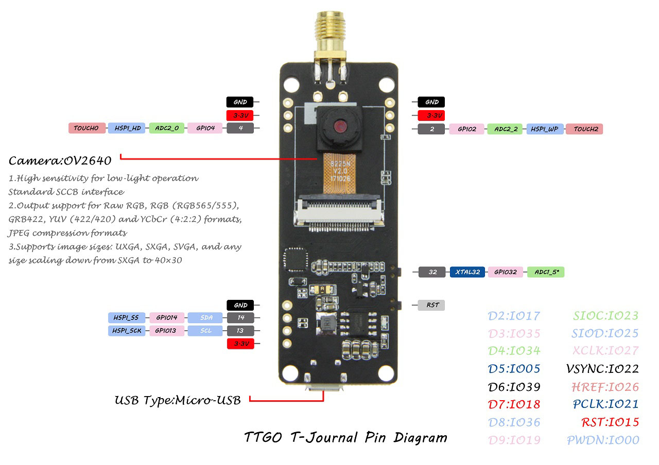
 Here's a table with the connections between the ESP32 and the camera:
 This board comes with an I2C SSD1306 0.91 inch OLED display. To interact with the display you can use the Adafruit SSD1306, the oled-ssd1306 or other compatible libraries. We usually use the Adafruit SSD1306 along with the Adafruit_GFX to interact with OLED displays.
The OLED communicates with the ESP32 using the following pins:
This board comes with an I2C SSD1306 0.91 inch OLED display. To interact with the display you can use the Adafruit SSD1306, the oled-ssd1306 or other compatible libraries. We usually use the Adafruit SSD1306 along with the Adafruit_GFX to interact with OLED displays.
The OLED communicates with the ESP32 using the following pins:

 Learn more about this project: ESP32-CAM Video Streaming Web Server
 Learn more about this project: ESP32-CAM Take Photo and Display in Web Server
 Copy the following to the camera_pins.h file.
 Then, simply click the Arduino IDE upload button and it is done!
 For demonstration purposes, we'll send BME280 sensor readings from one board to the other. The receiver will display the readings on an OLED display.
If you have an ESP8266 board, you can read this dedicated guide: ESP8266 NodeMCU Client-Server Wi-Fi Communication.
For demonstration purposes, we'll send BME280 sensor readings from one board to the other. The receiver will display the readings on an OLED display.
If you have an ESP8266 board, you can read this dedicated guide: ESP8266 NodeMCU Client-Server Wi-Fi Communication.
 The ESP32 server creates its own wireless network (ESP32 Soft-Access Point). So, other Wi-Fi devices can connect to that network (
 For this tutorial, you need the following parts:
2x ESP32 Development boards read Best ESP32 Boards Review
BME280 sensor
I2C SSD1306 OLED display
Jumper Wires
Breaboard
You can use the preceding links or go directly to MakerAdvisor.com/tools to find all the parts for your projects at the best price!
For this tutorial, you need the following parts:
2x ESP32 Development boards read Best ESP32 Boards Review
BME280 sensor
I2C SSD1306 OLED display
Jumper Wires
Breaboard
You can use the preceding links or go directly to MakerAdvisor.com/tools to find all the parts for your projects at the best price!
 The ESP32 server is an Access Point (AP), that listens for requests on the /temperature, /humidity and /pressure URLs. When it gets requests on those URLs, it sends the latest BME280 sensor readings.
For demonstration purposes, we're using a BME280 sensor, but you can use any other sensor by modifying a few lines of code.
The ESP32 server is an Access Point (AP), that listens for requests on the /temperature, /humidity and /pressure URLs. When it gets requests on those URLs, it sends the latest BME280 sensor readings.
For demonstration purposes, we're using a BME280 sensor, but you can use any other sensor by modifying a few lines of code.
 This means that the access point was set successfully.
Now, to make sure it is listening for temperature, humidity and pressure requests, you need to connect to its network.
In your smartphone, go to the Wi-Fi settings and connect to the
This means that the access point was set successfully.
Now, to make sure it is listening for temperature, humidity and pressure requests, you need to connect to its network.
In your smartphone, go to the Wi-Fi settings and connect to the  While connected to the access point, open your browser and type 192.168.4.1/temperature
You should get the temperature value in your browser:
While connected to the access point, open your browser and type 192.168.4.1/temperature
You should get the temperature value in your browser:
 Try this URL path for the humidity 192.168.4.1/humidity:
 Finally, go to 192.168.4.1/pressure URL:
 If you're getting valid readings, it means that everything is working properly. Now, you need to prepare the other ESP32 board (client) to make those requests for you and display them on the OLED display.
 The ESP32 Client is a Wi-Fi station that is connected to the ESP32 Server. The client requests the temperature, humidity and pressure from the server by making HTTP GET requests on the /temperature, /humidity, and /pressure URL routes. Then, it displays the readings on an OLED display.

 The sensor readings are also displayed in the OLED.
 That's it! Your two boards are talking with each other.

 We'll take a look at how a relay module works, how to connect the relay to the ESP32 or ESP8266 boards and build a web server to control a relay remotely.
 There are relay modules whose electromagnet can be powered by 5V and with 3.3V. Both can be used with the ESP32 or ESP8266 you can either use the VIN pin (that provides 5V) or the 3.3V pin.
Additionally, some come with built-in optocoupler that add an extra layer of protection, optically isolating the ESP boards from the relay circuit.
There are relay modules whose electromagnet can be powered by 5V and with 3.3V. Both can be used with the ESP32 or ESP8266 you can either use the VIN pin (that provides 5V) or the 3.3V pin.
Additionally, some come with built-in optocoupler that add an extra layer of protection, optically isolating the ESP boards from the relay circuit.
 On the left side, there are two sets of three sockets to connect high voltages, and the pins on the right side (low-voltage) connect to the ESP GPIOs.
 The relay module shown in the previous photo has two connectors, each with three sockets: common (COM), Normally Closed (NC), and Normally Open (NO).
 The low-voltage side has a set of four pins and a set of three pins. The first set consists of VCC and GND to power up the module, and input 1 (IN1) and input 2 (IN2) to control the bottom and top relays, respectively.
If your relay module only has one channel, you'll have just one IN pin. If you have four channels, you'll have four IN pins, and so on.
The signal you send to the IN pins, determines whether the relay is active or not. The relay is triggered when the input goes below about 2V. This means that you'll have the following scenarios:
The low-voltage side has a set of four pins and a set of three pins. The first set consists of VCC and GND to power up the module, and input 1 (IN1) and input 2 (IN2) to control the bottom and top relays, respectively.
If your relay module only has one channel, you'll have just one IN pin. If you have four channels, you'll have four IN pins, and so on.
The signal you send to the IN pins, determines whether the relay is active or not. The relay is triggered when the input goes below about 2V. This means that you'll have the following scenarios:
 The second set of pins consists of GND, VCC, and JD-VCC pins. The JD-VCC pin powers the electromagnet of the relay. Notice that the module has a jumper cap connecting the VCC and JD-VCC pins; the one shown here is yellow, but yours may be a different color.
With the jumper cap on, the VCC and JD-VCC pins are connected. That means the relay electromagnet is directly powered from the ESP power pin, so the relay module and the ESP circuits are not physically isolated from each other.
Without the jumper cap, you need to provide an independent power source to power up the relay's electromagnet through the JD-VCC pin. That configuration physically isolates the relays from the ESP with the module's built-in optocoupler, which prevents damage to the ESP in case of electrical spikes.
The second set of pins consists of GND, VCC, and JD-VCC pins. The JD-VCC pin powers the electromagnet of the relay. Notice that the module has a jumper cap connecting the VCC and JD-VCC pins; the one shown here is yellow, but yours may be a different color.
With the jumper cap on, the VCC and JD-VCC pins are connected. That means the relay electromagnet is directly powered from the ESP power pin, so the relay module and the ESP circuits are not physically isolated from each other.
Without the jumper cap, you need to provide an independent power source to power up the relay's electromagnet through the JD-VCC pin. That configuration physically isolates the relays from the ESP with the module's built-in optocoupler, which prevents damage to the ESP in case of electrical spikes.
 In this example, we're controlling a lamp. We just want to light up the lamp occasionally, so it is better to use a normally open configuration.
We're connecting the IN1 pin to GPIO 26, you can use any other suitable GPIO. See ESP32 GPIO Reference Guide.
In this example, we're controlling a lamp. We just want to light up the lamp occasionally, so it is better to use a normally open configuration.
We're connecting the IN1 pin to GPIO 26, you can use any other suitable GPIO. See ESP32 GPIO Reference Guide.
 We're connecting the IN1 pin to GPIO 5, you can use any other suitable GPIO. See ESP8266 GPIO Reference Guide.
The best ESP8266 pins to use with relays are: GPIO 5, GPIO 4, GPIO 14, GPIO 12 and GPIO 13.
We're connecting the IN1 pin to GPIO 5, you can use any other suitable GPIO. See ESP8266 GPIO Reference Guide.
The best ESP8266 pins to use with relays are: GPIO 5, GPIO 4, GPIO 14, GPIO 12 and GPIO 13.
 Copy the following code to the main.py file and upload it to your board. It lights up your lamp for 10 seconds and turn it off for another 10 seconds.
 In this section, we've created a web server example that allows you to control a relay remotely via web server.
 Then, open a browser in your local network and type the ESP IP address to get access to the web server.
You should get a web page with a toggle button that allows you to control your relay remotely using your smartphone or your computer.
Then, open a browser in your local network and type the ESP IP address to get access to the web server.
You should get a web page with a toggle button that allows you to control your relay remotely using your smartphone or your computer.


 Learn how to control a relay module with ESP8266 board:
  In this section, we've created a web server example that allows you to control as many relays as you want via web server whether they are configured as normally opened or as normally closed. You just need to change a few lines of code to define the number of relays you want to control and the pin assignment.
To build this web server, we use the ESPAsyncWebServer library.
In this section, we've created a web server example that allows you to control as many relays as you want via web server whether they are configured as normally opened or as normally closed. You just need to change a few lines of code to define the number of relays you want to control and the pin assignment.
To build this web server, we use the ESPAsyncWebServer library.

 Now, you can use the buttons to control your relays remotely using your smartphone.